 |
|
|
|
|
|
|
|
|
|
|
|
|
|
|
|
|
|
|
|
|
|
|
|
|
|
|
|
|
|
|
|
|
|
|
|
|
|
|
|
|
|
|
|
|
|
|
|
|
|
|
|
|
|
|
|
|
|
|
|
|
|
|
|
|
|
|
|
|
|
|
|
|
|
|
|
|
|
|
|
|
|
|
|
|
|
|
|
|
|
|
|
|
|
|
|
|
More on the Early L.5 Summary of L.5 Year Features
In the years leading up to World War two, and the production of what was to become the well-known L.5 lathe, the Harrison range consisted of: the Model J.L.1 5-inch "Jubilee" woodworking: the Model L.1.A "Union" light-pattern plain-turning lathe - this being made with a permanent gap bed and in centre heights of 3.5, 5 and 6 inches and driven by treadle, countershaft or directly from a motor held inside the headstock-end leg: also available were a pair of similar but better-specified models, the "Union" 3.5-inch L.1.A.S. and 5-inch L.2.A.S. with backgear and screwcutting - and again with a choice of drive systems to suit the purchaser's circumstances: more industrial and heavier in appearance was the "Improved" L.2-6, available as a either a 4.5-inch or 5.5-inch model and with either flat-belt drive or a geared headstock - this was the lathe that would, during the war, become the basis of the L.5 range and develop into the most popular and widely-sold of the company's models; the largest machine to be offered was the L.21 "Toolroom" equipped with a screwcutting gearbox and sold with flat belt drive as the L.21 or, in geared-headstock form, as the L.21.A.
The L.5, the subject of this article, has a deceptive appearance for, although its weight and bulk were nearly as great as a Colchester student (and it was a very strong machine) its centre height was only 4.5" (114 mm); the L.5A had its capacity increased to 5.5 inches (but was otherwise largely unchanged) whilst the "11-inch" and "140" models were late production variants with a specification that had been steadily improved to help cope with heavier work and higher speeds. Both standard and long-bed versions of all models were made, offering either 24" or 40" (508/1016 mm) between centres.
The L.5 was never given "Mark" numbers to distinguish the numerous minor changes made to it over the years; however, a summary of these differences, and an approximate guide to the year of their appearance is:
Flat-belt & Geared Head Drive: late 1930s to about 1946 with a light bed foot under the headstock and a spoked handwheel on the carriage traverse. This was not an L.5 but its immediate forebear the previously-mentioned L2-6.
Mk. 1 Geared Headstock - late 1930s (as the "Improved" L.2-6) and developed until around 1945: 3/4" bore spindle running in plain bearings; a lift-off headstock cover with the letters "A" and "B" cast into the front face; micrometer markings engraved into the flat rims of the cross and top slide handwheels; cast-iron plinth under the headstock and a simple leg under the tailstock end of the bed (although some full cabinet stands in cast iron were also manufactured); flat-sided, triangular form, cast-aluminium bolt-on changewheel cover; a clutch operated by a bed-length horizontal bar and the power feeds engaged by a lever with a bronze trigger.
Mk. 2 - 1946 to 1949: full-length cabinet stand fabricated from heavy-gauge sheet steel; roller-bearing headstock with a smaller, bolt-on top cover with a raised rib around its lower front edge and a small spindle-speed plate in the centre; conventional zeroing micrometer dials; large bolt-on changewheel and belt cover cast in one piece with two curved faces to the front; short clutch operating lever pivoting on just the headstock.
Mk. 3 - 1950 to 1956: headstock spindle with the option of either 0.75" or 1.25" clearance through the bore (the latter very rare indeed); a headstock cover without the "A" and "B" letters but with a larger spindle-speed chart often protected by a transparent plastic plate; large cast-aluminium combined changewheel and belt-guard with hinge-open gear cover; tailstock barrel clamp positioned vertically at the rear rather than horizontally over the top of the smoothed-off casting; exposed spring and bronze thumb catch removed from the apron-mounted power-feed engagement lever and its material changed to a metal rod; leadscrew reverse control knob changed from solid steel with a knurled edge to plastic with seven finger grips; 3-speed feeds and screwcutting gearbox with downward-pointing cast-iron lever changed to an enclosed type with an upwards-pointing rod lever; Harrison nameplate attached to a headstock-mounted plate as well as appearing on the bed - and sometimes the stand as well.
Continued below:
|
|
|
|
|
|
|
|
 |
|
|
|
|
|
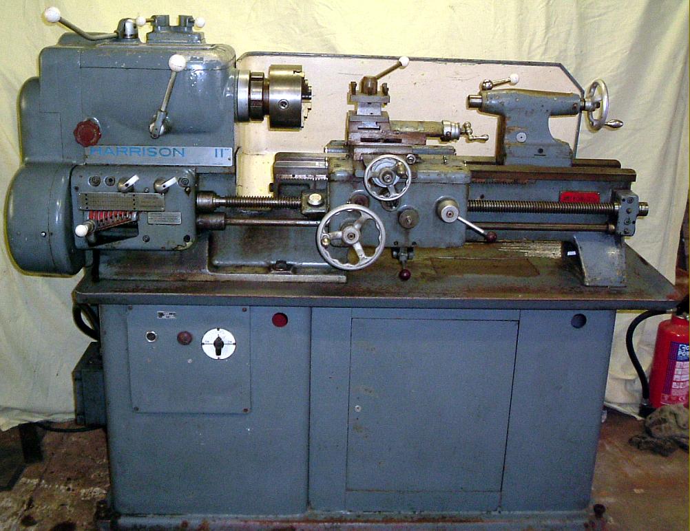
Typical late-model Harrison badged as an "11-inch" and fitted with a full (Inch) screwcutting & feeds gearbox
|
|
|
|
|
|
|
|
|
|
|
|
|
|
|
Continued:
Mk. 4 - 1957 to 1966: cross-feed and carriage traverse handwheels with 3 spokes and internal finger grips; large speed-change lever on front face of headstock fitted with safety catch requiring the lever to be pulled out before it could be moved sideways. Although the L.5 continued to be advertised during the early 1960s the 5.5-inch centre height L.5A was already in production by 1958.
Originally fitted with a removable gap piece as standard by the 1950s, as straight-bed hydraulic-copying lathes were introduced, the gap on the ordinary lathe became an extra-cost option. The gap made a substantial difference to the capacity of the lathe, for, even on the 4.5" centre-height model, it allowed work up to 4.25" (114 mm) thick and 17" (432 mm) in diameter to be turned - and up to 18.75" (476 mm) on the 11-inch swing L.5A. The beds of early lathes were not hardened and, even through this process was offered as an extra, it is rare to find one so specified. Later models, from an indeterminate date some time in the mid 1950s had hardened beds as standard. Very occasionally an example of the L.5, from the mid 1940s onwards is found mounted on a full-length cast-iron cabinet stand - as are (surprisingly) very limited numbers of later models. However, no mention is made of this stand - nor are any pictures evident - in any of the many catalogues seen by the writer. Although early lathes are generally found supported at the headstock end on a cast-iron plinth with a simple leg at the tailstock end, by far the most common Harrison stand is one fabricated from heavy-section steel plate with a locking storage cupboard and deep chip tray.
Headstock
The headstock of the L.5 was always fitted from the start of production with a combined clutch and brake unit, a fact that makes amateur operation by a single-phase motor very much easier. Unfortunately, although a reliable unit, the clutch on all models is prone to rattle, a situation nearly always exacerbated by the use of a single-phase motor or a phase converter. The first L.5 models of the 1940s had a headstock spindle running in plain bronze bearings but all later versions, from the late 1940s, were fitted with pre-loaded, opposed Timken taper roller bearings at the front of the headstock spindle and a single-row ball bearing at the rear; the main double gear that slid along the spindle was cut from a single forging and slid on six (later seven) splines - the complete assembly being dynamically balanced. On early machines the headstock gears were in cast iron but on later models, from an unspecified date, an improved specification was introduced with all the gears hobbed from the solid, shaved, induction hardened and honed to produce the correct tooth form. The first lathes had a spindle nose with a 1.5-inch, 6 t.p.i. thread and a bore of just 0.75" but in the early 1950s the option was offered (at extra cost) of a 2.25-inch x 6 t.p.i. nose with a must more useful 1.25" bore. When the increased centre height L.5A was introduced its spindle (with a slightly larger 1.375" (35 mm) hole was also offered on the smaller machine - though this is rarely found.
Offered first on the export market, the L.5A was, at first, just an L.5 with an increased centre height so that it could be sold, in American parlance, as an "11-inch" machine. Besides the two sizes of spindle thread/bore, one very belated extra (later to become standard) was the option of the much safer and more rigid American L00 (L-zero-zero) nose. The L.5.A eventually became the "140" and was fitted with a distinctive "square-front" headstock - and had the large-bore spindle and L00 nose fitting as standard.
On all models 8 spindle speeds were normally available (16 on lathes with 2-speed motors) with the range most commonly found on second-hand L.5/L.5A/140 machines being 31 to 720 r.p.m. However, various other options were available over the years including:
21 to 480 rpm - 1000 rpm 3-phase motor with an input speed to the headstock of 500 r.p.m. - common on early machines and also used on later ones in conjunction with a low-power motor for safety in training establishments
31 to 720 rpm - 1.5 hp 1500 rpm motor
42 to 960 rpm - 2 hp 1500 rpm motor
62 to 1440 rpm - alternative range with the 2 hp 1500 rpm motor
31 to 1400 rpm - 16 speeds: two-speed 1.5/3 hp 1500/3000 rpm motor
62 to 1400 rpm - 16 speeds: alternative range with two-speed 1.5/3 hp 1500/3000 rpm motor
22 to 500 rpm - 1 hp motor
34 to 750 rpm - 1.5 hp motor
45 to 1000 rpm - 16 speeds: 2-speed 1.5/3 hp 1500/3000 rpm motor
34 to 1500 rpm - 16 speeds: alternative range with 2-speed 1.5/3 hp 1.5/3 hp 1500/3000 rpm motor
A few lathes were also made with a special "high-speed" headstock that gave 45 to 2000 rpm from a 2-speed motor. The clutch on higher-speed model (and the 140) was supported on two ball races - instead of the single roller bearing employed on the single-speed motor versions. However, there appears to have been no difference in either the size or quality of the headstock gears and only one bush, on the layshaft, was shown in the Parts List as being different. There appears to be no reason, therefore, why the top speed of the slower models cannot be safely increased to around 1500 rpm to make them very much more useful (see below).
Screw-thread Spindle fittings L.5, L.5A
The small-bore spindle was threaded 1.5" x 6 t.p.i and the large bore spindle 2.25" x 6 t.p.i. The option of a screwed spindle nose was withdrawn on the 31st. of December, 1959.
Selecting Spindle Speeds
Because the control levers were "interlocked", to prevent the engagement of two gears at once (and work in a rather unusual way), it is not always clear to a beginner how the spindle speed should be changed; here is the method of operation:
each of the two selector on top of the headstock can be placed in one of three positions
to select a new speed, either of the two levers must first be placed in its central, or "neutral", position
the other lever can then be turned to either its full-left, or full-right position
by juggling these positions (one lever in neutral, one engaged) new speeds are selected.
However, don't expect the speed-indicator diagram to help you determine which setting you have selected - it's a masterpiece of convoluted lines and what appear to be randomly placed numbers and certainly not something that can be taken in at a glance. Before either selector lever can be moved it is often necessary, as on any gearbox with straight-cut teeth, to ease the spindle round a little to permit the gears to engage. A third, much larger lever, pointing upwards and located on the headstock front cover was used to select the high and low-speed ranges. On early models this lever had no protection against accidental movement but later a spring-loaded safety lock was incorporated that meant the lever had to be pulled out before its position could be altered.
Harrison headstocks are not noted for quiet running - although some machines do seem better in this respect than others - and is usually blamed on a combination of "ringing" from the hardened headstock gears and clatter from the steel changewheels. Providing there are no deep rumblings, or obvious vibrations, noise from the headstock has to be considered as just an annoying inconvenience. A story that emerged from the works during WW2 (and almost certainly not apocryphal) was that Russian inspectors, fearful of sending back machines to the Stalinist dictatorship that were in any way imperfect, complained that a batch of lathes was far too noisy. An apprentice was found and the machines demonstrated to him by a foreman. He was told him that one solution was to fill the headstocks a mixture of oil and a little light lapping paste and run them until they quietened down. The units could then stripped, thoroughly cleaned and new bearings fitted. However, as non of the works staff dared do this he, as an apprentice, was certainly not to try it - whereupon the foreman handed over a large can of lapping compound together with several tins of oil - and departed.
None of the speed-change levers on the headstock should be moved until the spindle has completely stopped. The original high/low spindle-speed selector on the front face of the headstock could be moved freely from position to position and so had no protection against being accidentally moved when the machine was running. On Mk. 4 models, from approximately 1959, the option was offered of a spring-loaded safety "guard" that required the handle to be pulled outwards before it could be moved; this fitting was eventually provided as standard.
Continued below:
|
|
|
|
|
|
|
|
|
|
|
|
|
|
 |
|
|
|
|
|
|
Continued:
Screwcutting & Power Feeds
The L.5 and L.5A were supplied as standard with a three-speed "translation box" that, unlike the equivalent Colchester model, offered the luxury of three (instead of two) lever-selected sliding and surfacing speeds for each setting of the changewheels; the very early 3-speed gearboxes had their cast handwheel pointing downwards, but later machines it was arranged to point upwards. The standard set of changewheels supplied with the 9-inch lathe (20, 40, 50, 55, 60 x 2, 65, 70, 80 and 100) provided 26 threads from 2.5 to 40 t.p.i (with the option of a 120t wheel to give an additional seven threads up to 80 t.p.i) whilst those with the standard 11-inch lathe enabled 33 threads from 2.5 to 80 t.p.i to be generated.
An optional-extra on the L.5A ,11-inch and 140 models (but almost certainly a standard fitment on the 140 and L.6) the standard screwcutting gearbox gave a choice of 36 threads and feeds from 4 to 60 t.p.i., while a set of conversion gears (at extra cost) enabled the box to generate 15 metric pitches from 0.5 mm to 7 mm.
An all-metric box was also listed, easily identified by a row of three aluminium "thumb" levers arranged in a line across the top edge (the "inch" (imperial) box had just two). The gears inside the metric box were identical to those in the "inch" version and the two (left hand) thumb arranged the same 2:1 ratio stages. The third (right hand) thumb lever did not (as on many other makers' boxes) engage the leadscrew or fine feed drive, but instead switched between a pair of 21t/21t and 21t/20t gears to give an increase in pitch of exactly 1.05:1. Harrison clearly, in saving money by using the imperial internals, had made this modification in order to obtain a reasonable number of metric pitches. In addition. there might have been a 2:1 speed increase in this third stage as the input changewheels reduce the input speed by that ratio (and the table of imperial threads printed in the manual is actually the reverse - a mirror image - of that obtained from the tumbler lever (that's the one fitting into a line of 9 holes). Unusually compact (engineering speak for too small) the gearbox suffered from the lack of a lubrication sump, oil having to be squirted in by the operator - when he remembered. Whilst the rest of the lathe was heavily built if a fault is to be found in a well-used example it will almost certainly be within the gearbox - and so a careful inspection of this component, and a run through all the lever positions under power, is strongly advised.
Power feeds available with the 3-speed gearbox model ranged from 0.002" to 0.50" sliding and 0.001 to 0.030" surfacing; the screwcutting gearbox model offered 0.002" to 0.065" sliding and 0.001" to 0.37" surfacing. However, on very early models, instead of being set at 50% of the sliding rate the power cross fed was designed to run at a too-fast 75%. The leadscrew was only used for screwcutting and engaged by a simple, hand-operated, sliding dog-clutch at the gearbox end of the shaft; the power shaft, below the leadscrew, was provided with a spring-loaded, safety over-ride mechanism to prevent damage in the case of a dig-in, mechanical mayhem or operator incompetence. Later lathes were offered as "all-metric" machines with a proper metric screwcutting gearbox; these improved lathes, in both metric and English-screwcutting form, can be recognised (even if the plates are missing) by a third thumb lever to the right of the usual two in a line along the top of the box. Both shafts were now protected by spring-loaded over-run clutches, an essential feature on machines intended for training workshops. Apart from the earliest L.5 models, on Harrison lathes of all types prior to the M Series the changewheels were guarded by well made, hinge-open, cast-aluminium cover - whereas the equivalent Colchester models had covers that, whilst also in cast aluminium, had to be pulled off their long mounting studs and (before they could be replaced) the loose, knurled-edge round retaining nuts hunted down to where they had rolled when the operator dropped them. The changewheels were made from steel, not cast iron and, as a result, can set up quite a ringing noise at higher spindle speeds; careful adjustment of backlash between mating teeth together with the use of a heavier, "open-gear" lubricant can help minimise this problem.
Carriage
Although all models of the L.5 and its variants had a doubled-walled apron, non were equipped to hold a reservoir of lubricant within its base; all used a push/pull button to select either power sliding or surfacing whilst the feeds engagement lever, below the centre of the apron, was spring loaded and could be snapped in and out even under full load; the design was so simple, effective and easy to use that it was adopted across the entire Harrison range. Early L.5 aprons were slightly different, the spring-loaded engagement lever having a bronze trigger instead of the later prosaic rod topped by a plastic knob. A thread-dial indicator was fitted as part of the standard equipment.
Continued below:
|
|
|
|
|
|
|
|
 |
|
|
|
|
|
|
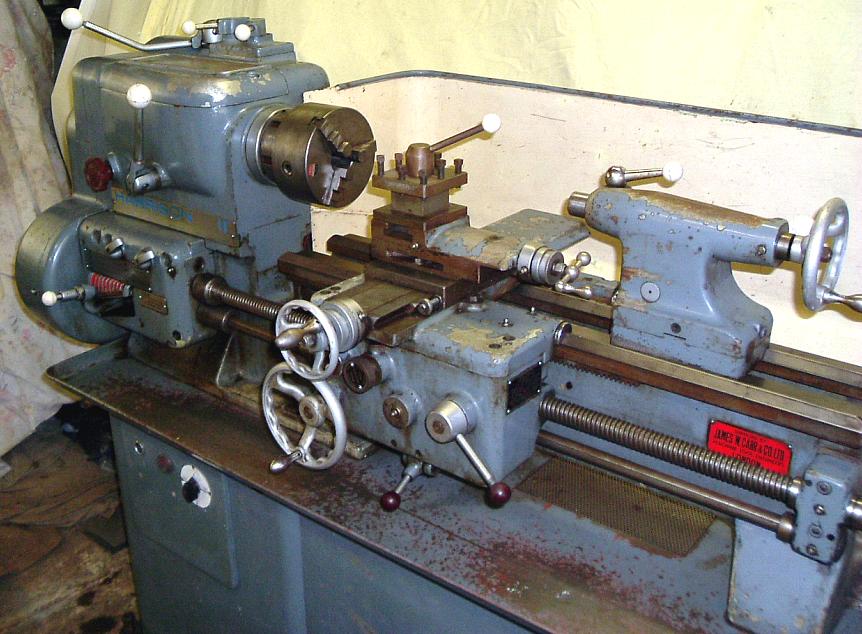
Harrison L5/L5A/11-inch with 3-speed screwcutting and feeds gearbox
|
|
|
|
|
|
|
|
|
|
|
|
|
|
|
|
|
Continued:
Compound Slide Rest
On all models the top slide could be turned through 360 degrees and the cross slide was fitted with a proper taper gib strip - instead of the flat strip with push-screw adjustment often found on smaller industrial lathes machines of this age. The very first models had enormous (non-zeroing) micrometer dials, cheaply and effectively achieved by engraving the division marks into the flat rim of both cross and top-slide handwheels. Stalks extending from the end brackets of each slide reached up to the inner edge of each handwheel to provide a flat surface into which a zero mark was engraved. Later machines, probably concurrent with the change to a shallower headstock top cover were fitted with conventional zeroing micrometer dials, which, whilst not big enough, were nonetheless of adequate dimensions for younger eyes. A "clog-heel" toolpost was fitted as standard but both 4-way toolpost, and later a quickset toolholder, were on the options' list; the 4-way toolpost had a clamping bar with a small white plastic ball on its end - it's surprising just how many of these palm-hurting devices have survived unmodified when, for a few pence extra, something more comfortable could have been fitted. Unfortunately the cross slide was not, as on the later M Type lathes, of the full-length type; instead, a short unit was used that, over time, tended to wear just the middle section of the (saddle) ways. Sheet-metal guards (frequently damaged or missing on used machines) were set above the cross-feed screw at the front and rear to protect it from the damaging effects of swarf; later models retained the tin front cover but were given a more elegant and robust cast-aluminium guard at the rear. Because the centre height of the original L.5 was only 4.5-inches - and the saddle and cross slide very heavily built - there was insufficient depth in the top slide to machine a T-slot. Consequently the toolpost, single or 4-way, was secured by a stud. When the 5.5-inch centre height L.5A was introduced the saddle and cross-slide castings remained unchanged but the thickness of the top slide was increased sufficiently to bring the tool deck up to the right height and allow a T slot be included - a modification that allowed alternative toolposts and other fittings to mounted with far greater ease.
Harrison 11-inch and 140
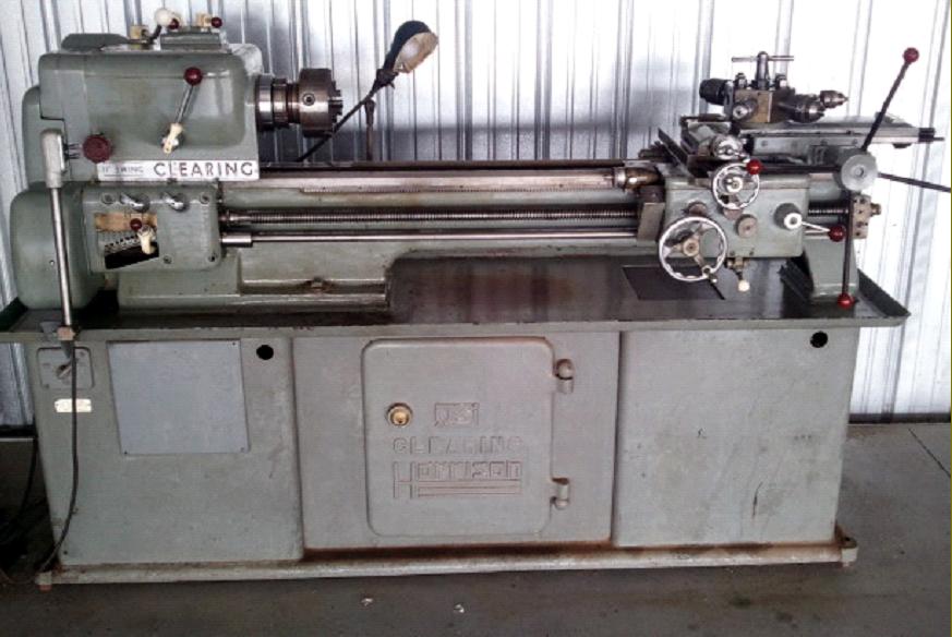
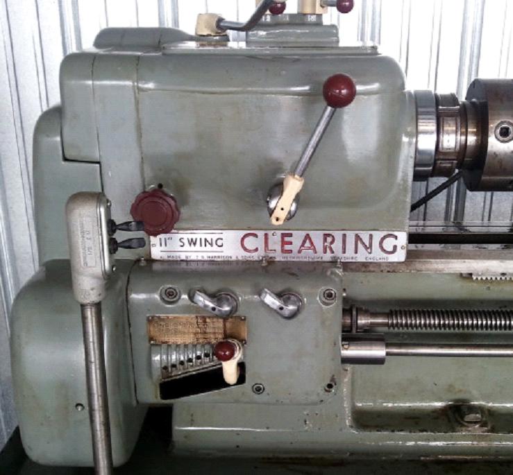
Lathes badged as "Harrison 11-inch" or "140" on a steel strip along the front of the headstock are, in effect, just the last of the L.5A type; they have a 5.5" centre height but, instead of a screwed thread on the spindle nose, were supplied as standard with the much safer and more rigid American L00 ("L-zero-zero") fitting. These models are also found badged using the Kerry name - though why the management of the 600 Group (who eventually owned both Kerry and Harrison) would want to cause confusion between the Harrison and quite different and long-established Kerry lathe of the same capacity is unclear. In the USA and Canada the lathe was also distributed as the "Clearing". Although the headstock of the 140 was made squarer in appearance from an examination of the parts list and machines in service it seems to have contained (with the exception of some minor differences in the selector mechanism) the same internals. One distinct difference was the clutch which employed the same twin ball-race unit as fitted to the rare 2000 rpm L.5A and 11-inch models. Stands and drive systems also varied with some machines having an externally-mounted motors and other (including all those supplied with hydraulic copying equipment) with internal motors fastened to a large, vertical hinged plate.
Stands:
An ex-Harrison employee told me that great care was taken to assemble and shim the lathes onto their stands - and that it would be a Very Bad Idea Indeed to disturb this cosy relationship. Harrison also recommended that the stands, being rigid units, were not bolted down, but set on steel plates, on a concrete floor, with jacking screws fitted into the holes at each corner and the lathe set to allow coolant to drain to one end. Although the cast-iron stands are very heavy and difficult to move, they also provide the best foundation for the lathe - and must have been very expensive to produce.
Conversion to Single-phase Electrics and Higher Top Speeds
The electric motor on the L.5 and L.5A was mounted externally, low down on the back of the stand, and fitted to a pair of vertically-slotted, adjustable motor rails; this feature makes motor replacement a relatively easy job, the rails being bolted to a wide, flat surface and hence, with drill and thread tap to hand, easily relocated. Some later machines were fitted with motor rails that could be adjusted along horizontal slots as well vertically - and a change of motor on these could hardly be simpler. I know of several older Harrison lathes where the owners have fitted more powerful motors, together with a larger drive pulley to increase the top speed to a more useful 1500 rpm or so; no problems have been encountered - and lathes appear to run perfectly. On the "Works" high-speed 2000 rpm lathes a special clutch was fitted that employed a ball race at each side of the 3-step V pulley instead of a single roller race on the inside only; if contemplating speeds in this region it might be wise to give consideration to the careful handling of the clutch control so as not to overload it.
The larger models had the motor contained within the cabinet stand - usually on a large rectangular dished plate hinged along its lower edge and pivoted on two bosses welded low down on the back of the stand; the plate was arranged to swing backwards and could be lowered to the floor behind the lathe so completely exposing the motor. Inside the plate was a pair of motor rails, arranged at ninety degrees, that allowed not only easy adjustment of the belt tension but also - because the motor could be shuffled around on the rails until it lined up with the headstock pulley - enabled it to be easily changed for one of a different size or make.
A partial list of Serial Numbers can be found here and an illustrated summary of the L.5's continuous development here..
|
|
|
|
|
|
|
|
 |
|
|
|
|
|
|
|
|
|
L5A/11-inch compound slide rest, 4-way toolpost on a T-slot top-slide, bed-mounted multi-stop and dial-thread indicator.
|
|
|
|
|
|
|
|
|
|
|
|
|
|
|
|
 |
|
|
|
|
|
|
The changewheels were made from steel, not cast iron, and as a result could set up quite a ringing noise at higher spindle speeds; careful adjustment of backlash between mating teeth, and the use of a heavier, "open-gear" lubricant helpes to minimise this problem.
|
|
|
|
|
|
|
|
|
|
|
 |
|
|
|
|
|
|
L5A/11-inch carriage with the thicker top slide casting that allowed the use of a T-slot to retain the toolpost. This machine has the large bore, threaded headstock spindle.
|
|
|
|
|
|
|
|
|
|
|
|
|
|
|
|
|
|
 |
|
|
|
|
|
|
North American market L5A/11-inch badged as a "Clearing"
|
|
|
|
|
|
|
|
 |
|
|
|
|
|
 |
|
|
|
|
|
|
When the increased centre height L.5A was introduced its spindle (with a slightly larger 1.375" (35 mm) hole was also offered on the smaller machine L5 - though this is rarely found.
|
|
|
|
|
|
|
|
|
|
|
|
|
|
|