|
Home Machine Tool Archive Machine-tools Sale & Wanted Harrison Home Page L5 Early Model Later L5 9" & L5A 11-inch" 140 L5 Accessories 10-inch Late 10" & 12" L6 Early 12" L6 Late L6 Mk. 3 13" & 15" Late Models 13" 14" 16" 17" Hydraulic Copy Lathes Harrison Union Lathes Models 155 and 165 Model 190 14", 16" & 17" Accessories |
|
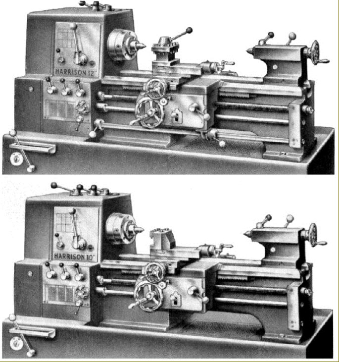
Built in tiny numbers from around 1966 to 1968 these 10-inch and 12-inch lathes were of an almost completely different design to the original L Models, had smooth-faced stands unlike any used by Harrison before and with features that foreshadowed the modern M Series lathes of the 1970s. The 12-inch was the second such size to be made by Harrison - and hence the MK. 2 - but was replaced after only 2 years by the Mk. 3 that used a similar configuration of headstock but a new type of screwcutting and feeds gearbox but with the apron design as used on older L5/L5a/11-inch models. The 10-inch appears to have been discontinued on the introduction of the Mk.3 12-inch. In turn this lathes were superseded by new and rather longer-lived 13 and 15-inch models. |
|
|
||