|
|
|
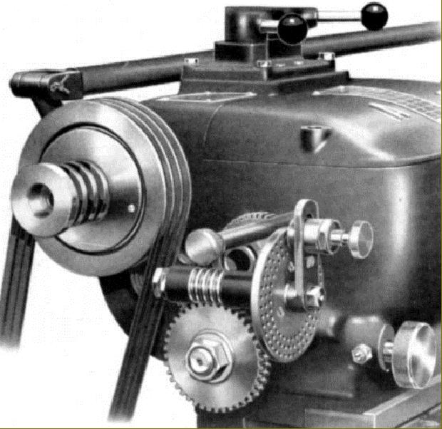
Spindle-mounted dividing assembly - a very rare accessory offered only until the late 1950s. Note the tripe V-belt drive and the very early design of clutch control, made in the form of a rod that extended the full length of the bed and allowed the operator to reach it from any working position. |
||

|
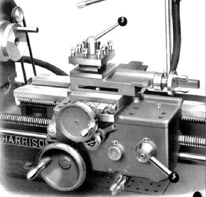
Another style of dividing accessory available even before WW2. An equally rare type but this time carried by a top-slide mounted single-swivel vertical slide. Because the vertical slide was mounted on the top slide its mounting boss was hollowed out to provide clearance for the (optional) 4-way toolpost indexing pawl. |
||
|
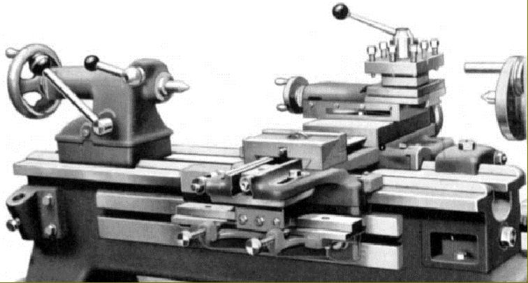
Taper-turning unit. The cross-slide screw (at least on later models) was telescopic, which eliminated the need to remove the cross-feed nut when using the unit. A taper length of up to 11" could be turned at one setting. |
||
|
6-station Bed Turret. Used for repetition or quantity production work the unit fitted the lathe bed and could be operated even with the standard carriage still in place. On the longer-bed models it was possible to move the standard carriage to the tailstock end of the bed and fit a separate cut-off slide (not illustrated) so further improving the machine's work capacity. |
||
|
15-inch diameter faceplate for use with the gap piece removed. The maximum swing in the gap is 17" on the 9-inch swing lathe and 18.75" on the 11-inch swing lathe. |
||
|
Toolpost grinding Attachment. The unit was complete with a 0.25 hp motor which generated a single spindle speed of 30,000 rpm. The reach of the shaft for internal grinding was 4.5 inches and the device came complete with five internal grinding wheels of 3/8", 1/2", 5/8", 3/4" and 1" diameter. A 6" x 1/2" external grinding wheel was also included, together with a pulley to reduce the spindle speed to a safe 3,600 rpm when it was being used. |
||
|
|
||
|
Draw-tube type Collet Attachment operated by a handwheel. The 3/4" bore spindle accepted collets up to a maximum capacity of 0.5" whilst machines with the 1.25" bore spindle could accept double that. |
||
|
Lever-action Collet Attachment.. The 3/4" bore spindle accepted collets up to a maximum capacity of 0.5" whilst machines with the 1.25" bore spindle could accept double that. |
||
|
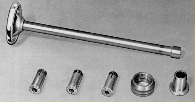
Collet set with drawbar, spindle nose insert adapter and spindle-thread protection cap. Made by Crawford the standard collet set was from 1/16" to 1" in steps of 1/16". However collets at intervals down to 1/64th inch were available (though very rarely found) as well as metric. Through capacity was limited by the size of the spindle adapter and the set was specifically intended for smaller work. Larger collets could be had in the form of the Burnerd adjustable "Multi-Size" type that involved the use of a screw-on collet holder operated by lever or key. |

|
|
||