email: tony@lathes.co.uk
Home   Machine Tool Archive   Machine-tools Sale & Wanted
Machine Tool Manuals   Catalogues   Belts   Books  Accessories

HARRISON M450 Lathe

An Operation, Maintenance & Parts Manual is available for the M450

M250   M300   M350 & 390  M400   M450   M500   M300 Photo Essay
   
VS330 (Export Model "AA")  Older Harrison Models 

Harrison 10AA (Chipmaster)


Developed directly from the M400, the M450 was fitted out for more arduous work and designed to ISO standards R1708, DIN 8608 and BS4656 as a general-purpose machine suitable for both production use and in maintenance and repair shops - and, optionally, as a toolroom lathe to BS4656, DIN 8605 and ANSI-B5-16. The practical outcome of the various tests meant that a length of free cutting mild steel 250 mm long and approximately 56 mm in diameter was guaranteed to turn within 0.01 mm - though tests on a large batch of machines showed that this figure was always bettered and had an average value of 0.0025 mm 
Although of the same capacity, early machines were rather different to the later ones, having a different design of apron (the first had a flat face, later ones being typical of the larger M-Series lathes in having a raised section in the centre) and a more restricted threading range. They were also badged differently for the American and Canadian markets carrying headstock-mounted badges reading "Harrison 17-inch" instead of "Harrison M450" The swing of all types was 450 mm (17.7") with three bed lengths that admitted 1000 mm, 1500 mm and 2000 mm (40", 60" and 80") between centres. A detachable gap was optional and, when fitted, allowed the lathe to turn a piece of metal 642 mm (25.25") in diameter and up to 206 mm (8.125") deep. The bed (dimensionally identical to that used on the M400 and M450) had induction hardened V and flat ways and was formed from a box section of high-quality cast iron with a maximum depth of 380 mm (beneath the headstock) and a width of 360 mm; heavy cross ribs braced the front and back faces and left clear spaces for swarf to fall through. The stand, whilst adequately strong and well made, had neither any form of storage, nor a slide out chip tray - both cost-cutting measures that would have been certain to annoy the unfortunate operator - if not the purchasing company's bean counters.
Fitted with hardened and 'Reishauer' gears mounted on shafts rotating in Gamet precision bearings - a double row at the front and a single row at the rear - the headstock was supplied with oil from a belt-driven pump attached to a separate tank held within the cabinet base. The spindle was bored to pass 65 mm (2.5") and was fitted with a hardened No. 8 D1 Camlock nose and a reduction sleeve to accept a No. 5 Morse taper. 18 spindle speeds were provided from either 40 to 2000 rpm or, optionally, 31 to 1600 rpm from an easily-changed 7.5 kW (10 hp) motor fastened to an adjustable plate bolted to the back of the bed immediately below the headstock. Separate Matrix-manufactured clutches for forward and reverse operation were fitted to the headstock input shaft but, unlike the M400, an electro-magnetic spindle brake (an essential feature on a modern, high-speed lathe) was only supplied against an extra charge; two concentrically mounted, rotary selectors with unambiguous markings and positive indents selected the spindle speeds.
Lubricated by splash, the screwcutting and feeds gearbox (with induction-hardened gears) was controlled by three smooth levers - difficult to operate with oil hands - and a single rotary selector. On early machines with the push/pull button on the apron 38 English threads from 2 to 72 t.p.i. were listed together with 40 metric from 0.4 to 14 mm, 18 metric module from 0.3 to 3.5 mod and 27 Diametral from 8 to 60 DP. Later machines, with the improved apron and single-lever control of the power feeds listed 78 metric pitches from 0.2 to 14 mm pitch, 79 English threads from 2 to 84 t.p.i., 47 Module pitches from 0.2 to 3.5 MOD and 47 Diametral from 8 to 64 DP. The feed to the leadscrew incorporated a torque-limiting mechanism and the gear train was fitted with a shear pin. On early lathes power feeds ranged from 0.002" to 0.032" (0.0508 mm to 0.8128 mm) sliding - and exactly half those for the surfacing rates. The power feeds on later machines (which were identical to those on the M400) ranged from 0.0016" to 0.112" (0.04 mm to 2.84 mm) with the power cross feed set, again, to be one half of the longitudinal rate.
Formed to hold a quantity of oil within its base from where it could be pumped by hand to the various spindles and gears (and also to the bed and cross slide ways) the apron was double-walled and strongly built. On gap-bed machines the carriage-traverse handle (which could be disengaged when using power feeds) was positioned on the right-hand side of the apron, whilst on straight-bed models it was on the left. On early M450 lathes the selection of power sliding or surfacing was by the usual kind of push/pull button (pull out for sliding operation, push in for surfacing, with a neutral position in the middle) with the engagement by moving the longer and lower of two levers on the face of the apron to the left. The feed could be set for left or right sliding (or in or out surfacing) by a separate button below and to the right of the selector button. Later machines were fitted with a much improved apron (also used on the M400 and M500) with both selection and engagement by a single lever mounted in the middle of the apron and pointing forwards. A separate rotary control was used to set the point at which the power-feeds would be automatically disengaged if overloaded. The makers described the leadscrew nut as being of the "floating" type, used to ensure "maximum threading accuracy". On the right-hand side of the apron, immediately below the standard-fit dial-thread indicator was a gated spindle-control lever that provided electrical stop/start and forward/reverse functions; in addition, an emergency-stop button with a "power-on" light was fitted to the headstock whilst both the electrical isolator and coolant pump switch were mounted on the left-hand face of the stand. 
The cross slide was of the full-length type and both it and the top slide (which could be swivelled through 360 degrees) were fitted with taper gib strips; the handwheels were of the typical Colchester/Harrison semi-lever type with the micrometer dials (dual-reading metric/English units were an optional extra) finished in non-glare satin chrome; the cross feed screw could be adjusted to eliminate backlash. When a machine is fitted with dual dials the cross feed screw and nuts (the nut was a 2-part affair with fixed and adjustable components) and be either English or metric. To tell which is fitted look at the micrometer dials: the engravings on the outside (nearer the operator) indicate which type is fitted. i.e. if the metric graduations are on the outside the lathe has been fitted with a metric screw and nut.
Robustly built and fitted with a 73 mm diameter (2.875") spindle with 155 mm (6.125") of travel and a No. 5 Morse taper, the tailstock made do with a single lever to clamp it to the bed. The spindle was engraved with ruler marks in either inch or metric graduations (or sometimes both) with a rotary micrometer dial fitted as standard.
Unfortunately the stand, like all those fitted to the larger M Type lathes, was fitted with neither a slide-out chip tray nor any sort of storage for tools, accessories or work in progress - although a large splash back was included as standard.
A 1000 mm capacity machine weighed 1753 kg (3857 lbs), the 1500 mm version 1956 KG (4304 lbs) and the long-bed 2000 mm model 2159 kg (4760 lbs). Overall lengths were approximately: 2215 mm, 2690 and 3240 mm (88", 106" and 127") respectively.
The smaller capacity M400 lathe was listed by the makers as being of the same weight - the changes caused by a 50 mm difference in swing (just 25 mm on centre height) being judged (apparently) as too insignificant to matter..


Early M450 with controls using round bars tipped with plastic knobs


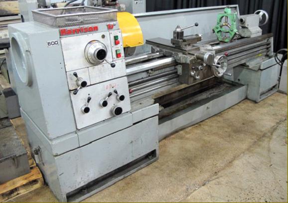
Early Harrison M450 badged as the "17-inch" for the American and Canadian markets

Early M450 with the European apron - carriage handwheel on the right-hand side

Early M450 with the American apron - carriage handwheel on the left-hand side


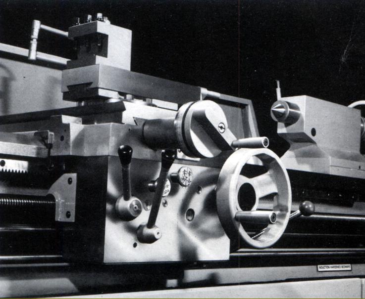
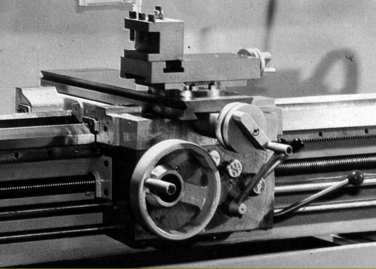
Carriage as fitted to late-model, straight-bed machines, with the hand-traverse hand on the left-hand front face of the apron and a single lever, pointing forwards in the middle, to select and engage power feeds. On the right-hand face of the apron, immediately below the standard-fit dial thread indicator was a gated spindle-control lever that provided electrical stop/start and forward/reverse functions; in addition, an emergency-stop button with a "power-on" light was fitted to the headstock whilst both the electrical isolator and coolant pump switch were mounted on the left-hand face of the stand.

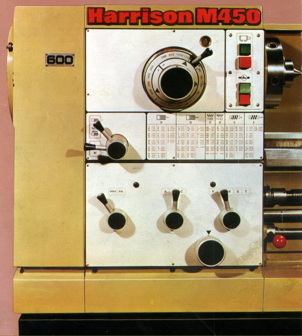
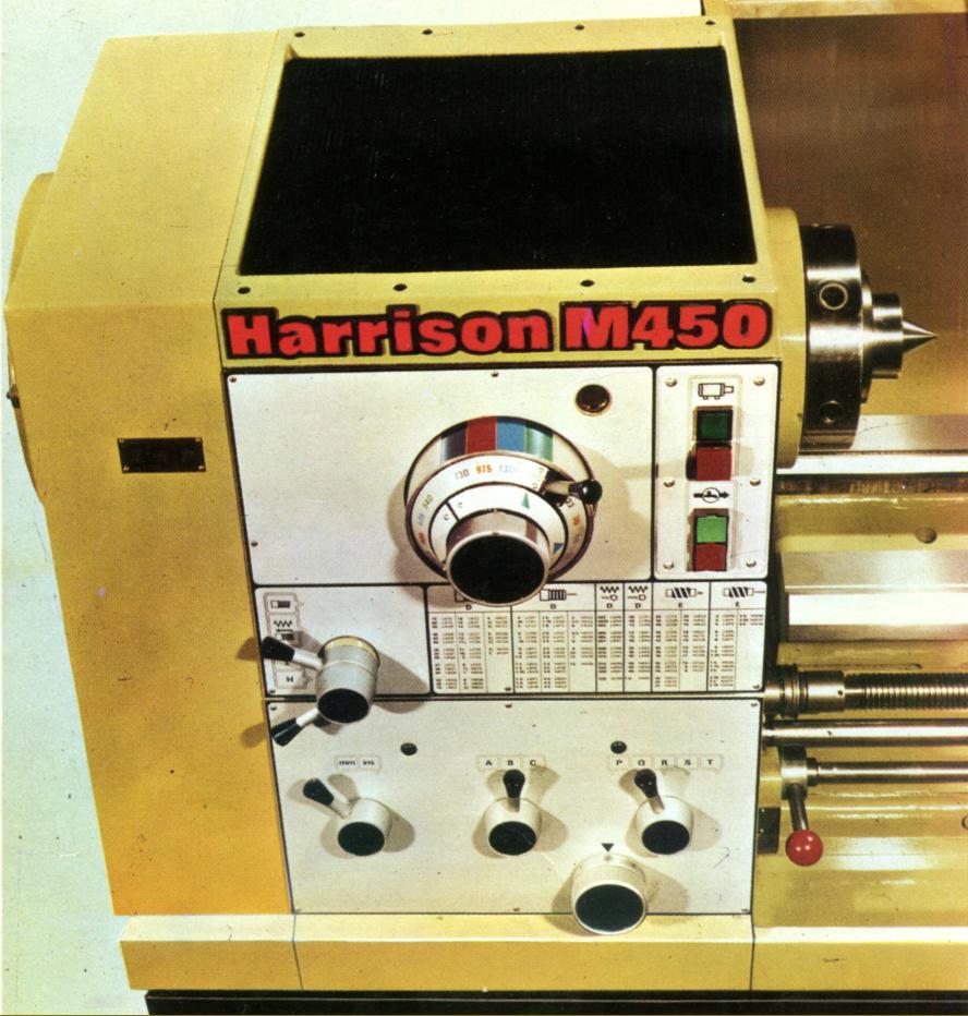
M450 late model: two concentrically mounted, rotary selectors that had unambiguous markings and positive indents selected the spindle speeds. Although electrical control of the spindle was primarily under the influence of a gated lever fastened to the right-hand face of the apron an emergency-stop button with a "power-on" light and stop/start controls were also was fitted to the headstock.   

Visible in this picture are the individual forward and reverse clutches on the rearmost (input) and the pipes supplying lubricant from the base-mounted pump and tank.


Apron as fitted to the later gap-bed models with the hand-traverse lever on the right-hand side of the front face and single-lever selection and engagement of the power feeds. The double-walled unit was formed to hold a quantity of oil within its base from where it could be pumped by hand to the various spindles and gears - and also to the bed and cross slide ways. On gap-bed machines the carriage-traverse handle (which could be disengaged when using power feeds) was positioned on the right-hand side of the apron, whilst straight-bed models it was on the left. The makers described the leadscrew nut as being of the "floating" type, used to ensure "maximum threading accuracy".

The oil-splash lubricated screwcutting and feeds gearbox was controlled by three smooth levers - which could be difficult to operate with oil hands - and a single rotary selector. Without changing or rearranging any of the end gears (changewheels) 78 metric pitches from 0.2 to 14 mm pitch, 79 English threads from 2 to 84 t.p.i, 47 Module pitches from 0.2 to 3.5 MOD and 47 Diametral from 8 to 64 DP.

The tailstock was robustly built and fitted with a 73 mm diameter (2.875") spindle with 155 mm (6.125") of travel and a No. 5 Morse taper. The spindle was engraved with ruler marks in either inch or metric graduations (or sometimes both) with a rotary micrometer dial fitted as standard.


The bed, with induction hardened V and flat ways was formed from a box section of high-quality cast iron with a maximum depth of 380 mm (beneath the headstock) and a width of 360 mm; heavy cross ribs braced the front and back faces and left clear spaces for swarf to fall through.

18 spindle speeds were provided from either 40 to 2000 rpm or, optionally, 31 to 1600 rpm from an easily-changed 7.5 kW (10 hp) motor fastened to an adjustable plate bolted to the back of the bed immediately below the headstock.
The link belt disappearing into the cabinet took power to the headstock lubrication pump.


An Operation, Maintenance & Parts Manual is available for the M450

M250   M300   M350 & 390  M400   M450   M500   M300 Photo Essay
   
VS330 (Export Model "AA")  Older Harrison Models 

Harrison 10AA (Chipmaster)

HARRISON M450 Lathe
email: tony@lathes.co.uk
Home   Machine Tool Archive   Machine-tools Sale & Wanted
Machine Tool Manuals   Catalogues   Belts   Books  Accessories