email: tony@lathes.co.uk
Home   Machine Tool Archive   Machine-tools Sale & Wanted
Machine Tool Manuals   Catalogues   Belts   Books  Accessories

HARRISON 17-inch Lathe

A Manual is available for the Harrison 17-inch lathe

Manuals are available for most Harrison lathes

Flat-belt Drive L2   An Original L5

Harrison Home Page   L5 Early Model   Later L5 9" & L5A 11-inch"   140
   
L5 Accessories   10-inch   Late 10" & 12" L6   Early 12" L6    Late L6 Mk. 3   

13" & 15" Late Models    13"   14"   16"   17"    Hydraulic Copy Lathes

Harrison Union Lathes   Models 155 and 165   Model 190

14", 16" & 17" Accessories

Newer Models:
AA-10 VS  VS330 & AA   M250   M300   M350 & 390   M400   M450   M500


Largest - and probably rarest of the Harrison lathe range - the 17-inch (8.5" centre height) was manufactured not by Harrison themselves but W. E. Sykes, production continuing until the mid 1960s. The true swing was 17.75 inches (441 mm) and the lathe admitted, in its standard bed form, 40 inches (1016 mm) between centres - but with the option available of longer beds able to accept material 53 inches, 66 inches and 79 inches long (1346 mm, 1676 mm and 2006 mm). The 3.125" (78 mm) bore spindle ran in a pair of opposed, pre-loaded Timken taper roller bearings at the front, an intermediate tapered roller race, a ball journal at the rear and carried an American-type L2 long-taper nose; five V belts transmitted power from a 10 hp 1500 rpm motor mounted inside the cabinet stand and the spindle was driven though its 12 speeds of  35, 54, 77, 115, 175, 210, 250, 320, 460, 680, 1050 and 1500 rpm. by a Matrix "reversing" clutch. The nickel-chrome headstock gears were shaved, induction hardened and honed and both they, and the spindle bearings, were provided with a pressurised oil supply via numerous small pipes; the oil flow could be checked though a small window in the front face of the headstock.
A substantial casting, 16 inches deep and 14 inches wide, the induction-hardened V bed was equipped as standard with a gap piece, though this was made deliberately shallow so as not to compromise beam strength; even so, with it removed, it was possible to turn a piece of material 26 inches in diameter and 9.5" deep (660 mm x 241 mm). The bed was supported on two massive cast-iron supports, one at each end of the bed, with a slide-out chip tray fitted as standard between them; the headstock-end unit carried the motor and electrical switch gear whilst the one at the tailstock end was used to house the coolant pump and tank. Two cast-in lifting lugs and a recessed locating bolt slot were provided at floor level on the outside face of each support. The spindle could be electrically controlled either from the headstock itself - or one of two control levers carried on a third shaft that ran the full length of the bed, below and parallel to the leadscrew and power shafts.
Using hardened and shaved gears running on ball-bearing-supported, multi-splined shafts, the screwcutting and feeds' gearbox was fed lubricant from a pressurised supply; it was able to generate 66 threads from 2 to 120 t.p.i (including the useful 11.5 and 27 and pipe-thread pitches) or, on the optional metric version, from 1/4 mm to 9 mm pitch. Sliding feeds varied from 0.0019" to 0.57" and surfacing feeds from 0.009" to 0.028" per revolution of the spindle; automatic stops were provided for the sliding feed. The arrangement of the main gearbox thread-selector handle on the early model was unusual in being arranged to rotate around a casting formed as a segment of a circle, the peripheral surface of which was machined with the necessary indent locations.
Doubled-walled, the early version of the completely-enclosed apron had all its shafts running in ball races while on later machines these were changed for  phosphor bronze bushes; the base held an oil supply where it was distributed by splash - a disappointing arrangement, for on a lathe of this size and strength a pumped feed, distributed around the apron and to the bed and cross slide would have been expected. The usual kind of push/pull button was fitted to select either power sliding or surfacing feed with the engagement lever positioned in the middle of the casting. A spindle-control lever was carried on the right hand face of the apron (and duplicated at the headstock end of the control rod) so allowing the operator to start, stop and reverse the spindle with safety when working away from the headstock on longer-bed versions. A thread-dial indicator was fitted as part of the standard equipment.
During its production run a series of changes were made to the machine, the most significant of which was a redesigned and much stronger cross and top slide assembly. The first model had a rather inadequately proportioned unit that flexed under the heaviest cuts; Harrison improved the situation considerably by employing an unusual design where two widely-spaced V-shaped, cross-slide ways were machined across the saddle with two long L-section plates (held by socket screws) to restrain the slide's vertical movement. With the slideways of the top slide arranged in an identical fashion the result was a significantly strengthened and more rigid assembly that gave a much smoother, more certain operation when working the lathe to its maximum capacity.
Locked to the bed by a single clamping pad (when some lathes of the same size used two), the tailstock had 6.5 inches travel with the 2.375" diameter barrel inscribed with 1/8" ruler graduations and fitted with a No. 4 Morse socket. Although a knock-out tange would have been preferable on such a large fitting, instead the centre was self-ejected as the barrel was drawn fully back into the casting.
The Harrison 17-inch was just under 9 feet long (2686 mm) and nearly 3 feet (858 mm) wide; it weighed 4,704 lbs (2133 Kg) and was delivered with a driver plate, travelling steady, 16" faceplate, two centres, a rotating centre, micrometer carriage stop, 4-way toolpost, a carbide cutting tool, instruction manual and the necessary spanners..


Harrison 17-inch - an early version with the narrow cross slide and  unusual thread-selector

Harrison 17-inch - 1965 Model

A rear view of the Harrison 17-Inch showing the deep bed,
rearward-pointing chip chutes and the slide-out chip tray.


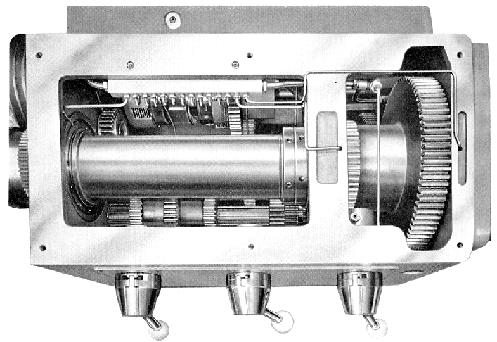
The nickel-chrome headstock gears were shaved, induction hardened and honed and both they, and the spindle bearings, were provided with a pressurised oil supply via numerous small pipes; the action of the oil pump could be checked though a small window in the front face of the headstock.

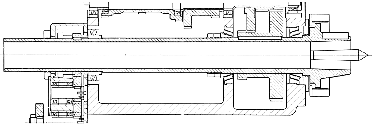
The 3.125" (78 mm) bore spindle ran in a pair of opposed, pre-loaded Timken taper roller bearings at the front, an intermediate tapered roller race, a ball journal at the rear and carried an American-type L2 long-taper nose.


The arrangement of the main gearbox thread-selector handle on the early model was unusual in being arranged to rotate around a casting formed as a segment of a circle, the peripheral surface of which was machined with the necessary indent locations. On the later model, illustrated left, this was changed to a more conventional rotating boss

The screwcutting gearbox had hardened and shaved gears running on ball-bearing-supported, multi-splined shafts and was fed lubricant from a pressurised supply; it was able to generate 66 threads from 2 to 120 t.p.i (including the useful 11.5 and 27 and pipe-thread pitches) or, on the optional metric version, from 1/4 mm to 9 mm pitch. Sliding feeds varied from 0.0019" to 0.57" and surfacing feeds from 0.009" to 0.028" per revolution of the spindle; automatic stops were provided for the sliding feed.

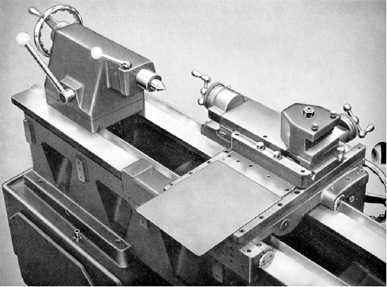
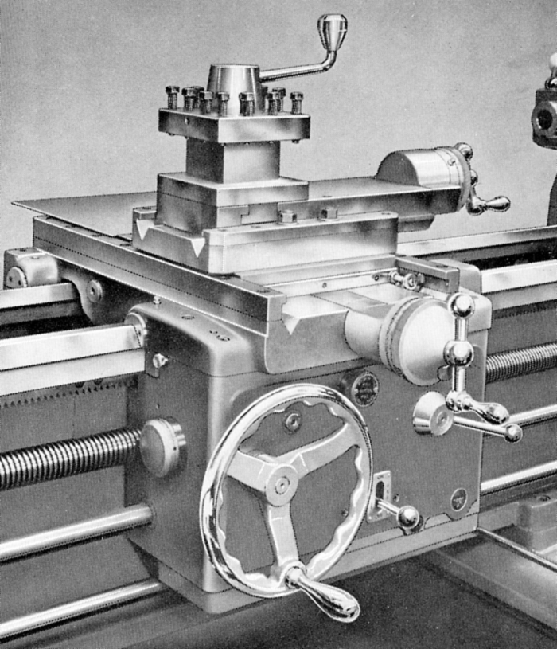
Above and below: The first model of the 17-Inch had a rather inadequately proportioned compound slide rest that flexed under the heaviest cuts; Harrison improved the situation considerably by employing an unusual design where two widely-spaced V-shaped, cross-slide ways were machined across the saddle with two long L-section plates (held by socket screws) to restrain the slide's vertical movement. With the slideways of the top slide arranged in an identical fashion the result was a significantly strengthened and more rigid assembly which gave a much smoother, more certain operation when working the lathe to its maximum capacity.


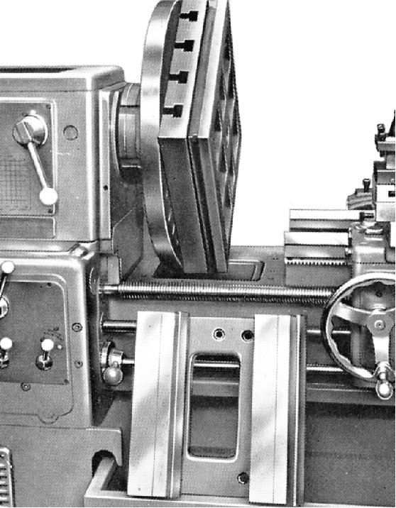
A detachable gap piece was fitted to the bed and with this section removed a
piece of material 26 inches in diameter and 9.5" deep could be machined.

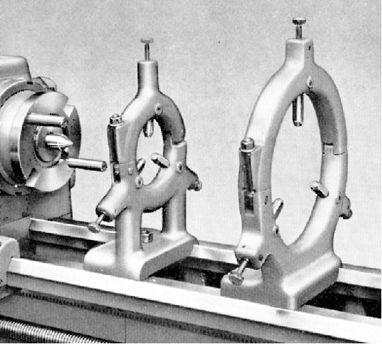
Two sizes of fixed steady were offered, both with proper screw-adjusted fingers


A Manual is available for the Harrison 17-inch lathe

Manuals are available for most Harrison lathes

Flat-belt Drive L2   An Original L5

Harrison Home Page   L5 Early Model   Later L5 9" & L5A 11-inch"   140
   
L5 Accessories   10-inch   Late 10" & 12" L6   Early 12" L6    Late L6 Mk. 3   

13" & 15" Late Models    13"   14"   16"   17"    Hydraulic Copy Lathes

Harrison Union Lathes   Models 155 and 165   Model 190

14", 16" & 17" Accessories

Newer Models:
AA-10 VS  VS330 & AA   M250   M300   M350 & 390   M400   M450   M500

HARRISON 17-inch Lathe
email: tony@lathes.co.uk
Home   Machine Tool Archive   Machine-tools Sale & Wanted
Machine Tool Manuals   Catalogues   Belts   Books  Accessories