|
Home Machine Tool Archive Machine-tools Sale & Wanted Graduate Lathes Home Page Harrison Jubilee Lathe Harrison "Union" Lathes Harrison Home Page |
|
|
||
|
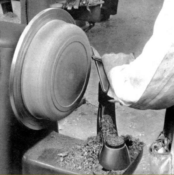
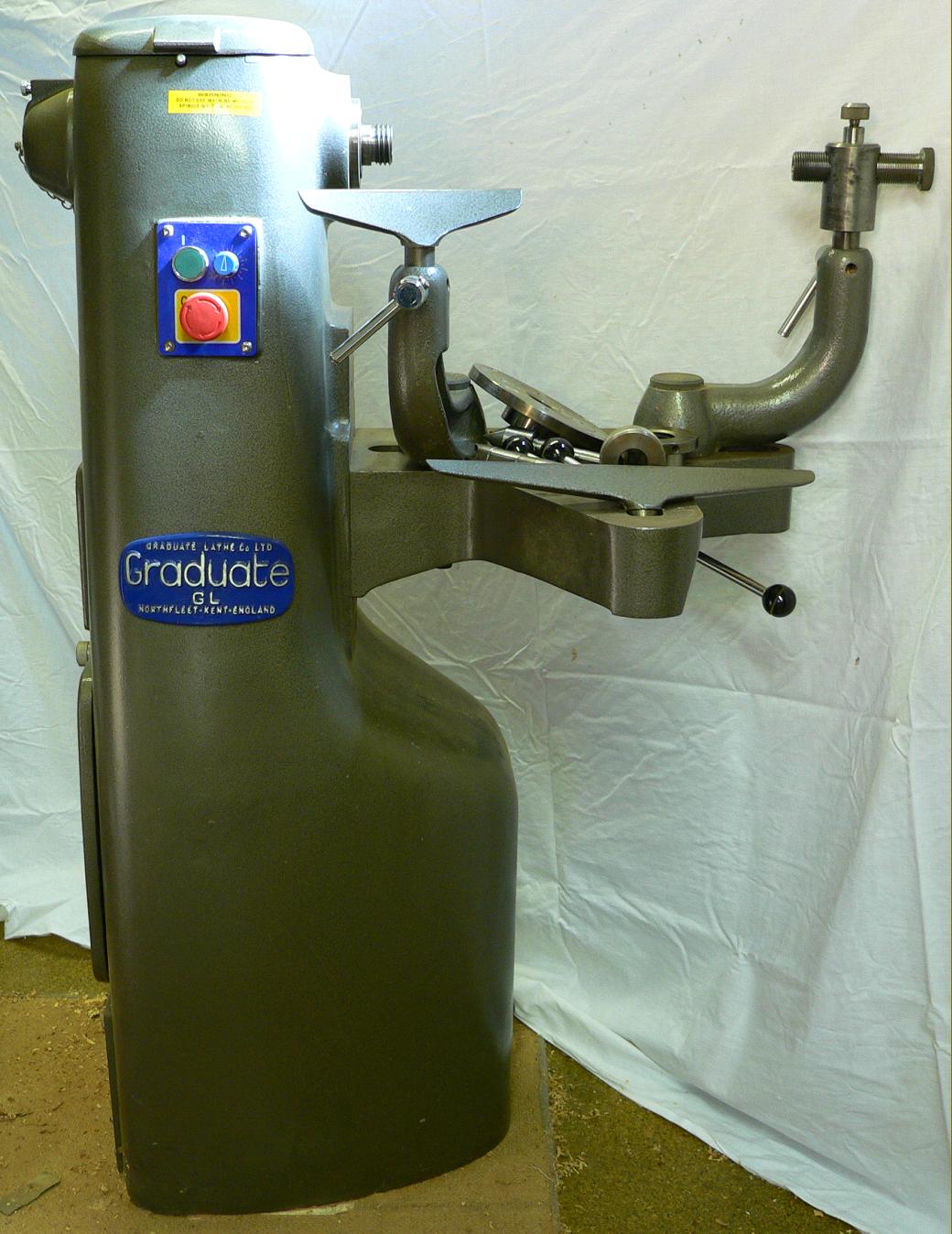
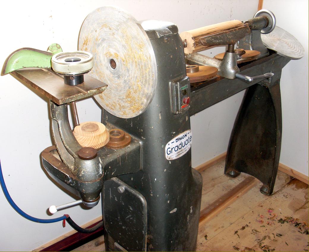
Compared to attempting the same task on a Chinese-made lathe made of folded tin plate, bowl-turning on a machine as solid as the Graduate is a pleasure - and achieved with a greater degree of safety and comfort as the work responds directly to pressure from the tool instead of flexing away from it |
||
|
|
|
|
|
|
|
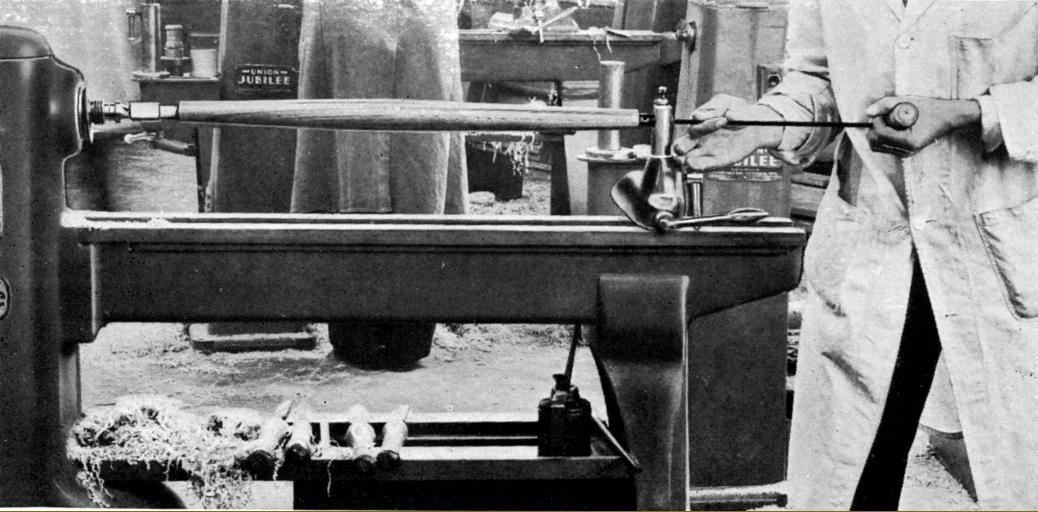
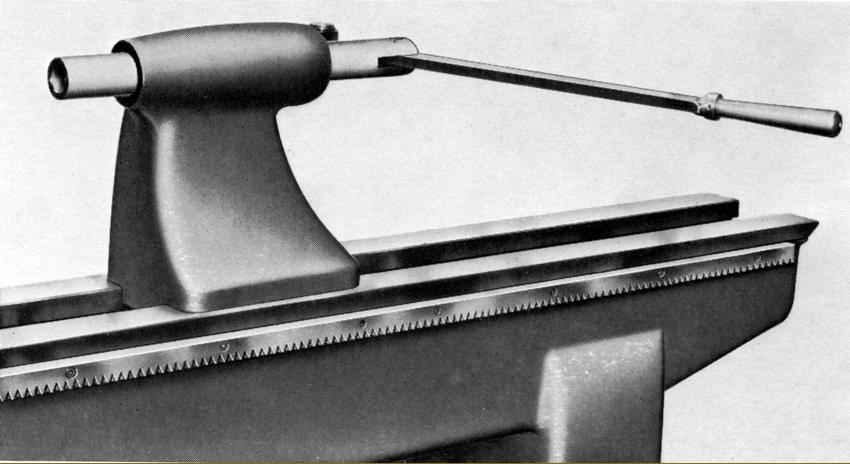
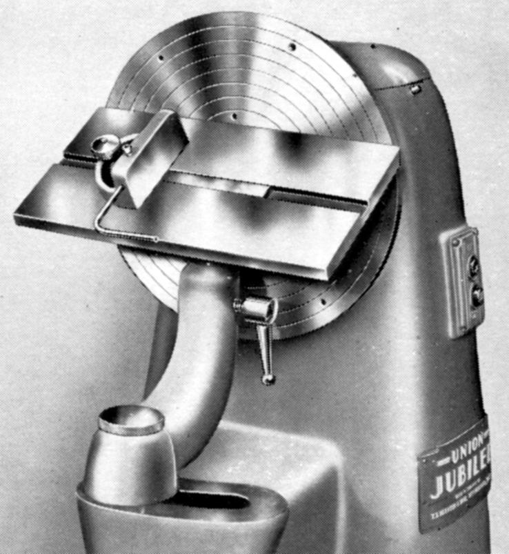
is fitted with the swan-neck attachment to allow sort, between-centres turning |
|
|
|
and a handbook for the older Jubilee email: tony@lathes.co.uk Home Machine Tool Archive Machine-tools Sale & Wanted |