|
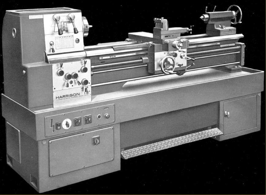
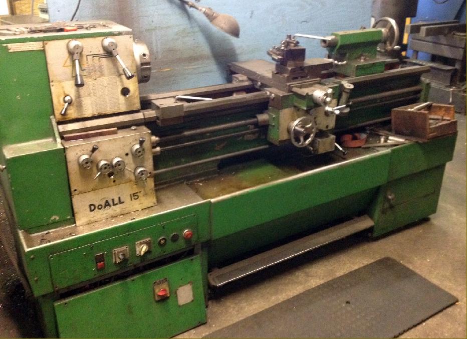
Home Machine Tool Archive Machine-tools Sale & Wanted - late 1960s to early 1970s & also badged as a "DoAll" - Harrison Home Page L5 Early Model Later L5 9" & L5A 11-inch" 140 L5 Accessories 10-inch Late 10" & 12" L6 Early 12" L6 Late L6 Mk. 3 13" & 15" Late Models 13" 14" 16" 17" Hydraulic Copy Lathes Harrison Union Lathes Models 155 and 165 Model 190 14", 16" & 17" Accessories |
|
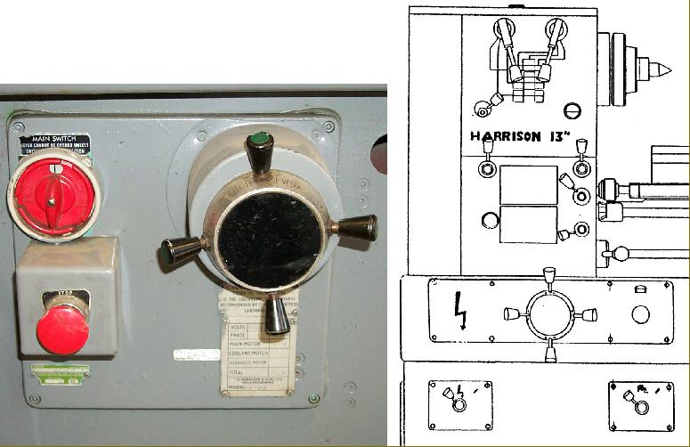
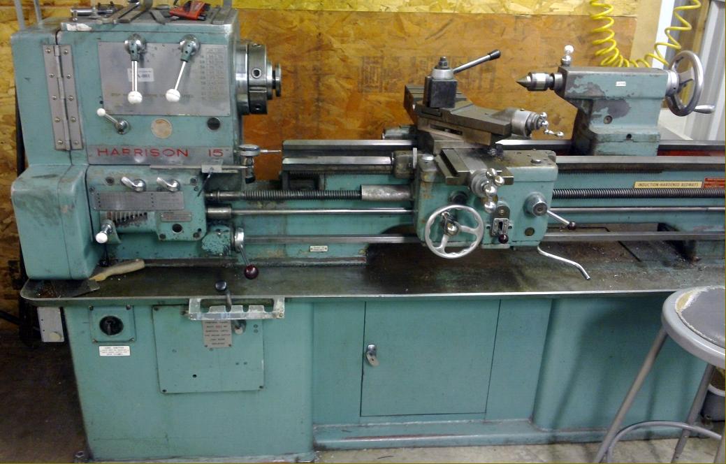
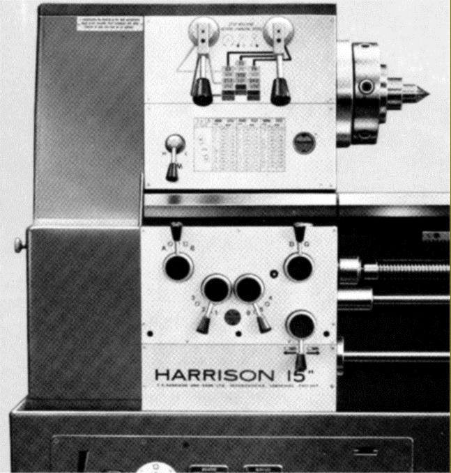
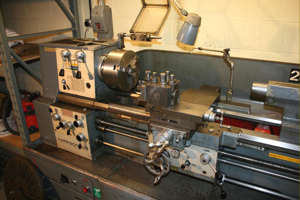
If the nameplate is missing and you don't have a ruler to measure the centre height, the 15-inch Version (Model 190) model can be instantly identified by its long foot-brake, an item missing from the 13-inch (Model 165). |
|
|
|
|
|
|
|
|
|
|
|
|
||
|
Harrison Home Page L5 Early Model Later L5 9" & L5A 11-inch" 140 L5 Accessories 10-inch Late 10" & 12" L6 Early 12" L6 Late L6 Mk. 3 13" & 15" Late Models 13" 14" 16" 17" Hydraulic Copy Lathes Harrison Union Lathes Models 155 and 165 Model 190 14", 16" & 17" Accessories - late 1960s to early 1970s - |