|
Home Machine Tool Archive Machine-tools Sale & Wanted An Operation, Maintenance & Parts Manual is available for the VS330 VS330 (Export Model "AA") Older Harrison Models Harrison 10AA (Chipmaster) |
|
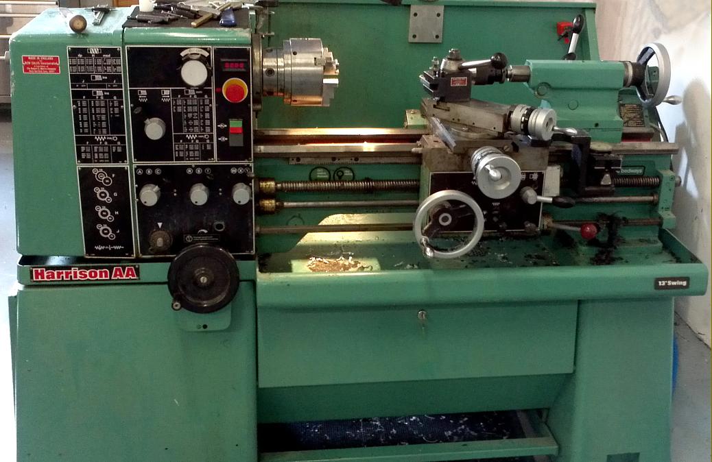
With a 330 mm (13") swing and admitting 635 mm (25") between centres, the Harrison VS330TR was a small, very well specified toolroom-quality lathe constructed to International Precision Lathe Standards ISO R1708 and BS 4656 (UK) and DIN 8605 (Germany). For export markets it was also listed as the Model AA, and replaced the previous variable-speed drive Harrison lathe, a re-badged Colchester Chipmaster. The VS330's main feature was a quiet-running mechanical variable-speed drive unit that, in combination with gears and an "inverted chain" drive in the headstock, gave three separate overlapping speed ranges which equated to: 35 to 180 rpm, 180 rpm to 500 rpm and 500 to 3000 rpm. A 2.2 kW (3 hp) 1000 rpm totally-enclosed, fan-cooled motor was bolted, in the usual Harrison fashion, to an adjustable plate fastened to the back of the bed behind the headstock with (in a very compact arrangement) one variable-speed drive pulley fitted to the motor's shaft and the other to the input shaft of the headstock. The 110-volt electrical-control equipment was neatly built into a single compartment on the left-hand end of the stand, access being through a door protected by a mechanically interlocked isolator switch. The lathe was not fitted with a clutch, but relied instead upon direct on-line starting through forward and reverse contactors with an 'emergency stop' available though both a button mounted on the headstock and a full-length foot bar between the cabinet feet; the main spindle stop, start, forward and reverse control was by a safety-gated lever fastened to the right-hand face of the apron and working a long control rod set below and parallel to the leadscrew and powershaft. |
|
The 330 mm (13") swing by 635 mm (25") between centres Harrison AA was a small, very well specified toolroom-quality lathe constructed to International Precision Lathe Standards ISO R1708 and BS 4656 (UK) and DIN 8605 (Germany); it replaced the previous small variable-speed drive Harrison lathe, the 10-AA, that had been a re-badged Colchester Chipmaster. |
|
The carriage was constructed along traditional Harrison lines with a full-length cross slide and a top slide that swivelled through 360 degrees; both the saddle-to-bed fitting, and the cross slide were fitted with proper taper-key gib strips that allowed very fine control over their free movement and, as standard, the compound slide feed screws were fitted with dual-reading English/metric micrometer dials. The cross-feed screw nut was equipped with the same type of effective anti-backlash adjustment employed for many years on all the larger Harrison (and Colchester) lathes. |
||
|
A 2.2 kW (3 hp) 1000 rpm totally-enclosed, fan-cooled motor was bolted, in the usual Harrison fashion, to a simply-engineered adjustable plate fastened to the back of the bed behind the headstock with (in a very compact arrangement) one variable-speed drive pulley fitted to the motor's shaft and the other to the input shaft of the headstock. The intermediate drive gears to the feeds and screwcutting gearbox were in a quiet-running, non-metallic material which required no lubrication. |
||
|
Gears, together with an "inverted chain" drive in the headstock and in combination with a quiet-running mechanical variable-speed drive unit, gave three separate overlapping speed ranges which equated to: 35 to 180 rpm, 180 rpm to 500 rpm and 500 to 3000 rpm. |
||
|
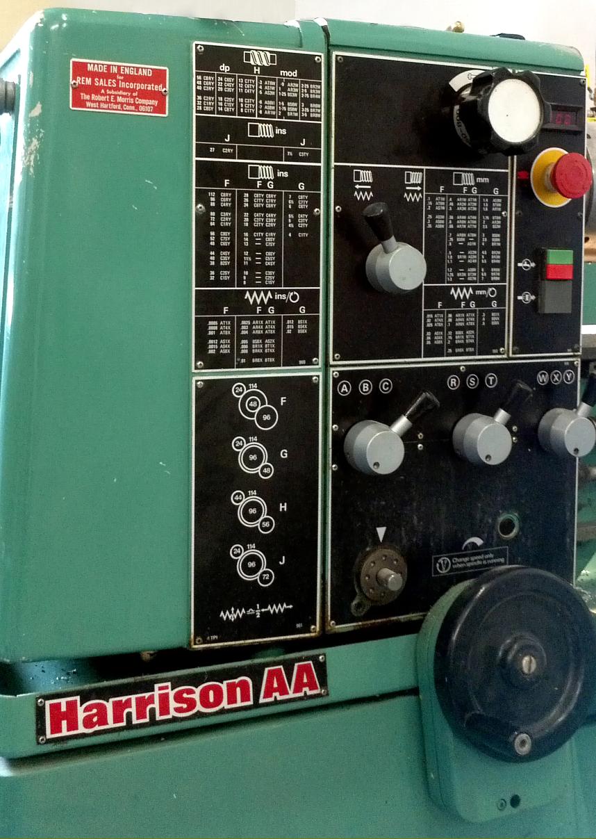
The screwcutting gearbox followed modern practice in being constructed from a totally enclosed, one-piece casting that held a supply of lubricant in the base from where it was distributed by splash. The gears were all induction hardened with the threading and feed ranges selected by three levers and an 8-position dial; a total of 39 metric, 35 English, 18 Module and 18 Diametrical pitches could be achieved by moving the control levers and either rearranging the standard changewheel set - or employing some of the extra non-metallic (hence quiet-running) gears which were supplied with the machine in order for it to achieve its full threading range. |
|
With no gearlevers to set, or belts to move - and hence no mechanical indication of the spindle speed - some form of digital speed readout was required; unfortunately, instead of being a large, clear unit angled so that the operator could read it without hesitation, it was a rather tiny, insignificant affair tucked away in the top right hand corner of the headstock's front face. |
|
The straight bed (there was no option of a gap) was induction hardened and fastened to a heavy-gauge sheet-metal stand which was fitted not only with the usual splash back, but a locking tool cupboard as well. |
||
|
The 110-volt electrical control equipment was neatly built into a single compartment on the left-hand end of the stand, access being through a door protected by a mechanically interlocked isolator switch. The lathe was not fitted with a clutch, but relied instead upon direct on-line starting through forward and reverse contactors with 'emergency stop' available though a button mounted on the headstock and a full-length foot bar between the cabinet feet; the main spindle stop, start, forward and reverse control was by a gated lever fastened to the right-hand face of the apron. |
|
to long grooves in the V ways of the saddle. |
||
|
|
||
|
The carriage was constructed along traditional Harrison lines with a full-length cross slide and a top slide that swivelled through 360 degrees; both the saddle-to-bed fitting, and the cross slide were fitted with proper taper-key gib strips that allowed very fine control over their free movement and, as standard, the compound slide feed screws were fitted with dual-reading English/metric micrometer dials. The cross-feed screw nut was equipped with the same type of effective anti-backlash adjustment employed for many years on all he larger Harrison (and Colchester) lathes. |
||
|
With no gearlevers to set, or belts to move - and hence no mechanical indication of the spindle speed - some form of digital speed readout was required; unfortunately, instead of being a large, clear unit angled so that the operator could read it without hesitation, it was a rather tiny, insignificant affair tucked away in the top right hand corner of the headstock's front face. |
||
|
VS330 (Export Model "AA") Older Harrison Models Harrison 10AA (Chipmaster) Home Machine Tool Archive Machine-tools Sale & Wanted |