 |
|
|
|
|
|
|
|
|
|
|
|
|
|
|
|
|
|
|
|
|
|
|
|
|
|
|
|
|
|
|
|
|
|
|
|
|
|
|
|
|
|
|
|
|
|
|
|
|
|
|
|
|
|
|
|
|
|
|
|
|
|
|
|
|
|
|
|
|
|
|
|
|
|
|
|
|
|
|
|
|
|
|
|
|
|
|
|
|
|
|
|
|
|
|
|
|
|
|
|
|
|
|
|
|
|
|
|
|
|
|
|
|
|
|
|
|
|
|
|
|
|
|
|
|
|
|
|
|
|
|
|
|
|
|
|
|
|
|
|
|
|
|
|
|
|
|
|
|
|
|
|
|
|
|
|
|
|
|
|
|
|
|
|
|
|
|
|
|
|
|
|
|
|
|
|
|
|
|
|
|
|
|
|
|
|
|
|
|
|
|
|
|
|
|
|
|
|
|
|
|
|
|
|
|
|
|
|
|
|
|
|
|
|
|
|
|
|
|
|
|
|
|
|
Founded in 1862 and originally of 222 Moody Street, Waltham, New England, U.S.A., the Stark Company is an important name in the history of American close-tolerance engineering - and one that survived into the 1950s when they were still making a well-developed version of their original machines (the Company was incorporated in 1918 becoming Stark Tool Co. Inc). The firm were almost certainly the originators of the "precision bench lathe" - as eventually made by a variety of firms in the U.S.A. including: American Watch Tool Company, Arrow, B.C.Ames, Bausch & Lomb, Benson, Boley, Bottum, Boxford, B.W.C., Carstens, Cataract, Cromwell, Crystal Lakes, CVA, Derbyshire, Elgin, Hardinge, Hjorth, Juvenia, Karger, Leinen, Levin, Lorch, Mikron, W.H.Nichols, Potter, Pratt & Whitney, Rambold, Rebmann, Remington, Rivett, Saupe, Schaublin, See (FSB), Sloan & Chace, Smart & Brown, T & L.M., U.N.D., Van Norman, Wade, Waltham Machine Works, Weisser, Wolf Jahn and (though now very rare), Frederick Pearce, Ballou & Whitcombe, Sawyer Watch Tool Co., Engineering Appliances, Fenn-Sadler and the "Cosa Corporation of New York."
They were also widely copied in Europe and developed as, amongst others, the Schaublin, Lorch, G.Boley, Wolf Jahn, Carstens, Mikron and Simonet.
Stark's claim as originators of the "precision bench lathe" type was bold and unequivocal (and printed on all their sales catalogs) with the first examples built by John Stark personally, in 1862, well before any of his competitors - who were also mostly from the Waltham area. A special section of the Archive, assembled from literature of the 1870s, has been devoted to these very early and important Stark machines. The company were also famous for their watchmaker's lathes and also built a wide range of specialised machinery and tools for use in watch and clock-manufacturing and repair plants.
Eventually to be made in six models - based around four different beds and headstocks - the Stark precision bench lathes were available with swings varying from 5.875 " to 12" and collet capacities from 0.25" to 1.25". Incredibly, production continued well into the 1950s, with small advertisements for their Series 400 and variable-speed underdrive No. 4 and 41/2 and bench-mount No. 3 precision plain-turning lathes making an incongruous appearance in the machine-tool trade press. Although Stark have now disappeared the American tradition of very high quality precision plain-turning lathes is continued into the 21st century by both the Derbyshire and Levin companies.
The basis of all early models was a bed with bevelled edges and a single central T slot that located the headstock, tailstock and fittings such as a compound slide rest or hand T-rest. However, at the heart of the lathe's accuracy was a superbly-made, high-speed headstock spindle and bearing assembly based on a design already standardised for watch lathes where a hardened, ground and lapped spindle ran in glass-hard steel bearings - a system which represented the very best use of the materials and manufacturing techniques available in the late 1800s. The spindle and bearings were originally advertised as being manufactured from "English steel" - almost certainly a reference to crucible steel, the contemporary (Huntsman) method of producing small quantities of high-quality metal with tightly-controlled properties. The headstock design continued unchanged until the late 1920s when the option of precision ball bearing spindles was offered, at first to special order - and then only recommended by the makers for applications where very high speeds had to be sustained for long periods.
Machined with both an external thread and an internal taper, the Stark headstock spindle accept draw-in collets closed by either the action of either a simple "screw-in" draw tube or, for production work, a lever-operated closer. Unlike some makers, who neglected to provide one, the thread allowed chucks, faceplate and other fittings to be mounted. A 3-step flat-belt headstock pulley was arranged so that the smallest diameter was immediately behind the spindle nose - on an ordinary lathes it is usually the opposite way round - so allowing the all-important front bearing to not only be made as large as possible, but also to be surrounded by a greater mass of supporting metal. The design also made it easier to provide one or more rings of indexing holes that could be engaged by a pin passing through a boss cast into the left-and headstock wall - in exactly the same manner as employed on a watchmaker's lathe.
Held to the bed by a T-headed bolt engaging in a slot running down the underside of the cross slide, the slide rest assembly was beautifully-made, superbly-finished and with conical-face micrometer dials. Most Stark compound assemblies had a T-slot machined into the right-hand face of the cross slide so that front and rear stops could be mounted to make repetition work easier. A feature unique to Stark (on later lathes) was the mounting of the ring carrying the micrometer-dial zero mark on two rods attached to the inner casting - a feature not always visible in photographs
Like that fitted to most precision lathes, the tailstock carried a barrel (spindle) that was fully supported by the surrounding casting, even when fully extended - although this feature was missing from the very earliest lathes.
As John Stark was also prominent in the design and development of watchmakers' lathes, and manufacturing machinery, he may well have invented, amongst other items, the split collet (or "chuck" as they were originally known). Research into early Stark watchmakers' lathes and attachments is proving particularly difficult and if any reader can help with catalogs, photographs of lathes, or other information the writer would be very pleased to hear from you..
|
|
|
|
|
|
|
|
 |
|
|
|
|
|
 |
|
|
|
 |
|
|
|
|
|
|
|
|
|
|
John Stark Senior: Originator and Pioneer manufacturer of the "Spring Chuck" lathe.
|
|
|
|
|
|
|
|
John Stark Junior, son of John Stark Senior
|
|
|
|
|
|
|
|
|
|
|
|
|
|
 |
|
|
|
|
|
|
A typical Stark lathe, a No. 4 Precision Bench with a 38" long bed with 20" between centres and a swing of 9". The collet capacity of the later No. 4 lathes was increased from 0.75 " to a full 1". Note the T-slot machined into the right-hand face of the cross slide.
|
|
|
|
|
|
|
|
|
|
|
 |
|
|
|
|
|
|
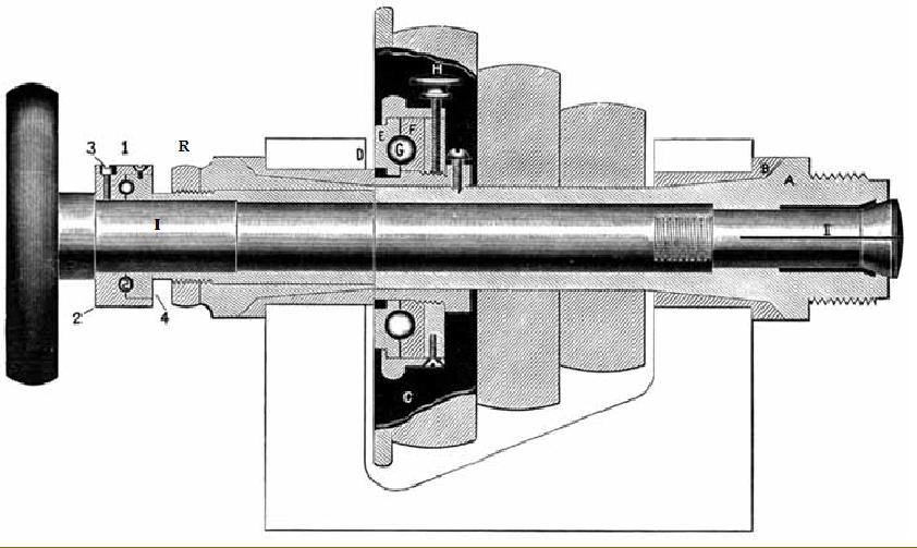
The Early Stark headstock - like that of all early Precision Bench Lathes - used a developed version of the design originally standardised for watch lathes where a hardened, ground and lapped spindle ran in glass-hard steel bearings - the very best combination of materials and manufacturing techniques available in the late 1800s and originally advertised by Stark as being manufactured from English steel.
The version of the Stark headstock illustrated left took the design one stage further with the inclusion of a ball-bearing race to absorb spindle end thrust when drilling from the tailstock - the design being patented under No. 388,927 in September, 1888.
In order to set the thrust bearing - and so relieve the plain front bearing B of excess longitudinal loads - the normal adjustment of the spindle bearings by a screwed ring at R was first carried out. The bearing cap C was then rotated until it brought the outer race of the bearing E into contact with the headstock casting at D; the milled-edge locking screw H - which passed through the assembly to press against the adjusting thread - could then be tightened to hold the setting. The result was that end loadings were taken on the plate E, which remained stationary, whilst the inner race F rotated with the spindle.
Another patented arrangement of a ball race to take the end thrust on the collet tube (I) was also used on this headstock.
|
|
|
|
|
|
|
|
 |
|
|
|
 |
|
|
|
|
|
|
|
Stark No. 4 Lathe on the maker's superb iron-framed oak cabinet stand with self-contained drive system; note the very wide flat belt round the motor pulley - necessary in order to obtain sufficient grip on a small diameter. The countershaft inside the stand carried three wide pulleys of different diameters with each driving up to its own fast-and-loose pulley on the overhead countershaft. The right-hand outer pulley within the stand provided a fast speed range, the outer left-hand pulley a slow range. The central pulley, mid-way in size between the outer pair, was arranged to provide a reverse drive - by the traditional means of putting a 180-degree twist in the belt. Any of the drives could be instantly engaged and disengaged by treading on one of three pedals which were connected, by wires, to the belt-shifting forks on the overhead countershaft.
Besides the lathe spindle, the countershaft also powered - via a 2 : 1 flat-belt pulley system at its right-hand end - a parallel shaft designed to provide a high-speed drive to milling cutter and grinding attachments held in the lathe's toolpost. The cost of cabinet and drive system would have been several times that of the basic lathe.
|
|
|
|
|
|
|
|
|
|
|
|
|
|
|
|
Stark's range of Precision Bench lathes consisted of six different models based around four different beds and headstocks:
No. 2 - 16" or 22" long bed with 6" or 12" between centres, a 57/8" swing and a collet capacity of 0.25"
No. 3 - a 32" long bed with 18" between centres, a 7" swing and a collet capacity of 0.375"
No. 31/2 - same size as the No. 3, but with a reduced collet capacity of 0.5"
No. 4 - a 38" bed with 20" between centres, a 9" centre height and a collet capacity of 0.75"
No. 41/2 - identical to the No. 4 but with an increased collet capacity of 1"
No. 5 - the largest lathe in the range with a 40" bed, 20" between centres, a swing of 12" and a collet capacity of 1.25"
Collets:
Allowing for the fact that many Stark lathes would have been supplied with headstock spindles adapted to take a customer's already-in-use collet sets the following guide should be accurate:
Stark 3 lathe collets (marked 3SS) had a maximum through bore of 0.375", a shank of 0.590" and a thread of 0520" x 26 t.p.i.
Stark 31/2 lathes collets (marked 32S) took round material to a maximum diameter of 0.5", square to 11/32" and hexagon to 7/16". The collet shanks were 0.703" in diameter with a 0.698" x 24 t.p.i. thread and an overall length of 2.565".
Stark 4 lathe collets (Marked 4S) had a maximum bore ¾", a shank diameter of 0.998" and a thread of 0.993" x 20 t.p.i
Stark collets all have a head angle of 5 degrees whilst another useful identifying feature is mark (not always present) "STCo".
Even without its maker's name plate a Stark lathe is easy to recognise - the feet on the double pedestal models being a distinctive elliptical shape.
|
|
|
|
|
|
|
|
 |
|
|
|
|
|
|
Stark No. 2 "Manufacturing Lathe" - a small cantilever-bed machine supplied with either a 16" or 22" long bed with 6" and 12" between centres respectively. The swing was 57/8" swing the maximum collet capacity 0.25". This accurate bench lathe was capable of being converted to light manufacturing use and was also available with a supporting foot at the tailstock end of the bed when heavy-duty use was envisaged.
|
|
|
|
|
|
|
|
 |
|
|
|
|
|
|
Stark No. 3, 31/2, 4 and 41/2 Bench Lathe with compound slide rest. This 1920s machine has a screw-feed tailstock barrel which was fully supported by the surrounding casting even at the extremes of its travel.
|
|
|
|
|
|
|
|
|
|
|
|
|
|
|
|
|
 |
|
|
|
|
|
|
Stark No. 5 Bench Lathe with compound slide rest. A much heavier lathe for larger precision jobs.
|
|
|
|
|
|
|
|
|
|
|
 |
|
|
|
|
|
Stark No. 3 Spring-bind lathe for rapid collet work. The headstock pulley could be stopped - and the collet opened - by a single movement on a foot-operated pedal.
This early "production" system is still in use today for small batch work and offered by the American firm of Derbyshire on their range of precision lathes.
|
|
|
|
|
|
|
|
|
|
|
|
|
|
 |
|
|
|
|
|
Stark No. 3, 31/2, 4 and 41/2 Bench Lathe with an Automatic Turret (with six independently adjustable tool depth stops) a Lever-operated Collet Closer and a Cut-off and Forming Slide Rest.
|
|
|
|
|
|
|
|
|
|
|
|
|
|
 |
|
|
|
|
|
Stark No. 5 Screw Machine (capstan)- the largest model in the range - with a 40" long bed offering 20" between centres and a swing of 12"
Designed for the manufacture of screws and bolts with a through collet capacity of 1.25"
|
|
|
|
|
|
|
|
|
|
|
|
|
|
 |
|
|
|
|
|
Photograph of a Stark which hints at the superb finish of the original machines. If anyone has a set of pictures of a well-finished Stark of any age or size, the writer would be very interested to hear from you.
|
|
|
|
|
|
|
|
|
|
|
|
|
|
 |
|
|
|
|
|
A stark with its headstock pulley arranged in reverse of that normally found and with an unusual mounting on the flat end of the lathe bed - a small compound table set up for use as a horizontal milling machine complete with a swivel dividing head and tailstock - and with the cutter carried on an extension of the headstock spindle; the bevel-gear operated knee elevation was a particularly compact and well-executed design. The original version of this attachment can be seen here.
|
|
|
|
|
|
|
|
|
|
|
|
|
|
 |
|
|
|
|
|
|
The Stark lathe, like many in its class, could be fitted with traditional "chase screwcutting" where a T slot, which ran down the back of the bed, held supports which carried a sliding shaft to which was attached a toolholder. Above the shaft, at the headstock end of the lathe, was a "master thread" driven by a selection of gears from the end of the main spindle in such a way that its threading range was extended by a multiple of six.
A follower (with an insert carrying a few threads of the same pitch) pressed against the master thread and transmitted its form to the workpiece via the sliding shaft and a threading tool held in an adjustable slide rest.
Whilst this system produced absolutely accurate threads, and was especially suited to delicate operations on thin-wall tubes used to construct such items as microscopes, the length of thread that could be cut, and the number of threads per inch or mm, depended upon the availability of the appropriate master.
Similar arrangements can be seen on the pages devoted to the American makers Goodell-Pratt, Pratt & Whitney, Ames, Potter, Waltham Machine Works and Wade.
|
|
|
|
|
|
|
|
 |
|
 |
|
|
|
|
|
|
|
|
|
|
|
Swing Tailstock or Jewelling Tool:
Originally designed for rapidly opening holes in clock plates to receive jewels the unit was developed to enable it to accurately finish bore holes to receive parts that might vary slightly in diameter from piece to piece.
The aim of the device was to ensure the highest possible accuracy by holding, between a gauge plate and gauging finger at the top of the unit, the actual jewel (or lens, etc.) that was going to be fitted into the bored hole. If the setting instructions were followed the bored hole would be exactly the same size as the part held by the gauging device.
|
|
|
|
|
|
|
|
|
|
|
|
|
|
|
|
|
Filing and Sawing Attachment:
This useful device (full-sized versions were a popular addition to toolrooms until the 1960s) clamped to the bed and was driven by an eccentric held in the end of the headstock spindle.
Files and saws up to 4" long could be held in the top yolk - with the possibility of mounting longer but unsupported ones by using a holder in the lower slide.
The table was 4.5" in diameter and provided with a scale marked in degrees so that it could be set over at any angle.
Fittings were available to mount the unit on all but the
|
|
|
|
|
|
|
|
|
|
 |
|
|
|
|
|
Stark No. 4 Lathe with lever-action collet closer, lever tailstock and a lever-action cut-off or "Forming Slide".
|
|
|
|
|
|
|
|
|
|
|
|
|
|
 |
|
|
|
|
|
Stark No. 4 Lathe with Draw-in collet closer, tapped-hole faceplate, compound slide rest with a boring-tool holder - and a tailstock fitted with a barrel depth stop. The bed, with the T-slotted front is of the type to accept the "Chase" screwcutting attachment whilst the left-hand foot, with its braced extension to the end of the bed, shows that this model was also equipped to mount the milling or filing attachments.
|
|
|
|
|
|
|
|
|
|
|
|
|
|
 |
|
|
|
|
|
Compound Slide Rest fitted with the Combination Tool Post. Note the T-slot machined into the full length of the cross slide - this was to mount front and rear screw-adjustable stops (the abutment can be see between the gib-strip adjustment screws). A feature unique to Stark was the mounting of the ring carrying the micrometer-dial zero mark on two rods attached to the inner casting - they can just seen (on both cross and top slide) in the pictures above and below.
|
|
|
|
|
|
|
|
|
|
|
|
|
|
 |
|
|
|
|
|
Compound Slide Rest fitted with the Plain Tool Post.
The various sizes of compound slide rest are listed below and should enable easy identification of units that have become separated from their original lathe.
|
|
|
|
|
|
|
|
|
|
|
|
|
|
|
|
|
 |
|
 |
|
|
|
|
|
Combination Tool Post:
This was a well-made unit with provision for holding round as well as square and rectangular-section tools. The round-tool holding collet was fixed into an eccentric bush to provide a small range of vertical adjustment.
Four different models were made: the smallest code named CLIFF was for the tiny No.2 lathe and accepted tools up to 1/4" square and 5/16" round. The next version, for the No.3 and 31/2 lathes, had the same capacity and was given the accessory code CLING. Somewhat larger was that for the No. 4 and 41/2 lathes which took 3/8" round and 5/16" square tools and was listed as the CLIPP. The largest, which weighed a substantial 4 lbs and took 3/8" round and 1/2" square tools, was code-named CLOAK and fitted the large No. 5 lathe.
|
|
|
|
|
|
|
|
|
|
|
|
|
|
Plain Tool Post:
The Stark toolpost was carefully designed so that the stud which bore against the tool to clamp it down was not part of the tightening screw. The rocker and other parts were pinned in place - a thoughtful touch to help keep things in place and reduce the amount of time spent looking for misplaced components.
Four different models were available to fit the range of lathes:
CLEFT fitted the No. 2 (3/16" tools)
CLERK the No. 3 & 31/2 (5/16" tools)
CLEVE the No. 4 & 41/2 (3/8" tools)
CLICK the No. 5 (1/2" tools).
|
|
|
|
|
|
|
|
|
|
|
|
|
|
|
|
|
|
|
|
|
|
|
 |
|
|
|
|
|
|
|
|
Ball-turning
Tool Slide. Designed for the easy manufacture of spheres up to 4" in diameter.
|
|
|
|
|
|
|
|
|
|
|
|
|
 |
|
|
 |
|
|
|
|
|
|
|
|
Screw Slotting Attachment for use on lathes with a 7" to 9" swing.
This device was intended for production purposes where quantities of small screws need to be slotted.
The screws were held between two jaws which, being mounted on a swivel base, could be swung away for loading and unloading. An adjustable stop controlled the depth of cut.
|
|
|
|
|
|
|
|
|
|
|
|
Internal Grinding Attachment:
This attachment, although designed specifically for internal work, could also be used for light-duty external grinding. The unit (normally powered by a round rope driven from an overhead countershaft) clamped into the position usually occupied by the tool post - and was therefore adjustable through all the normal movements and angles associated with the compound slide. The spindle, manufactured from hardened, ground and lapped steel, was 7 inches long and ran in straight bearings of the same material; a fibre knob on its end was used to apply the longitudinal feed by hand. The unit was adjustable through a small range for precise height setting. Although four different models were available to suit the various sizes of lathe, they all had the same 17/16" spindle travel and weighed 21/2 lbs.
|
|
|
|
|
|
|
|
|
|
|
|
|
|
|
 |
|
|
|
|
|
|
|
|
Boring Tool Rest:
another production accessory designed to assist in the manufacture of parts which required repetitive boring, recessing or facing operations. The tool was held in an eccentric quill which took round tools up to 5/16" diameter. All slide movements were operated by levers controlled with adjustable stops.
|
|
|
|
|
|
|
|
|
|
|
|
 |
|
|
|
|
|
|
 |
|
|
|
|
|
|
|
|
External Grinding Attachment:
Like the internal unit above this device attached to the tool slide of the lathe and was driven and manipulated in the same way. The spindle, fitted with tapered holes at each end to secure grinding wheels, was made from hardened, ground and lapped steel and ran in adjustable bronze bearings. Two oil cups were provided for lubrication - with wick feeds to ensure that only oil, not grinding dust, reached the spindle.
The unit was adjustable through a small range for height - allowing grinding to take place above and below the lathe centre line. Four different models were produced to suit all models of Stark lathes - but they differed only in the thickness of the mounting required to bring the unit to centre height.
|
|
|
|
|
|
|
|
|
|
|
|
|
|
|
Grinding Tailstock:
This was intended for use with the Internal (not external) Grinding Attachment and was designed to occupy as little space on the bed as possible. The long spindle of the grinding attachment (which was mounted to the unit's right-hand side) could over-reach it and grind work held between centres.
|
|
|
|
|
|
|
|
|
|
|
 |
|
 |
|
|
|
|
|
|
|
Half-open Tailstock:
This became a traditional design of Precision Bench Lathe tailstock and was originally intended for light duty, mass-production work. The idea was to have a selection of barrels to hand, each equipped with a different tool, so that a series of operations could be carried out in rapid succession - in effect, a very light-duty, tailstock-mounted capstan unit.
|
|
|
|
|
|
|
|
|
|
|
|
Lever-action Tailstock on a Cross-feed Base.
|
|
|
|
|
|
|
|
|
|
|
|
|
|
|
|
|
|
|