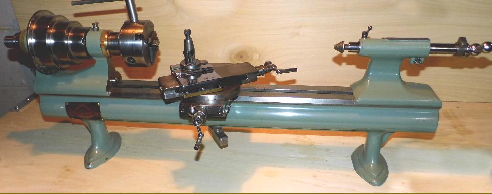
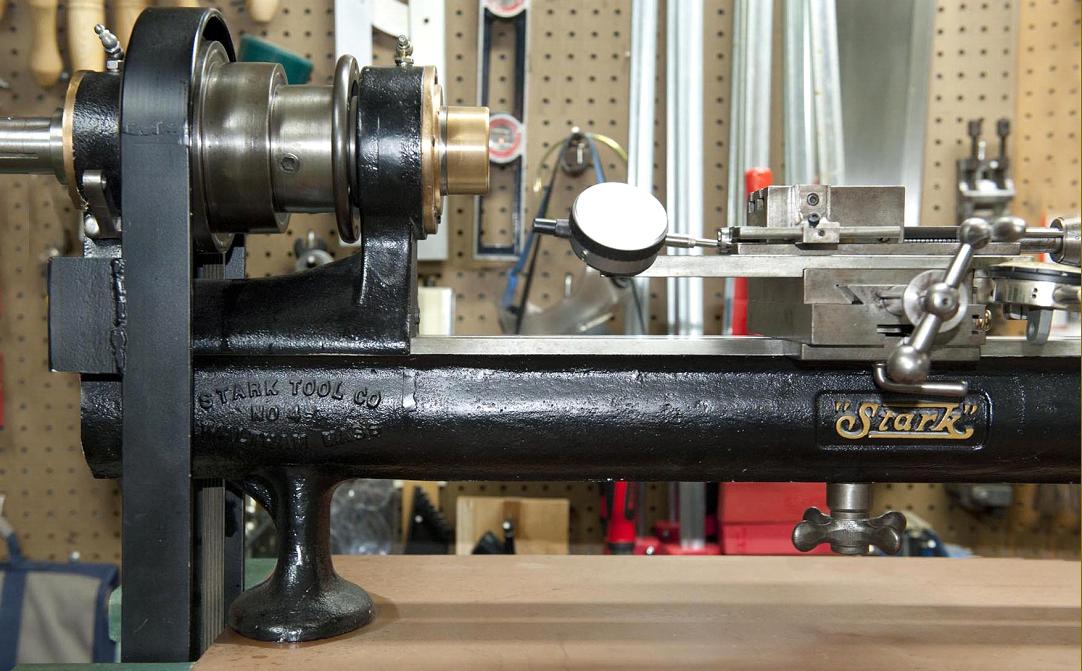
Stark No. 4 lathe with a plain-bearing headstock and complete with a compound screw-feed slide rest, cut-off (sometimes known as a forming-slide) and a lever-action headstock collet closer
A restored Stark No. 4 The 3-jaw chuck fitted is marked: SWEETLAND CHUCK #6 HOGGSON & PETTIO NEW HAVEN CONN
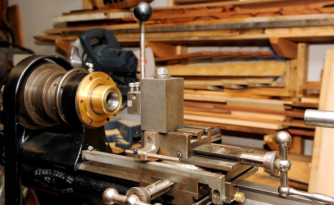
Cut-off and forming slide
Lever-operated cut-off (sometimes called a forming-slide) used when the lathe was set up for production work
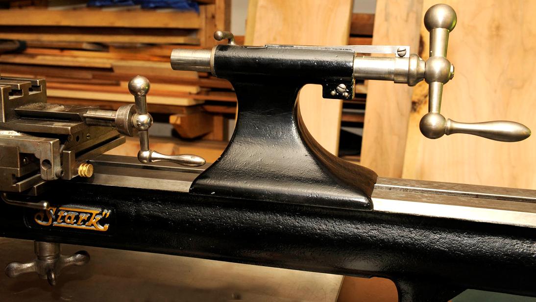
Light-pattern lever-feed tailstock
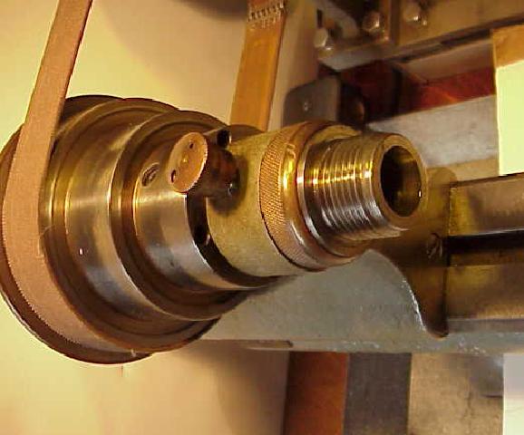
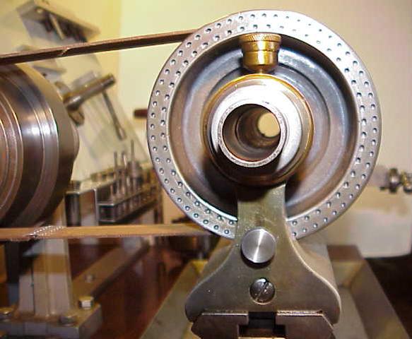
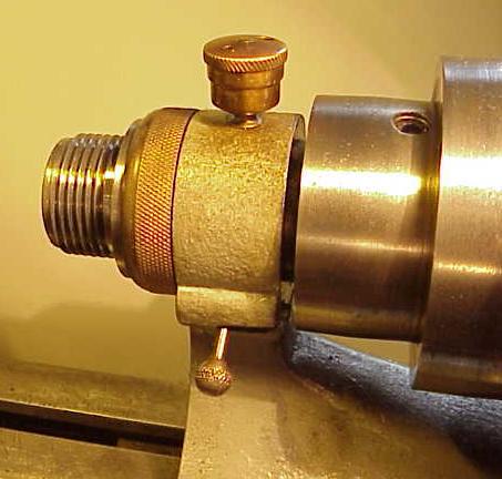
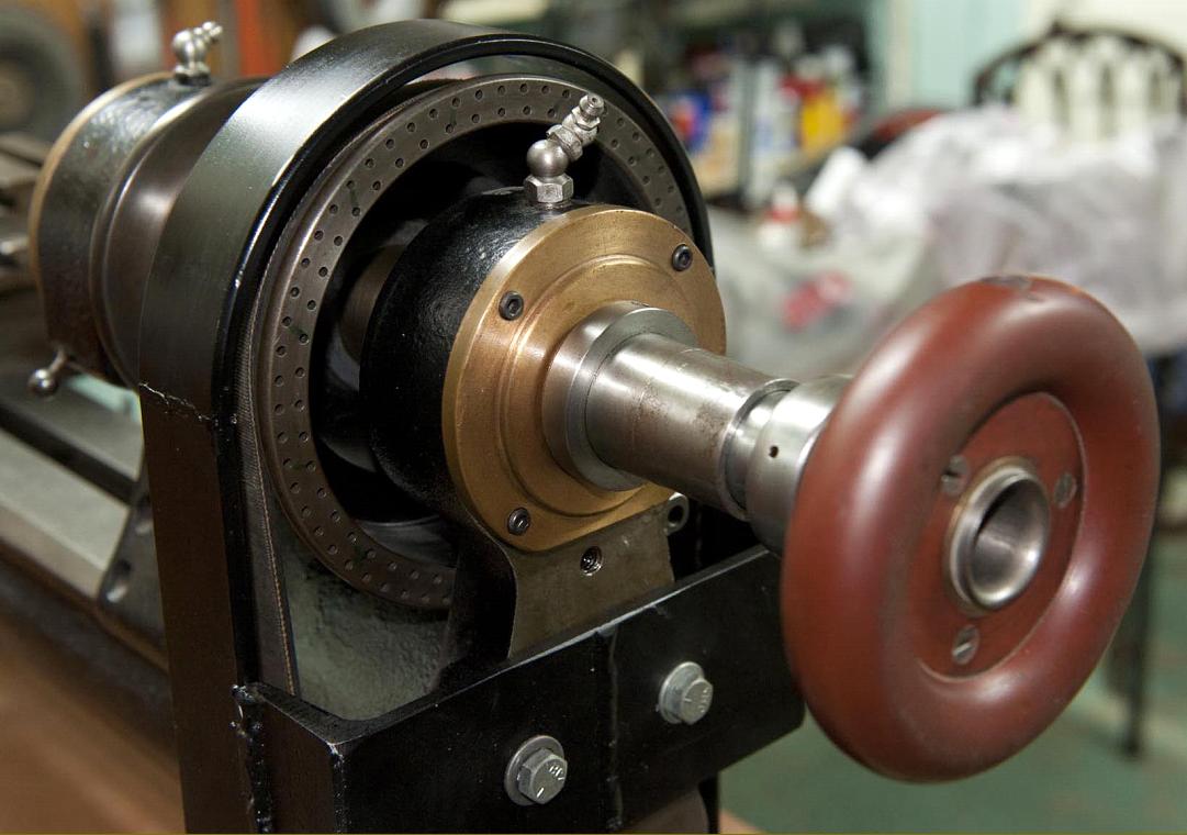
An essential accessory for production work the lever-action collet closer could be provided for all models of Stark Precision bench lathes
Standard screw-feed tailstock
Compound slide rest with a finely-engraved, bevelled-edged rotation scales both top slide and feed screws
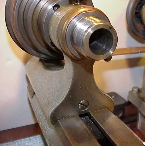
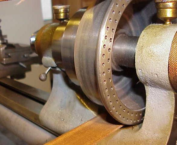
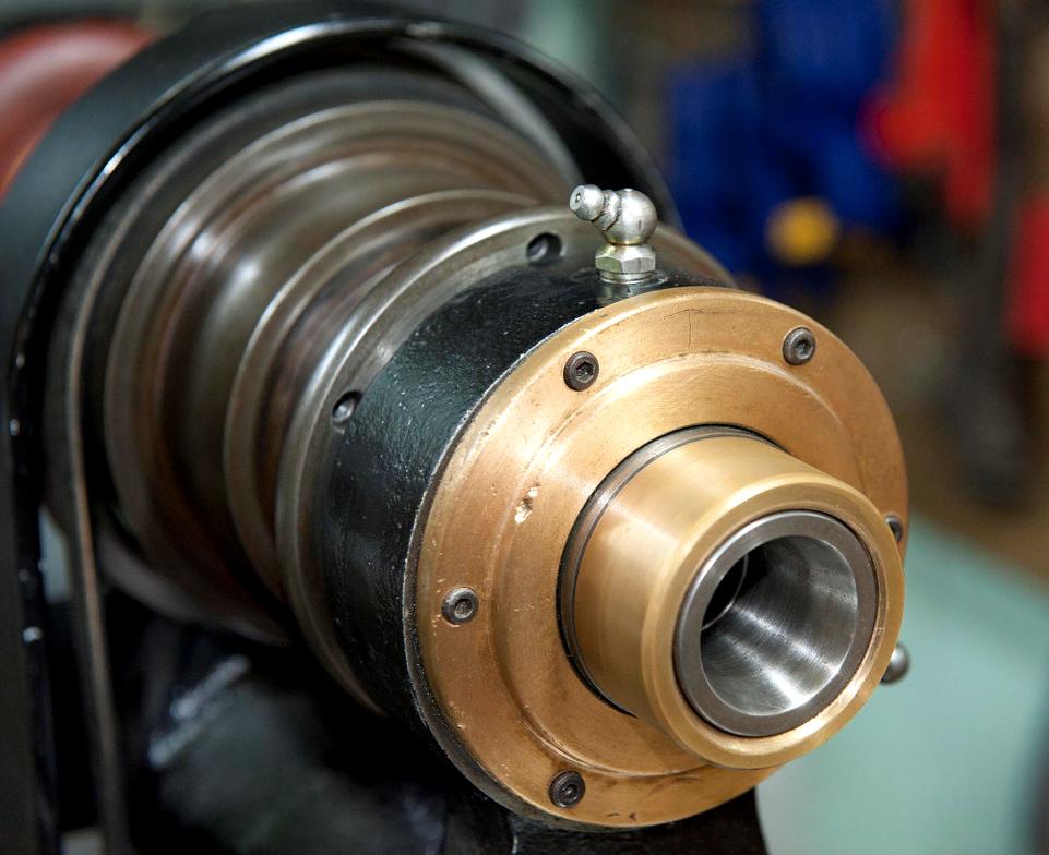
Plain bearing headstock
A Stark No. 4 lathe of the late 1920s to mid 1930 when the option became available of high-precision ball races in the headstock
A Stark No.4 that has survived with a remarkable number of original accessories including a 6-station,
bed-mounted capstan unit, fixed steady, a full set of collets and the correct countershaft unit,