|
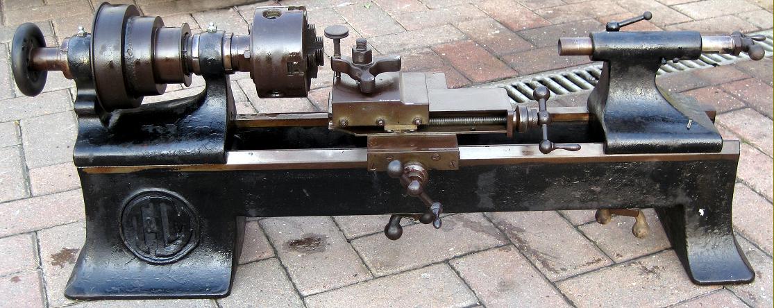
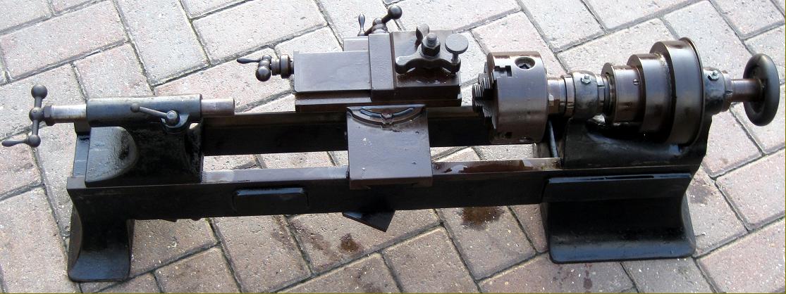
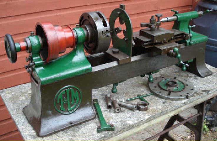
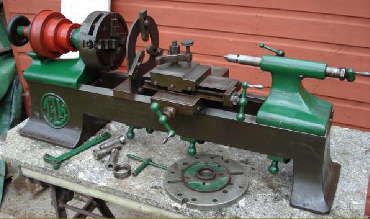
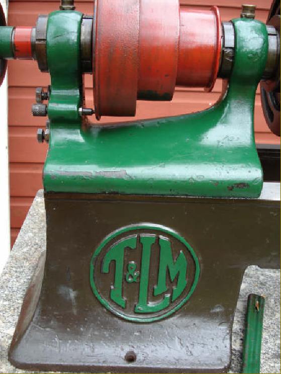
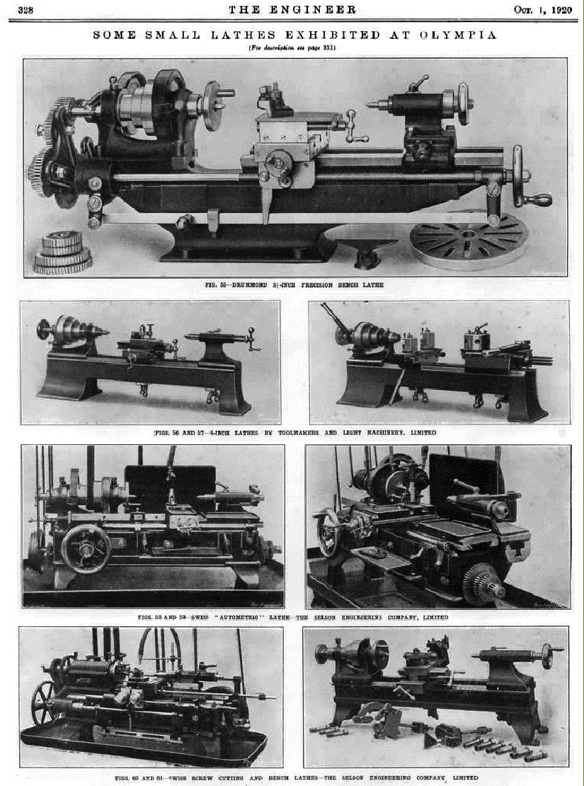
Another long-forgotten precision bench lathe designed for instrument, tool-room and "light manufacturing" the 4-inch centre height by 14-inches between-centres T. & L.M. was manufactured by Tool Makers and Light Machinery Ltd. at their factory in Lower Oxgate Lane, Cricklewood, London. With no creditable UK-based manufacturer of precision bench lathes, it was almost certainly made from the outbreak of WW1 in 1914 until the early 1920s (an advertisement survives from 1920), at a time when the usual German lathes by the likes of Lorch and G. Boley were, of course, unavailable. Adverts for the machine continued into the 1920s, the lathe at one time being marketed by Charles Churchill who advertised it alongside another bench precision lathe, the "Carson".
Using only conventional machine tools, the firm managed to produce a creditable product with an article carried by Machinery Magazine revealing some of the special techniques used to manufacture a lathe of this class. T & L.M. also made a small horizontal milling machine - but these even rarer than the lathe and the writer has only seen one.
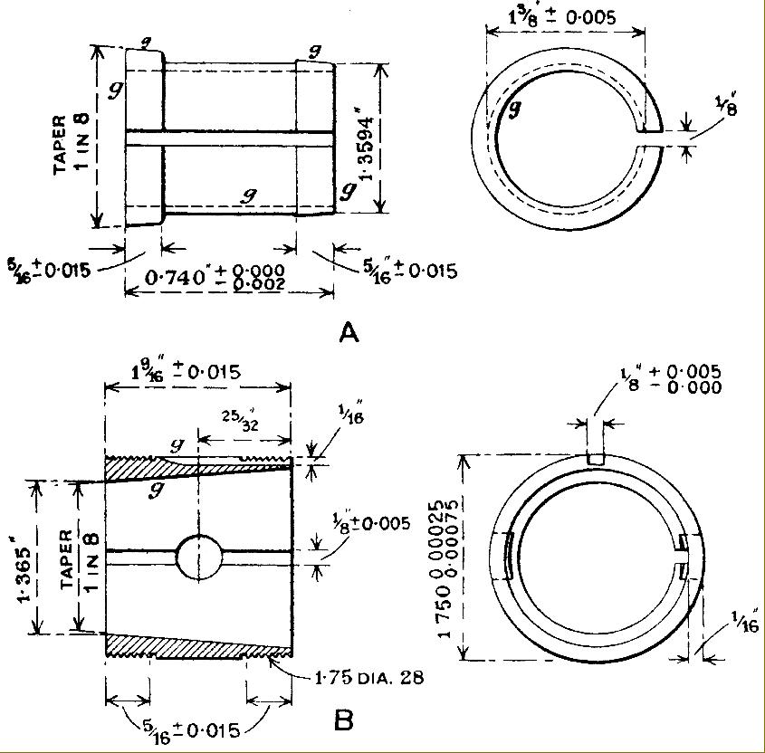
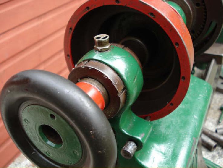
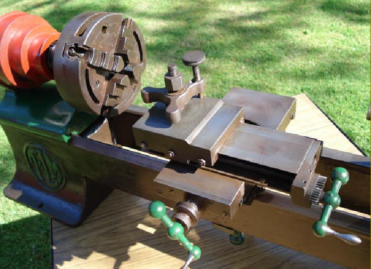
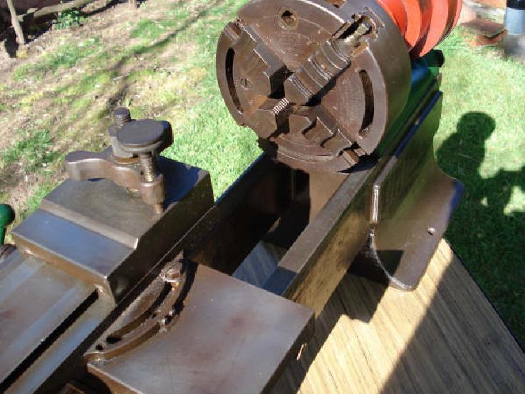
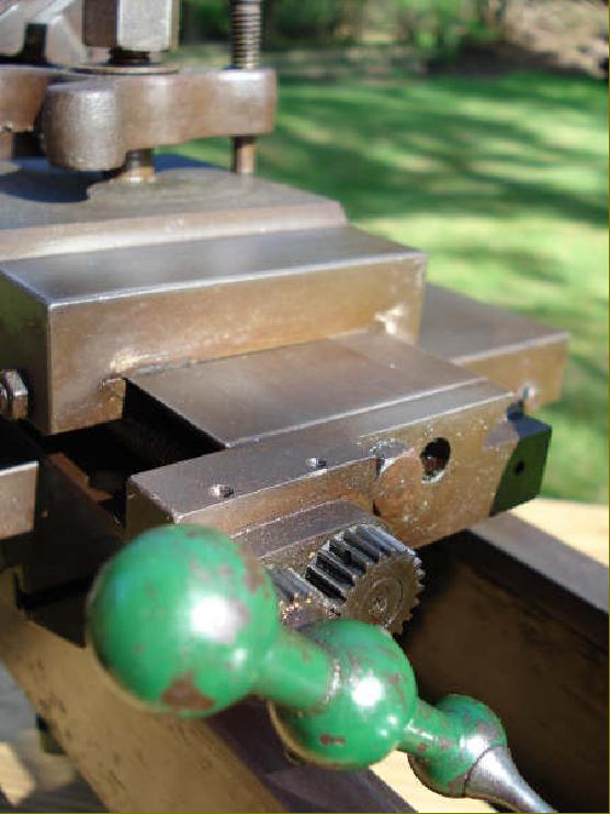
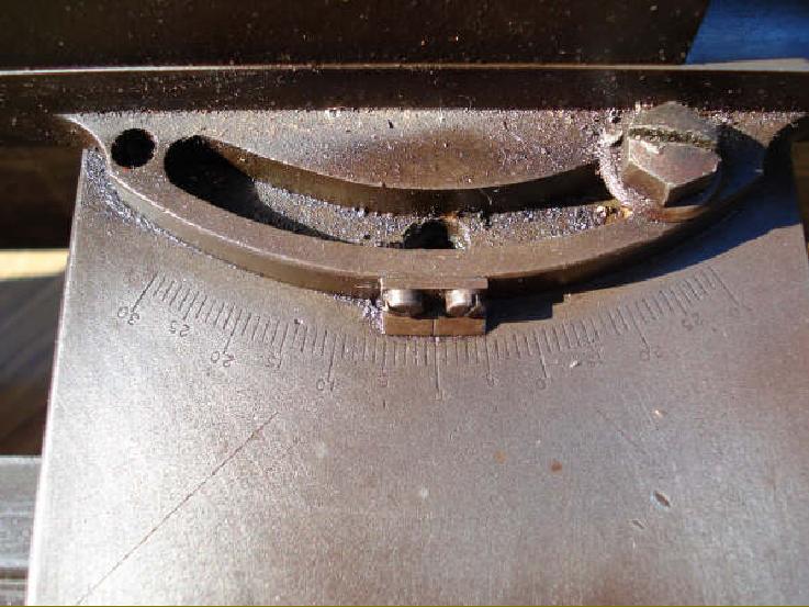
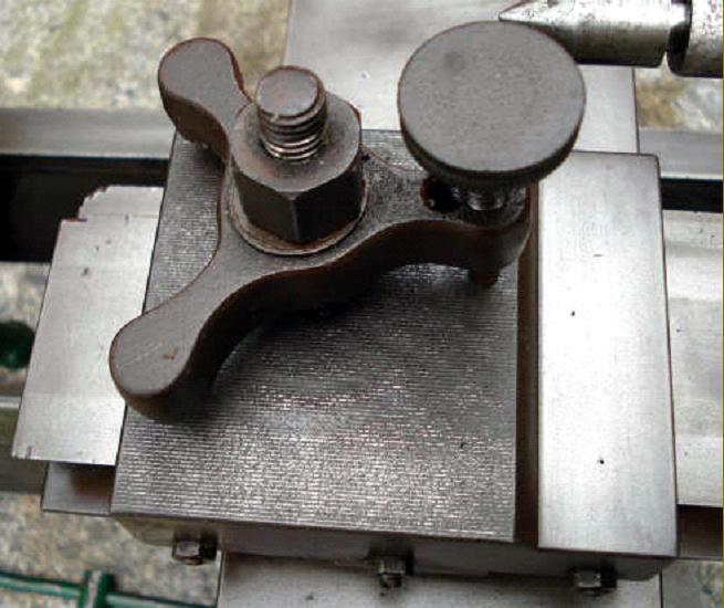
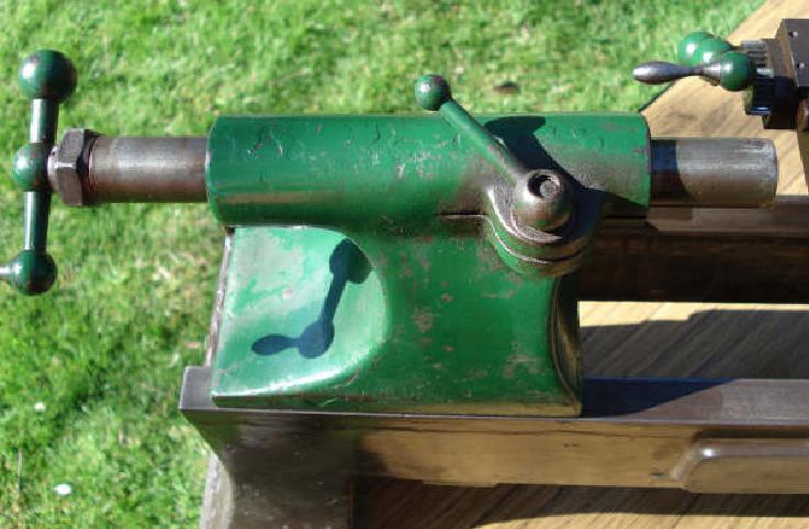
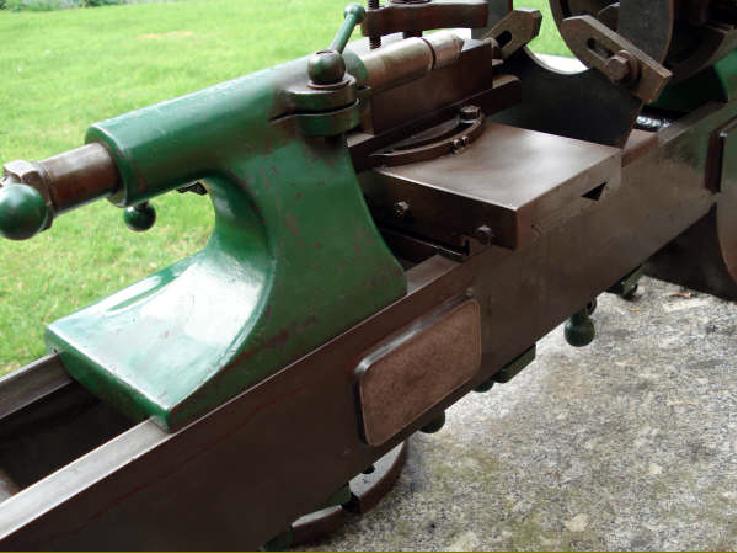
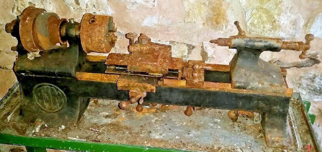
With a bed having a large V-way at the front and a flat at the rear the elegance of design, usually so prominent in this class of miniature machine, was spoiled by a rather clumsy treatment of the cast-in bed feet. However, this was no doubt compensated for by the unusually long foot at the headstock end adding stiffness to the assembly. To ensure absolute accuracy of alignment, the base of the headstock was hand scraped to the bed. Having a generous 0.75-inch bore, the headstock spindle (which looks from the sectional drawing in the advertising literature to have had rather thin walls) was manufactured from case-hardened and ground "Ubas" steel and ran in parallel, split, hardened steel bearings (1.25" in diameter at the front and 1.1875 "at the rear) screwed into tapered sleeves that were threaded at each end to accept adjuster nuts. The spindle end float was adjusted out against the inside face of the front bearing and the thrust absorbed against a hardened ring at its left-hand end. The end bearing was free to move laterally, the idea being to allow some expansion of the spindle as it warmed in service. Although oil caps were fitted above each bearing, the lubricant did not flow straight into them; instead it was led into small sumps from where felt pads drew it upwards by capillary action to prevent the ingress of dirt and grit - slots being cut into the lower section of each bearing to allow room for the felts to rub against the spindle. Although the headstock pulley had its smallest diameter against the front bearing (in traditional precision bench lathe practice) only a very modest effort was made to increase the mass of metal surrounding the front bearing). The left-hand face of the largest pulley carried a single circle of 12 indexing holes (where several rings or at least one ring of 60 would have been more useful) with a hardened locating pin. However, the width of the flat belt, at 1.25 inches, was a little more generous than usual. With the recommended countershaft running at 500 r.p.m the lathe had spindle speeds of 170, 280, 460, 650, 900 and 1500 r.p.m. Supplied as part of the standard equipment, the compound slide rest clamped directly to the bed (in the usual way) and carried a long-travel top slide with, unfortunately, its screw both off-set to the left hand side and exposed to the unwelcome attentions of turnings and chips. For some reason - possibly to bring the top slide handle out of the way of the tailstock when it was drawn close to the headstock - the designer chose to drive the top-slide feed screw through a pair of equal-size gears. The slide could be swivelled 30° in either direction from central, carried a very Boley-like tool clamp and was fitted with adjustable stops at front and rear. Both feed screws carried small zeroing micrometer dials.
Some considerable effort was made to impart a good finish: the bedways and some minor parts were polished and the paint treated to several coats of filler, rubbed down between applications before the final coat of an oil-resting enamel.
|
|