|
Manuals Machine Tool Catalogues Belts Accessories Books A suitable Handbook and Parts Manual is available for the Sanches Blanes lathe Sanches Blanes Sheraton Smart & Brown Storebro UFP Boffelli & Finazzi Demco NSTC Select (Lin Huan) Parkanson South Bend 9-inch Home Page South Bend Home Page 9-inch Lathe Accessories An Unused 9-inch South Bend 9-inch Clones In the Factory Original 1934 9-inch Model 5 World War 2 Export Papers Taper-turning Unit |
||
|
Sometimes found carrying a label stating: Craftsman fabricado pars a Sear, Roebuck SA, the Sanches Blanes version of the South Bend 9-inch was made in Brazil by "Industria de Maquinas Ferramentas. Ribeiraopires SP Industria Brasileira". The lathe was made in the usual South Bend configurations of A, B and C models with, respectively, a screwcutting gearbox and power cross feed; changewheels and power cross feed and changewheels and hand-powered cross feed. While early examples may have faithfully followed the original South Bend design, later models of the 117 mm (4.6") centre height by 600 mm (23.6") between-centres lathe had major modifications: the 3-step headstock pulley appears to have been made exclusively as a V-belt type and the backgear assembly used expensive helical gears - quieter and smoother running than the original type (and able to absorb greater loads) with taper roller bearings used to help cope with the additional end thrust that this type of installation usually generates. With a 50 Hz motor spindle speeds were: 75, 115, 190, 395, 620 and 990 rpm and with a 60 Hz unit: 90, 140, 230, 480, 750 and 1200 rpm. To help the operator (and never found on any South Bend example), micrometer dials were fitted to the tailstock spindle and the carriage handwheel (though unlike the Boxford copy and other clones, Sanches Blanes appear not to have taken the opportunity of enlarging the dials on the cross and top slide screws, these remaining at inadequate small diameter as used on South Bend lathes from the 1930s). One major alteration concerns the apron on late-model machines, this appearing to have been considerably beefed-up with the possibility that the power-feed mechanism was also altered. |
|
Catalogue picture of a Sanches Blanes Model C with screwcutting by changewheels and hand cross feed. The bed feet resemble those fitted to South bend lathes of the late 1940s and early 1950s. The micrometer dials appear to be just slightly larger than those of the parent machine. |
||
|
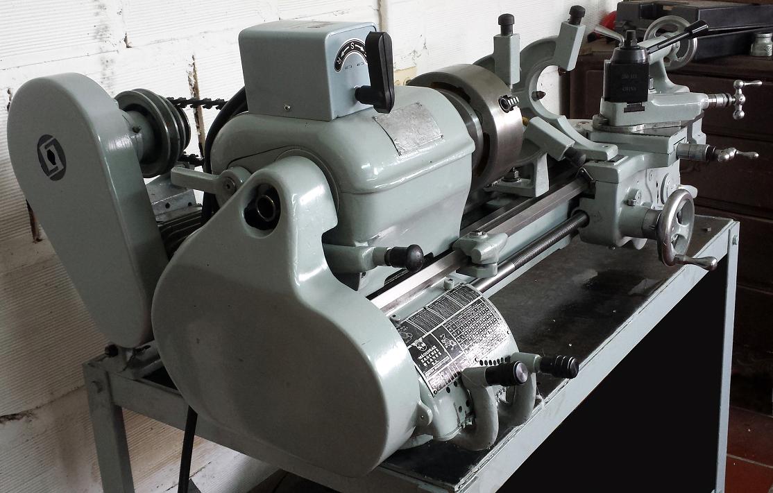
Rather than a V belt running from a V pulley on the motor to a narrow flat belt on the countershaft (as on the USA version) that on the Sanches Blanes used two V pulleys. |
||
|
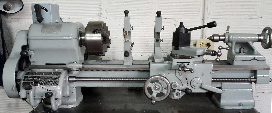
A later "Model TMB230 " Sanches Blanes (in effect a Model A South bend) with screwcutting gearbox and power cross feed. Although a standard South Bend type swing-open changewheel guard was fitted the headstock belt was guarded by a proper hinged cover. The tumble reverse lever used, like the Boxford and some other clones, a quick-action, spring-loaded selector instead of the slow-to-use South Bend original that required a bolt to be slackened and retightened when the setting was changed. |
|
The disposition of the indents holes shows this lathe to have a gearbox set to cut inch-pitch threads. Note the capstan drive for the tailstock barrel (a rare but useful fitting) and the oversize thread dial indicator. It is not known if the graduated handle fitted to end of the leadscrew is home-made or official accessory. |
||
|
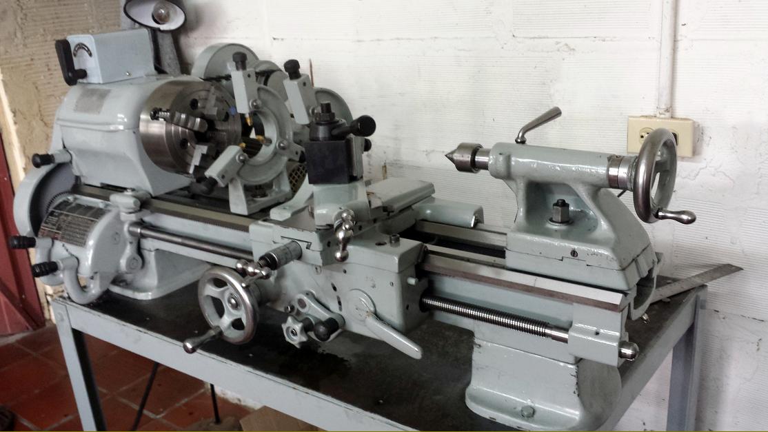
Model A Sanches Blanes with taper turning. This lathe exhibits small detail differences to the models above showing that sales must have been good enough to encourage a programme of development. |
|
|
|
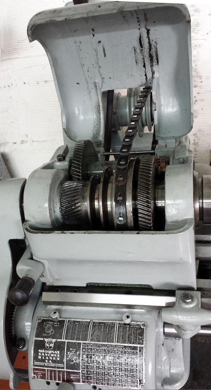
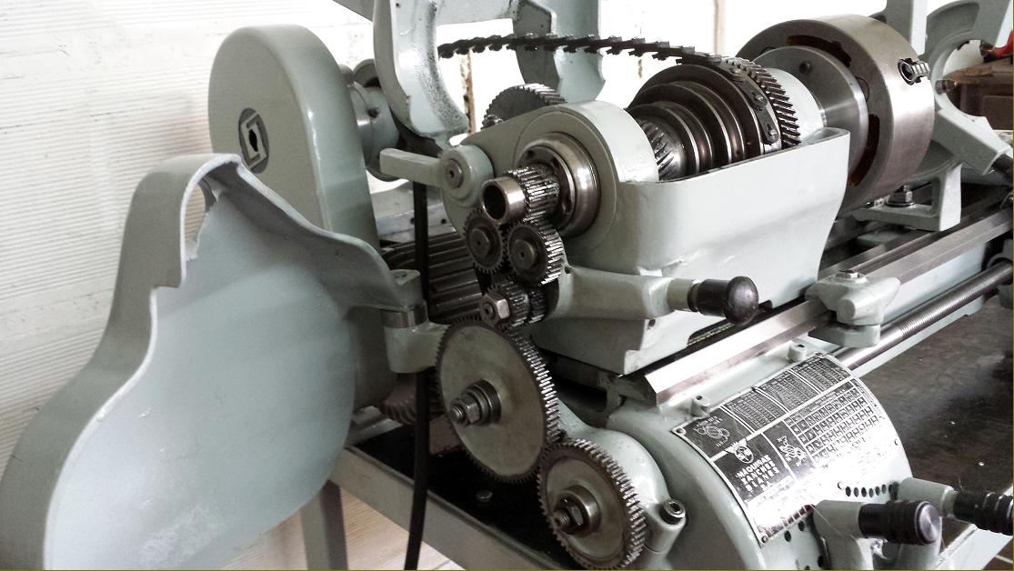
Timken taper roller bearing headstock with (expensive) helical backgears. The helical backgears would have been quieter and smoother running than the original (spur) type and the taper roller bearings would have helped to cope with the additional end thrust that an installations of this type usually generates |
||
|
|
||
|
|
|
Ace Blomqvist Boxford Hercus Joinville Moody Purcell An Unused 9-inch South Bend 9-inch Clones In the Factory Original 1934 9-inch Model 5 World War 2 Export Papers Taper-turning Unit the Sanches Blanes lathe E-Mail Tony@lathes.co.uk Manuals Machine Tool Catalogues Belts Accessories Books |
||