 |
|
|
|
|
|
|
|
|
|
|
|
|
|
|
|
|
|
|
|
|
|
|
|
|
|
|
|
|
|
|
|
|
|
|
|
|
|
|
|
|
|
|
email: tony@lathes.co.uk
Home Machine Tool Archive Machine-tools Sale & Wanted
Machine Tool Manuals Catalogues Belts Books Accessories
Colchester Student & Master Mk. 1 & Mk. 2 Lathes
& Colchester Dominion Lathes Page 1
Clausing 12" and 13" Models 6564, 6565, 6524, 6525, 6566,
6567, 6526, 6527, 8010, 8011, 8012, 8013
High quality andbooks & Parts Manuals are available for the Mk. 1 & Mk. 2 Models
**************************************
Colchester Home Page
Colchester Small Lathes 1908-1930 Colchester 1919 Colchester 1920s Mascot 1914-18
Master & Triumph 1930s to Early 1950s Master-1940s/1950s Photo Essay
Bantam 1920/30s Bantam & Colt 800,1600 & 2000 Chipmaster Student Mk. 1 & Mk. 2 & "Dominion"
Master Mk. 1 & Mk. 2 Master 2500 Student 1800 Student 3100 Triumph Mk. 1 & Mk. 2 Triumph 2000
Mascot 1950s Mascot 1600 Mascot 1914-18 Mastiff 1400 Magnum
Serial Numbers Factory Tour Quality Testing Colchester Catalogue Covers Early Drive System
Triumph VS2500 Mascot VS2000 Mastiff VS1800
|
|
|
|
|
|
|
|
|
|
|
|
|
|
|
|
|
|
|
|
|
|
|
|
|
|
|
|
|
|
|
|
|
|
|
|
|
|
|
|
|
|
|
|
|
|
|
|
|
|
|
|
|
|
Founded in 1908 - when they made a Drummond-like 3.5-inch lathe - by the early 1950s Colchester products were beginning to look distinctly old-fashioned, indeed, hardly any different from their pre-WW2 counterparts. To remedy the situation the Company began the introduction, one by one, of new versions of their long-established 6.5-inch Master and 7.5-inch Triumph models (and an improved but still awkward-looking 8-inch Mascot) together with one additional and important newcomer (and the first in the series), the 6-inch Student. Backed by redesigned and part-colour advertising literature, the new lathes were all styled to closely resemble each other and employed a common and easily used control system that allowed apprentices and regular operators to move quickly and safely from one model to another. Following contemporary practice they were mounted on neat, self-contained cabinet stands with a built-in electrical system, storage drawers (with a lock that also isolated the motor) and provision for an internally mounted coolant tank and pump. Although the model names may have been old these new machines represented a quantum advance for the firm and were assembled in what was to become Europe's largest plant devoted to the manufacture of lathes. Two 300-foot long moving-floors were used, together with a system of "flow-line" production based on automotive practice that aimed to achieve a consistently high standard of quality to "American toolroom limits of accuracy". However, like all production processes, and despite the new factory and much fresh equipment, hidden factors contrived to make some lathes more accurate than others, a fact that the Company turned to advantage by choosing the best machines from each production batch and offering them (with black micrometer dials) as machines to improved "toolroom" standards of accuracy. As was often the case with Colchester lathes, a copy of the Mk.1 was made in Taiwan and branded B.I.E. (and possibly with other names) and sold in the USA with its apron having the carriage handwheel to the left rather than on the right.
Although the new models shared many design clues with earlier versions, and had very similar-looking geared headstocks and apron controls, there were few interchangeable parts (or accessories), showing that each had been newly and individually designed for a particular class of work. The success of this engineering and marketing strategy was particularly evident in the case of the Student and Master for the two models were, over the next 20 years, to prove enormously popular in both training establishments and small professional workshops and to became by far the most popular and common mid-sized lathes on the British used market.
Ignoring the pre and just post-WW-2 versions (on their open distinctive and old-fashioned looking cast-iron legs) the three most common versions of the Student and Master likely to be encountered today are the early "round headstock" Mk. 1, the "flat-top headstock" Mk. 2 and the more modern "1800/2000/2500" series; these notes concern only the Mk.1 and Mk. 2. The Triumph was produced in only a single form during the 1950s and early 1960s (though the apron was changed for a single-lever safety type) before becoming the very different (and highly successful) Triumph 2000. Although the basic design of the Triumph and its controls closely mirrored those of the smaller machines (and much of what follows is also applicable to that model) a separate section has been devoted to this machine to outline differences in screwcutting and other capabilities.
The names "Student" and "Master" (of both the Mk. 1 and Mk. 2 designations) refer, in effect, to the centre height and bed length - the Student being 6" x 24" and the Master 6.5" x 36" - for, in all other respects, the lathes were identical (in reality, most Student lathes appear to have been built with a 6.5-inch centre height - so beware if buying a replacement tailstock). Although the specification laid down in the sales literature was quite unambiguous, the factory would build a batch of machines with any modifications (or mixture of features) that the customer desired and the author has seen, over the years, examples that combine almost as many changes and adaptations to the previous differences as could be imagined. The factory even offered "special single or two-tone colour finishes" and the option of chromium-plated control levers and handwheels. However, one unvarying feature was that, on gap-bed lathes, the carriage-traverse handwheel was positioned on the right-hand side of the apron and on straight-bed machines it was always to the left.
Beds
The bed on all models was braced by heavy elliptical cross-ribbing, the ways were ground finished and, at extra cost, could be induction hardened (in which case the machine carried a small sticker at the tailstock end proclaiming the fact). Both straight and gap beds were listed and, although a very useful feature, the latter can suffer one or two problems: if the gap is removed for a large-diameter turning job and not immediately replaced for ordinary turning, the bed (especially on unhardened models) will suffer excessive wear as the saddle is unsupported when the turning tool reaches the chuck-end of the workpiece. When replaced, the gap can cause inaccuracies as the saddle runs over it; the cause is usually dirt between the mating surfaces or uneven tightening. Before refitting make sure that the whole of the gap section is scrupulously clean, insert the screws, bring the saddle over the piece to roughly align it then lightly tighten the screws a little at a time. Final alignment can be made with a few blows in the right direction from a hide-faced mallet before tightening the four Allen screws fully and evenly. One tip is to strike the lathe bed near the gap (rather than the gap piece itself) to help bed things in. When removed, always store the gap piece in the lathe cabinet - or it will certainly be lost.
Continued below:
|
|
|
|
|
|
|
|
|
|
|
|
|
|
|
|
 |
|
|
|
|
|
|
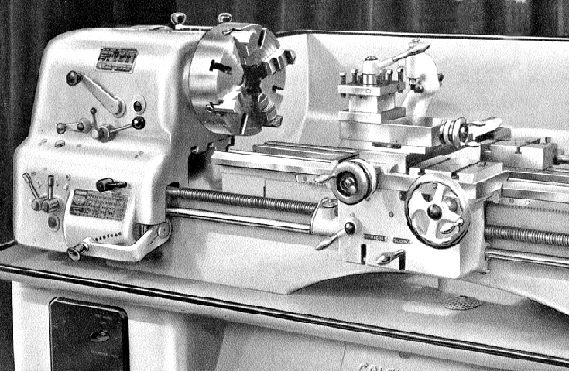
Round-top headstock Colchester Student & Master Mk. 1 (see below for the flat-top headstock Mk. 2)
Continued:
Drive System and Spindle Speeds
Although the option of fitting the Master (but not Student) to old-fashioned cast-iron plinths (and rigged for drive to overhead line shafts) remained for a few seconds and check that the belts are still in line; it's almost certain that they will not. Should it prove impossible to buy a pair of genuine "matched" belts, either buy a dozen standard ones (and find the two closest in length) or, even better, use a modern T-link belts. A further point on V-belt drives (and relevant to all applications) is the effect of belts with sections worn thin: as the worn sections fall into the pulleys and the thicker sections ride up them this effectively varies the gear ratio and causes the drive to speed up and slow down. The end result is vibration, with detrimental effects on the longevity of the machine and often a poor surface finish on workpieces. Fitting new V-belts can often make a significant different to how smoothly a machine tool runs.
The range of spindle speeds differed slightly according to the year of manufacture. Machines produced immediately prior to the 1950s Student and Master usually had a rather slow range, from 20 to 550 r.p.m., with the new models much faster at 52 to 1000 r.p.m. and later further improved to 54 -1200 r.p.m., both with eight speeds. Two-speed motors were a costly and hence infrequently fitted option, but gave sixteen speeds from 34 to 1500 rpm or even, on some very rare, special-order models, 17 to 750 rpm.Another (rarely-encountered drive configuration) drive used a two-speed Brook Compton motor and an electrically-actuated disc brake. On this model the normal "plug-in" electrical control panel on the front of the stand was replaced by a line of four switches and a stop button immediately beneath the front edge of the chip tray. This version also had a "third-shaft" control rod fitted below the powershaft and operated by a lever attached to the right-hand end of the apron - an arrangement not unlike that employed on a Mk. 1 Bantam. At the right-hand end of the rod was a box, containing a cam that operated the special Klockner Moeller reversing switchgear. On some of the Klockner-equipped lathes an unusual (and presumably heavier-duty) main spindle arrangement has been found where, instead of the components being located by a single key a much heavier fully splined shaft was used with the sliding components engaged by dog clutches. If you have one of these models the writer would be interested to hear about it.
As standard, both Student and Master were fitted with a spindle brake, operated by a horizontal lever (on the headstock's front face) that also acted as a motor switch. To start the lathe the lever had first to be pulled out against a safety spring (designed to prevent accidental engagement then lifted up (this mechanism was later more fully developed with a proper external gate and called "Safti-lok" by the makers). The lathe was stopped by returning the lever to its central position and then pressed down further to operate what was, when the lathe was new, a powerful drum brake built into the headstock input pulley - though Colchester's assertion that this stopped the spindle "instantaneously" revealed that the handbook writer had either not used the lathe - or a dictionary. However, the brake was very useful, especially to those being paid on "piece-work" who would otherwise have had to watch the seconds tick away as 120 lbs of cast iron came slowly to rest from top speed. It's worth knowing that, after many years of neglect, the headstock brake first becomes ineffective and then (usually following ham-fisted attempts to improve it) may start to interfere with the free running of the spindle. If your Colchester shows signs of slowing down or even "seizing up" after a few minutes running, the brake assembly is the first place to look. If shoe linings are badly worn most industrial areas have a friction-materials specialist who can bond on new material. Unfortunately, unlike the competitor English Harrison lathes, a combined clutch and brake was not fitted as standard but a multi-plate clutch manufactured by "Matrix" used instead. This was a very well designed, easily adjusted and reliable device - and one that should still be working perfectly when any lathe fitted with it is otherwise worn out. Although a 3-phase motor is very robust, and will put up with a good deal of abuse, its 1-phase cousin is a relatively delicate thing and best run near its rated capacity all the time (i.e. worked nearly flat out); if such a motor is switched on and off frequently against "no load" the windings will be damaged and, if run through a cycle where it is started, worked briefly, stopped and started again, the capacitor will fail prematurely. To prevent this happening on 1-phase (and DC) equipped lathes Colchester fitted a Matrix clutch as standard - even though it meant sacrificing the benefits of a brake. On clutch-equipped lathes the stop/start handle was adapted to open and close the plates with a separate electrical switch on the front control panel. In normal use, once started, the motor was left running for as long as possible, the spindle being controlled by the clutch. If you come across one it is worth knowing that on early clutch-equipped lathes the safety-spring loading on the start handle was not fitted - and accidentally brushing against it can start the lathe running. If needed, a clutch can be retrofitted to a used machine - but make sure you acquire all the operating linkages as well. An electrical reversing switch was (at first) an optional extra and, if chosen, was neatly built onto the hub of the stop/start lever and worked concentrically with it.
Continued below:
|
|
|
|
|
|
|
|
|
|
|
|
|
|
|
|
|
|
|
|
|
|
Continued:
Headstock
The 1.5" bore No. 3 Morse-taper headstock spindle (bushed down to No. 3 Morse from something close to, but not actually, a No. 5 Morse) carried an American Type L (long-taper) nose - this, for the benefit of readers unfamiliar with the world's first widely-adopted safety spindle fitting, consists of a large screwed ring (held captive on the spindle's tapered and keyed nose), with a matching thread taper in the chuck backplate. Unfortunately, the various sizes of this fitting are easily confused by the inexperienced; the Student and Master both used the L0 (L-zero) size, while larger models used an L1 or L2, (etc.) - and smaller machines the L00. If you have a sample with which to make ca omparison, all is well, but it is very easy to believe that the fitting either side of the one you need is correct. If you look carefully the size is (usually) stamped somewhere on the backplate; failing this - do your homework, and use a ruler. The 8-inch 3-jaw chucks commonly fitted to these lathes when new were high-quality ones, with an integral backplate, made by in the UK by Burnerd. Today these special chucks are no longer available, but new standard ones can be fitted to a separate backplate - however, don't be tempted to use a cheap, unbranded import; the stresses encountered on top speed when holding large job are considerable. Instead, you are welcome to email for details of quality replacements that we can recommend.
The forged, high-tensile steel 1.5-inch (38 mm) bore spindle ran in Gamet "One-micron Precision" bearings - Gamet being a separate company within the controlling 600 Group who also supplied many other machine-tool makers. A small pre-load was applied to the bearings by spring pressure - that immediately behind the spindle nose being a double-row type with a single-row at the rear. Gamet claimed that the "unique design ... ensures minimum temperature rise and accurate running of the spindle throughout the speed range"
All the gears were hardened and honed with the 8 spindle speeds changed by two levers on top of the headstock together another, for high and low speed ranges, on the front. Unfortunately the gears of the Mk. 1 were never entirely silent, even when new (though individual examples did vary widely with some even being relatively "quiet"), and a "noisy" headstock can almost be expected on these machines. The Mk. 2, with gears cut on newly-installed German machinery, were much better but even so, prolonged use inevitably leads to a noisy headstock - the worst offender usually being that speed immediately below the highest. In an attempt to quieten the headstock some owners have mistakenly resorted to using a thick oil instead of the thin hydraulic lubricant that should be used; the heavier oil will defeat the spiral oil-return grove (built into the bearing cover plate on the left-hand end of the spindle) and appear to be almost 'sucked out' as the machine runs. Small oil leaks from the headstock are almost a feature of these lathes and, providing the oil is kept topped up, should result in no harm; the time to worry is when the oil stops coming out - the reservoir will be empty. If the rest of the machine is serviceable, but the headstock gears are in very poor or damaged condition, it might be worth removing the headstock cover and arranging a V-belt drive direct to the middle or end of the spindle from a variable-speed, inverter-controlled 3-phase motor; although a crude solution this has been known to extract another decade's life from some machines. On Student and Master lathes the headstock pivots on a dowel, fitted to the back corner nearer the tailstock and can, as a consequence, be adjusted. At the left-hand end of the headstock, sitting between the bedways is a block with pointed-end Allen screws that can be used, by slackening one and tightening the other, to swing the headstock slightly. Before doing this the holding down bolts, which have a little clearance round their holes, should be slackened but not loosened completely. An accurate test bar will needed (it fits directly into the headstock spindle), together with a high-quality DTI used to assess the alignment. Alternatively, test cuts can be taken between minute amounts of adjustment with the holding-down bolts fully tightened, of course.
Continued below:
|
|
|
|
|
|
|
|
 |
|
|
|
|
|
|
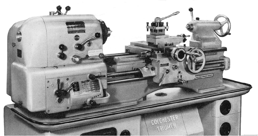
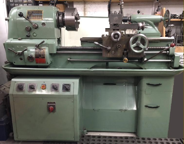
Colchester Student & Master/Clausing Mk. 2 with its angular styling
|
|
|
|
|
|
|
|
 |
|
|
|
|
|
|
|
|
|
A "Mark-one-and-a-half" Colchester Triumph/Clausing 15-inch (the Student, Master and Clausing 13-inch were laid out in an identical fashion) with the same style of rounded headstock but fitted with the improved design of "Safety" apron shared with the Student and Master models.
|
|
|
|
|
|
|
|
|
|
|
|
|
|
|
|
|
Continued from this page:
Screwcutting and Power Feeds
Both Student and Master were available with either screwcutting by changewheels or (and by far the most common specification) a dual inch/metric screwcutting gearbox. However, detailed differences in the screwcutting were noticeable over the years, with the first Student models listed with either a gap or straight bed and with either changewheel or screwcutting gearboxes in inch or dual inch/metric versions. The range was arranged as follows: "Cub", "Penny", "Colt" and "Dime" The Cub was a gap-bed lathe with screwcutting by changewheels (and a 2-speed gear on the leadscrew); the Penny (later called the Dominion) was a straight-bed model also with changewheels; the Colt had a gap bed and a dual inch/metric quick-change screwcutting gearbox with 36 inch pitches from 4 to 60 t.p.i. and 11 metric from 0.5 to 6 mm. A special feedbox was available for the Colt (at extra cost) that had no metric capability and incorporated pitches of 5.75, 11.5, 23, and 46 threads per inch, but at the expense of omitting the 7.5 15, 30 and 60 pitches. The Dime was another straight-bed lathe with a screwcutting gearbox having 36 inch pitches - though at extra cost the dual metric/inch box from the Colt could also be fitted.
Later versions of the Student, and all models of the Triumph, had screwcutting gearboxes able to generate 45-inch pitches from 4 to 120 t.p.i. and sliding 45 feeds from 0.0025" to 0.068" with cross feeds set at exactly one-quarter those rates. 12 metric pitches could also be obtained (by just lifting a small lever on the face of the gearbox) of 0.25 to 6 mm pitch - though 14 pitches if you include 3·75 and 7·50 .
Just to confuse matters, the straight-bed, plain saddle model was also known as the "Dominion" and was listed in some catalogues as either a 6" x 24" or 6.5" x 36" model (some catalogues used the American system and called them 12"). At extra cost it could be fitted the dual inch/metric gearbox it was fitted as standard with either changewheels or an English-only screwcutting gearbox with two extra pitches of 11.5 and 23 t.p.i. By the mid 1960s a rare "Continental" all-metric model was also listed, a machine easily recognised by a distinctly different gearbox fitted with a Bantam-like joy-stick control lever on its front face. Both the Dominion and Continental boxes could be persuaded (at some expense) to generate metric and English threads respectively by means of translation changewheels.
Unlike their Harrison competitors, the changewheel models had no convenient and easily-operated 3-speed gearbox to allow a quick change in the rate of power feeds, instead a double gear on the feed shaft could be slid by hand into one of two positions to pick up a single gear on the leadscrew - and so select either a fast or a slow rate of feed. The changewheels were guarded by a cast-aluminium cover secured, not by a hinge, but on studs; although this arrangement was perfectly satisfactory for use on the gearbox-equipped models on the changewheel version, where access to the gears was required for every change of thread, the design was a considerable inconvenience.
All Mk. 1 and Mk. 2 Students and Masters had a 6 t.p.i. leadscrew with no metric alternative save, possibly, for the Continental model. The latter, being an all-metric machine, produced metric threads without any extra expense - and came with a 127t transposing changewheel for imperial screwcutting and could also generate 'Module' pitches. The leadscrew was used only for thread cutting and not power feeds - normally it was left disengaged by positioning the inch/metric thread-selector handle in its middle position. However, the Power sliding and surfacing (along the bed and across) was provided by a separate power rod and fitted to all models with, on the Mk. 1, both selection and engagement by a single lever that was slid along the lower edge of the apron and lifted (and locked) into one of two slots. Releasing the feeds merely required the lever to be pressed downwards; unfortunately, the heavier the cutting load the greater the effort required to disengage it, but at least it was a positive in-out action and did not require (as on so many older lathes) a knob to be unscrewed to release a clutch.
The apron was double walled but open at the bottom, so precluding any chance of the gears being run in oil and requiring the operator to periodically supply lubricant. Unfortunately, in many cases, this simple task was ignored and allowed such severe wear to take place on the inside of the worm-wheel carrier that the whole assembly dropped so low that engagement became impossible.
A few Mk. 1 lathes had a ball-bearing "clutch" incorporated in the feed-shaft to protect the apron against overload damage - a mechanism that could be used to advantage in combination with bed stops to provide a reliable, automatic means of turning repeated shoulder lengths in production work. All models had a shear pin incorporated in the top gear of the screwcutting drive; when the leadscrew and power shaft refuse to rotate, this is the first place to look; if the pin has broken replace it with one made from aluminium, not steel. All versions were provided as standard with a thread-dial indicator built into a rather perfunctory cast-iron leadscrew guard.
Just before the introduction of the proper Mk. 2 the Mk. 1 was updated (as the jokingly-called "mark-one-and-a-half") with a completely redesigned and far safer apron. For the first time the bottom of the assembly was enclosed, allowing the gears to run in an oil bath, though oddly not all models had the sight-glass level indicator showing this feature was fitted. The function of selection and engagement of feeds was separated with a push-pull knob, protruding from the middle of the aprons face, selecting the feed and with engagement by flicking up and down a lever at the bottom of the apron - in the long-established Harrison manner. However, inside the apron the Colchester mechanism was quite different, and incorporated an important safety feature: an automatic feed knock-off for when cutting forces become too high. This was achieved by mounting the engagement mechanism on a separate carrier that transmitted drive to the carriage through a spring-loaded ball-bearing running up a ramp. To adjust the spring pressure (and so the release point) the engagement lever was given a threaded barrel (often found jammed tight) that the operator could screw in or out. By using a combination of a correctly-adjusted lever together with a bed stop a useful automatic-disengage could be set up by which means repeated runs could be made up to a shoulder.
Continued below:
|
|
|
|
|
|
|
|
|
|
|
|
|
|
|
|
|
|
|
|
|
|
Continued:
Saddle and Compound Slide Rest
On gap-bed lathes the saddle carried T-slotted wings (a "boring" saddle) and the straight-bed models wings with plain, ground tops; the main castings were all pre-drilled and tapped to accept such things as hydraulic-copying, taper-turning and other attachments but (surprisingly), until as late as 1959, felt bed wipers were an extra-cost option. The compound slide was entirely conventional, but well made, with stiff gib blocks screwed into the roof of the full-length cross slide with adjustment by screws through the sidewall. These side and top screws are time-consuming to adjust but, once set, the slide remains play-free for hundreds of hours. One potential weakness concerns the circular T-slot, machined into the cross slide, and on which the top slide rotates. The two T bolts securing the slide are small, and easily overlooked, but they must be kept tight for, if the cutting tool digs in heavily and the top slide is loose, the bolts may well smash the slot and wreck the (very expensive) slide.
Most lathes had either single inch or Metric zeroing micrometer dials but all could be fitted, at extra cost, with finely engraved dual inch-metric units each with a rather fragile cast-aluminium sliding cover. Both inch and metric feed screws and nuts were fitted, the type used on a particular lathe being denoted by the graduations of the outer ring. The cross-feed nut was adjustable to reduce backlash and it appears that both early and late types were used. The early was in three parts and held to the slide by a large exterior nut with an oil nipple in its centre; two of the nut's sections were threaded, with cotter pins passing through that engaged against a wedge to press them apart. The later version, which can be recognised by three Allen screws arranged in a line, was also in two parts but with the inner faces formed at an angle with a wedge between them. With the front screw fixed, that at the back could be slackened to allow the middle screw to be tightened onto the wedge and the two halves moved slightly apart and backlash eliminated.
Tailstock
The tailstock on early versions of the Student and Master had a barrel locked (by that pet hate of the writer) a slit in the casting closed down by the action of a screw thread. Fortunately, later machines were fitted with a barrel increased in size to take a No. 3 rather than the original No. 2 Morse taper and with a proper "split-clamp" that acted directly on the barrel at a point just before it emerged from the casting - a system that always works no matter how worn the components become. The bore of the casting was honed and the barrel (marked with both inch and mm graduations) ground to get as good a fit as possible and ensure a long and accurate life. The top of the unit could be offset on the sole plate for simple taper turning.
Student and Master Mk. 1 and Mk. 2 - Essential Differences
The most important differences between the Mk. 1 and Mk. 2 machines, apart from the apron, are found in the headstock where new German-manufactured gear-cutting machinery allowed the use of much quieter and smoother running gears. The obvious recognition points of a Mk. 2 are its angular styling and distinctive, flat, ribbed, aluminium headstock cover - a handy place to hold spanners, tools and small jobs in progress. Another safety feature of the MK. 2 was the "gate" on the high-low speed selector handle on the front face of the headstock. Before the lever could be moved it had to be pulled out and could not be accidentally knocked into neutral.
There was also an interim model (jokingly referred to as the "Mark one-and-a-half" with round headstock but the safety apron
The Student isuntil as late as 1960, the vast majority were mounted on the same type of full cabinet stand employed as standard for the Student. Both models are usually found with a 1425 r.p.m 3 h.p. 3-phase motor, though it's possible that some machines, sold to schools, might have been fitted with a 1.5 h.p. motor. Mounted on a large adjustable plate inside the headstock end of the stand, the motor pulley was arranged to take either a wide flat belt or double V-belts. Although efficient, the twin V-belt drive can cause problems and, should the geared headstock on any V-belt drive Colchester make a knocking, rattling or rumbling sound, the cause may not be worn gears or bearings but unequal-length drive belts "fighting" each other. To check, try running on one belt to see if the headstock runs more smoothly; if it does, fit a second belt, run a chalk line across the two, start the machine around 61 inches long, 30 inches wide and weighs approximately 1372 lbs. (625 kg). The Master is just one foot longer and weighs approximately 1400 lbs. (635 kg).
Clausing-Colchester
A version of the lathe was sold in the USA and Canada as the "Clausing-Colchester 13-inch" this lathe had an English-threads-only gearbox but a hardened bed as standard, straight or gap, with a choice of 24" or 36" inches between centres and, on the Mk. 2 versions, an improved version of the single-lever "Safety" apron that was modified to include an oil bath in its base..
|
|
|
|
|
|
|
|
|
|
|
|
|
|
|
|
|
|
|
|
|
 |
|
|
|
|
|
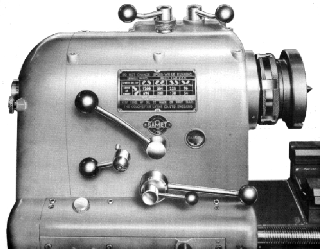
Mk 1 Student and Master Headstock
|
|
|
|
|
|
 |
|
|
|
|
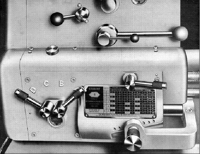
Mk 1 Student and Master screwcutting gearbox. Three versions were available: a dual English/Metric Box, a model labelled "Dominion 12" x 24", with English threads only and a very rare, all-metric version referred to as the "Continental" with both lever and joy-stick control; the latter box is shown below. To change from metric to English threads on the dual-box model required only that the operator altered the position of the horizontal lever immediately above the gearbox sliding selector.
|
|
|
|
|
|
|
|
|
|
|
|
|
|
|
 |
|
|
|
|
|
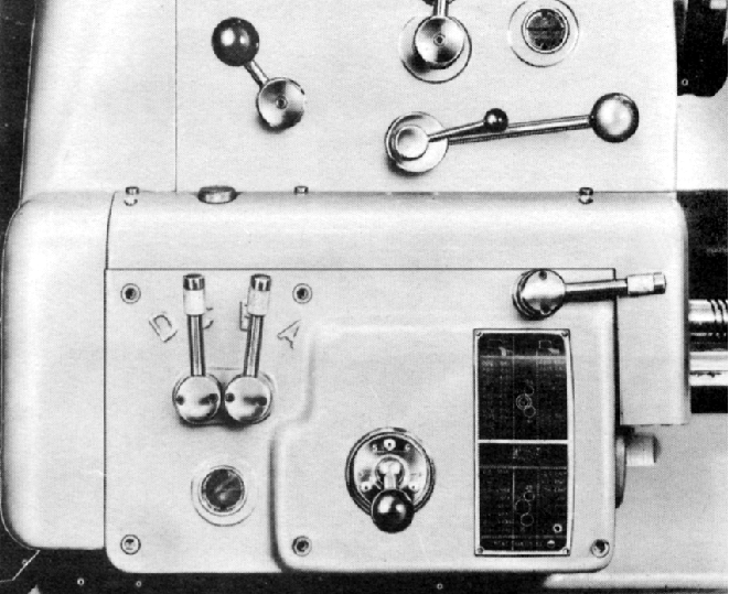
Rare all-metric screwcutting gearbox with its distinctive joy-stick control lever. This box required additional changewheels to generate a full range of threads.
The lever immediately above the screwcutting chart has two positions marked E and F. Moving the lever from one position to the other alters the leadscrew drive from 1 : 1 Ratio to a fractional ratio, with the last letter in the last column of the screwcutting charts indicating how the settings can be used. On the dual English/metric box the same horizontal lever was used to switch between the two thread types.
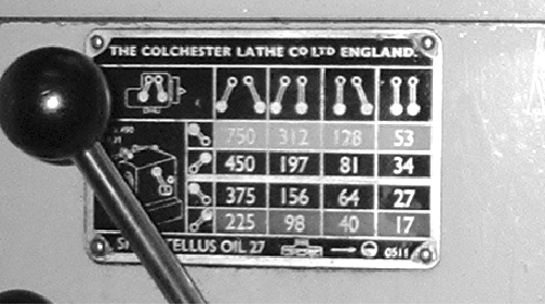
Screwcutting charts for this gearbox can be seen here.
|
|
|
|
|
|
|
|
|
|
|
|
|
|
 |
|
|
|
|
|
 |
|
|
|
|
 |
|
|
|
|
|
|
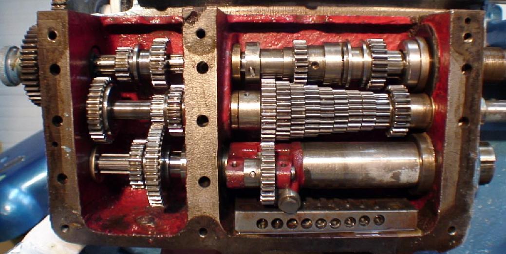
Inside the standard English/Metric screwcutting gearbox
|
|
|
|
|
|
|
|
|
|
|
|
|
|
 |
|
|
|
|
|
|
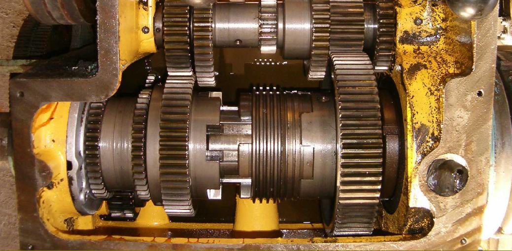
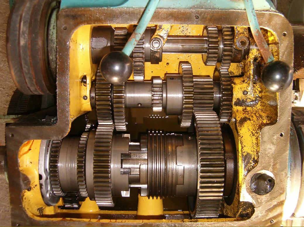
An unusual main spindle configuration found on a Mark 1.5 Student fitted with the rare Klockner Moeller reversing switchgear. On some of the Klockner-equipped lathes an unusual (and presumably heavier-duty) main spindle arrangement has been found where, instead of the components being located by a single key a much heavier fully splined shaft was used with the sliding components engaged by dog clutches. If you have one of these models the writer would be interested to hear about it. The ordinary main spindle had the main components held on a single key but this version uses a much heavier dog clutch arrangement. Below is the full arrangement of the headstock interior.
|
|
|
|
|
|
|
|
 |
|
|
|
|
|
|
|
|
|
|
|
 |
|
|
|
|
|
|
Student with the later single-lever "Safety Apron" and "Third-shaft" electrical control
Another drive used a two-speed Brook Compton motor and an electrically-actuated disc brake. On this model the normal "plug-in" electrical control panel on the front of the stand was replaced by a line of four switches and a stop button immediately beneath the front edge of the chip tray. This version also had a "third-shaft" control rod fitted below the powershaft and operated by a lever attached to the right-hand end of the apron - an arrangement not unlike that employed on a Mk. 1 Bantam. At the right-hand end of the rod was a box, containing a cam that operated the special Klockner Moeller reversing switchgear. On some of the Klockner-equipped lathes an unusual (and presumably heavier-duty) main spindle arrangement has been found where, instead of the components being located by a single key a was used with the sliding components engaged by dog clutches. If you have one of these models the writer would be interested to hear about it.
|
|
|
|
|
|
|
|
 |
|
|
|
|
|
|
Colchester Student with the rare splined main spindle. It is believed that
all these versions of this type had the heavy-duty Klockner Moeller switchgear
|
|
|
|
|
|
|
|
|
|
|
|
|
|
 |
|
|
|
|
|
Mk 1 Student and Master Apron - sliding feeds selector
|
|
|
|
|
|
 |
|
|
|
|
|
|
|
|
|
|
|
Mk 1 Student and Master Apron with the T-slotted saddle fitted to all gap-bed models
|
|
|
|
|
|
|
|
 |
|
|
|
|
|
|
|
|
|
Mk 1 Student and Master Apron with the plain saddle fitted to all straight-bed models
|
|
|
|
|
|
 |
|
|
|
|
|
|
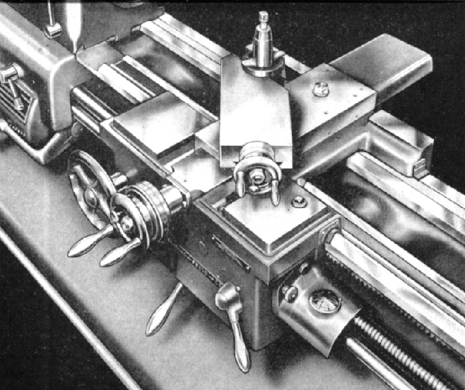
The "Safety Apron" had a single, centrally-positioned lever that could be screwed in and out to adjust the point at which the power feed released.
|
|
|
|
|
|
|
|
|
|
|
|
|
|
 |
|
|
|
|
|
|
Mk. 2 Student/Master with a special-order, low-speed
headstock driven by a two-speed motor.
|
|
|
|
|
|
|
|
|
|
|
|
|
|
|
|
|
|
High quality andbooks & Parts Manuals are available for the Mk. 1 & Mk. 2 Models
**************************************
Colchester Home Page
Colchester Small Lathes 1908-1930 Colchester 1919 Colchester 1920s Mascot 1914-18
Master & Triumph 1930s to Early 1950s Master-1940s/1950s Photo Essay
Bantam 1920/30s Bantam & Colt 800,1600 & 2000 Chipmaster Student Mk. 1 & Mk. 2 & "Dominion"
Master Mk. 1 & Mk. 2 Master 2500 Student 1800 Student 3100 Triumph Mk. 1 & Mk. 2 Triumph 2000
Mascot 1950s Mascot 1600 Mascot 1914-18 Mastiff 1400 Magnum
Serial Numbers Factory Tour Quality Testing Colchester Catalogue Covers Early Drive System
Triumph VS2500 Mascot VS2000 Mastiff VS1800
Colchester Student & Master Mk. 1 & Mk. 2 Lathes
& Colchester Dominion Lathes Page 1
Continued on Page 2 Page 3 Page 4 Page 5
Clausing 12" and 13" Models 6564, 6565, 6524, 6525, 6566,
6567, 6526, 6527, 8010, 8011, 8012, 8013
email: tony@lathes.co.uk
Home Machine Tool Archive Machine-tools Sale & Wanted
Machine Tool Manuals Catalogues Belts Books Accessories
|
|
|
|