 |
|
|
|
|
|
|
|
|
|
|
|
|
|
|
|
|
|
|
|
|
|
|
|
|
|
|
|
|
|
|
|
|
|
|
|
|
|
|
|
|
|
|
|
|
|
|
|
|
|
|
|
|
|
|
|
|
|
|
|
|
|
|
|
|
|
|
|
|
|
|
|
|
|
|
|
|
|
|
|
|
|
|
|
|
|
|
|
|
|
|
|
|
|
|
1902-1912 3.5" Small Lathes 1912-1921 3.5" Small Lathes
1921- 1924 3.5" Small Lathes 1925-1950s M-Type
Admiralty Power Cross Feed Lathe M-Type Photo Essay
M-Type Countershafts Lathe Headstock Comparison
Drummond 3.5-inch Parts Pictures Round Bed Drummond
Larger Drummond Lathes Drummond Lathe Accessories
The First Drummond Lathe First Series Production Drummond
Rare 4" Drummond Flat Bed Drummond Little Goliath
Serial Numbers Early Drummond Lathe Still in Use
Drummond Radial-arm Drill Geared-head Drummond
Walram Lathe Attachment Testing a Drummond Lathe
Drummond 5-inch Double-height Bed Photo Essay
Drummond Hand-operated Shaper
Having made, in 1898, their first one-off lathe, by 1900 the Drummond Brothers, Arthur and Frank, were operating an engineering company from the outbuilding of a farmhouse some two-and-half miles from the centre of Guildford. After an initial partnership agreement, in 1902 a private limited company was formed with £5000 of capital, in which form it was to survive until going public in 1948.
Using just a couple of lathes, a small planing machine and a drill - all powered from an oil engine - the workshop began by turning out two types of machine: a well-engineered backgeared and screwcutting lathe in 4 to 5-inch centre heights and a simple but rugged hand shaper. From these humble beginnings the company grew to become one of the largest employers in the area and, maintaining their independence until after the Second World War, became one of the best-known English machine-tool companies. However, although Drummond always had a strong presence in the industrial market and expanded to supply many complex and ordinary machine tools for the motor and other trades (including a now-rare small radial-arm drill), they were to become better known amongst the general public for their smaller machines starting, in 1902 with a flat-bed 3.5" x 16" model. This lathe (including a rare 20-inch version, below) was, in its various guises, to continue in production for almost half a century with the final version, the "M-Type" (introduced in 1921) being eventually built by Myford from 1943 onwards with the last constructed from spares as late as 1951/2. Although the early flat-bed lathes are often referred to as the "B Type" strictly speaking that designation did not apply until the appearance of a much-modified lathe in 1912 - and after the introduction of Round Bed in 1908, a lathe Drummond branded the "A Type". However, the maker's contemporary catalogue description, "31/2-inch Centre Back Geared, Self-acting Sliding, Boring, and Screwcutting Lathe" whilst accurate, is a little long for handy use - so for the purpose of easy reference to the very first flat-bed lathes we might call them "Mk. 1 Pre B-Type Flat Beds".
In sacrificing some rigidity in favour of stylistic adornment the lathe followed late 19th century practice (note the shape of the bed and the graceful sweep of the headstock casting) but the design was sound and the features introduced during the first few years of production - a compound slide rest, adjustable headstock bearings, dog clutch on the leadscrew, backgear, set-over tailstock and swing headstock - were guaranteed to appeal to the market. A wide range of accessories (milling slides, grinding attachments, wood-turning rests, overhead-drive system, etc.), was also made available. The spindle was driven by a round leather "rope" (sometimes called a "gut-drive") that passed over the chip tray in the two highest speeds, but though slots in its edge on the lowest, to a treadle-operated flywheel mounted on the left-hand leg of the cast-iron stand. Stands, from the examples that have passed through the writers hands, appear to have been built in at least three different heights.
Introduced in 1908 the Round-bed Drummond was intended to sell at the "bottom-end" of the market (the £5 screwcutting lathe) and had, by the end of its production in 1939, proved to be a very popular and successful machine, especially amongst amateur turners. However, this was not the cheapest Drummond ever offered, that honour belongs to the "Little Goliath" - which was both the least expensive and smallest - with its compound slide rest ways constructed from pairs of steel bar, a design also used by the Austrian Emco company during the early 1950s for their mass-production SL1000/DB200. Several larger lathes were also made, including the interesting Drummond-Barreto and a geared-head model that appears to have been restricted to the Australian market, but the range of heavy lathes was very restricted when compared with the wide variety offered by contemporary firms such as Lang, Butler, Swift, Smith & Coventry, Dean, Smith & Grace, Binns & Berry, Willson and Denham, etc. Fortunately, despite their initially limited product range, Drummond managed to sell many examples to the British armed services and company records have survived that make it possible to identify even which particular warship a Drummond lathe was allocated to.
|
|
|
|
|
|
|
|
|
|
|
|
|
During the First World war the entire production of Drummond's factory was requisitioned, the Government dictating exactly what should be built and to whom it would be delivered. A surprising number of these older lathes are still about in original condition (even with their treadle gear) and make both a useful and interesting addition to any enthusiast's workshop. Looking for other markets to keep the factory busy, in 1923 Drummond introduced a simple push lawn-mower branded "The Willing Worker". Available with ten and twelve-inch cutting widths, it was of dated design and, with its cast iron frame, heavy, at around 100 lbs (46 kg) - just what you need today, instead of an expensive gym membership.... However one innovation (though some might call it over engineering) was the use on the mower of oil-bath lubricated gears to transmit the drive from rear roller to cutting cylinder. The first models were finished in an unattractive "corporation" green, a change being made to silver in the mid 1920s in an attempt to give a lighter look and boost sales. In 1926 two new versions were announced: a smaller and lighter "Ladies" model (with some aluminium components) and a powered version (almost identical to the manual model) that mounted a 4-stroke engine. Production ended in the mid 1930s and today, while the original manual model is relatively common, the ladies and powered versions are rare
In October, 1953, the Drummond Company was bought by Asquiths (a very well-known English machine-tool concern) who wanted to expand their involvement in multi-tool, copying lathes and gear-hobbing machinery. Staveley Industries, who had used capital acquired during the 1950s as compensation for the post WW2 nationalisation program to buy a range of British machine-tool companies, acquired control of Asquiths in 1966. Even though the original Drummond-designed multi-tool lathes, the Maximatic and Maxirapid, together with a gear shaper, the Maxicut, were made until about 1970, the writing was on the wall and, by 1981, Staveley (whose technical knowledge and marketing abilities were regarded with derision throughout the industry) had asset-stripped many of its firms, closed their factories and sold off the land.
Although outside the remit of this article, the range of Drummond's post WW2 industrial machines consisted of various models, the origins of which can be traced back to the introduction in the mid 1930s of an "Electraulic" broaching machine the Model WA (discontinued in 1948) and the Maxicut No. 00, Maxicut No. 0, Maxicut (no number), Maxicut No. 1 and Maxicut No. 2 production lathes. These original machines continued in various forms, with gradual deletions to the range until the last of the line, a Maxicut No. 1 Type Y, was made in 1951.
A more complex multi-tool lathe, the Maximatic, and its smaller companion, the Maximinor, were introduced in 1946 and continued in production until 1964. A copy-turning lathe, the Maxicut Electronic (with electronic controls) was first shown in 1955, and made until 1961 whilst another multi-tool lathe, the Maximajor, had a three year run from 1955 to 1958. The last lathes to be developed were the Maxirapid multi-tool and Maxipilot copying lathes: these were manufactured from 1958 until at least 1970 in the case of the former, and 1964 in the case of the latter - the year the Hoblique hobbing machine was introduced. Besides lathes, Drummonds also produced a very popular range of gear shapers the 2A, 2B, 2C, 3A and 4A - the Maxicut 2A being introduced in 1946 and built alongside the larger 4A (introduced in 1949) until after 1970. Another type of gear shaper, the FD, was also produced in several models and ran from 1946 to 1952. The Drummond gear shapers are still produced today, in an improved form, and a full back-up and spares service is available for older models.
Continued below:
|
|
|
|
|
|
|
|
|
|
|
|
|
|
 |
|
|
|
|
|
 |
|
|
|
|
|
|
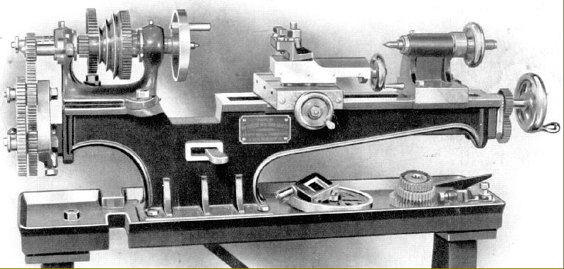
1908 Model the first with a compound slide rest (compound: of two- a cross slide topped by a top slide). Originally fitted with full-circle handwheels, this model quickly reverted to the more traditional cranked type shown in the picture below. An interesting comparison can be made between this version and the contemporary Colchester and Flather lathes of similar size.
|
|
|
|
|
|
|
|
|
|
|
 |
|
|
|
|
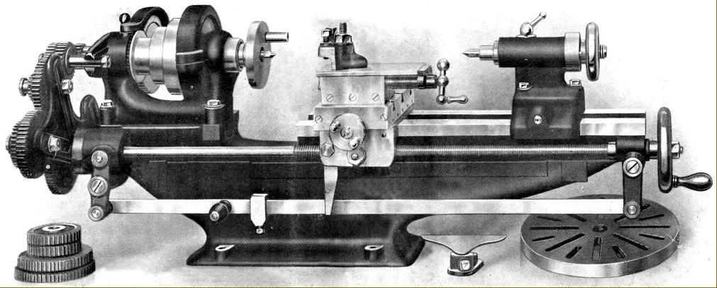
Drummond B Type circa 1912--1921. In reality, a completely new model that incorporated much fresh thinking about how a small lathe should be constructed.
|
|
|
|
|
|
|
|
|
|
|
|
|
|
|
|
|
|
Continued:
For the first ten years of production Drummond retained the basic structure of their original small flat-bed lathe largely unchanged, the vast majority being around 13" between centres - though very occasionally (just two so far) a long-bed model taking around 20" is discovered. However, every twelve months or so the factory made some small but significant changes were made to the specification and these alterations can be used to date early machines with re to the specification and a more detailed look at the first lathes and their development can be found here.
In 1912 Drummond introduced what was, in reality, a completely new model that bore the official title B Type (it was remarkable similar to the contemporary and early Colchester). The bed was made much heavier and stiffer, with the saddle thrust taken on a vertical surface on the inside of the front way. A bar was cast between the headstock bearings above the spindle pulley in an effort to improve rigidity (and reduce tool chatter) and the spindle-thread size was increased in size from 3/4" to 1". The leadscrew was moved from the middle to the front of the bed and the dog clutch fitted with a useful pre-set automatic throw-out facility. The changewheel arm (banjo) became V-shaped and allowed wider spacing of the changewheels - and hence the opportunity to use larger gears and make the carriage travel more slowly on its finest feed. Interestingly, the same original error - of trying to employ a cheap, single-slot changewheel arm - was made by South Bend on the introduction of their inexpensive Model 5 lathe in late 1931). As on all small Drummond lathes (including the much later Myford M-Type) the changewheels were 14 DP with a 14.5 degrees pressure angle; today, unfortunately, the standard pressure angle is 20 degrees so "off-the-shelf" gears will not match satisfactorily; if a new gears are required they have to be specially made. To connect the gears in pairs for a compound train each gear carried a pin and a pin hole./ As a point of caution, the pins are not parallel, but seated in tapered holes and, if driven out the wrong way, will fracture the gear. Redesigned, the tailstock was fitted with a guidance similar to that of the saddle - but the old-fashioned solid barrel retained. The original style of round-rope was left in place to complete a few more years' service, but the stand was entirely different and made much heavier and stiffer - however the original holes, that allowed belt passage on the lowest speed of the earlier models, were still present though no longer needed
In 1915 a thick gib 'block' was fitted at the front of the saddle in place of the original gib strip at the rear - which meant that tool thrust was now taken against a solid surface - not a strip of metal supported at three places by pointed screws - and the rigidity of the saddle-to-bed fitting enormously improved. A larger cross slide was also incorporated that had, at least in some cases, a micrometer dial fitted to its feed screw--though whether this was a standard fitting, or an accessory, is not clear. The true centre height was also increased to 35/8"
In 1914 the Mk. 1 "B.S. Type" was introduced for Admiralty use with a range of modifications to ease the difficulties encountered when turning in a rough sea. It was closely based on the standard B Type but fitted with a power-feed apron with both longitudinal and cross feeds taken from a shaft fitted below the leadscrew and geared to its left-hand end. A saddle traverse by hand-wheel to a rack and pinion was also included (but not the contemporary standard lathe) and a tumble-reverse mechanism fitted to the changewheel drive. The latter was neatly fitted to the slotted bracket on the headstock front that normally carried a stud to mount the extra changewheel required for left-hand screwcutting; when the tumble reverse unit became available on the B.S. it also entered the accessory lists for the standard machine. "BS-Type" lathe beds of the era can be identified by "pads" cast onto the front face of the bed to accept the power cross feed layshaft assembly. On the Mk. 1 BS the power-feed selector arm worked across the front of the apron whilst on much more common Mk. 2 it was positioned to hang downwards and indent into the underside face. There is no evidence that the BS was made available for civilian use, it being entirely absent from Drummond catalogues of the time.
B-Type Serial numbers from the Works official records:
1912 - possibly starting at 600 - one example as been found stamped 653
1913 - 1914 Serials 700 to 1516
1914 - 1916 Serials 1517 to 1731
1916 - 1918 Serials 1732 to 2003
1917 - 1918 Serials 2003 to 2173 (separate pages in ledger)
1918 - 1920 Serials 2173 to 2338
1919 Serials 2339** to 3002 (separate pages in ledger)
1919 - 1920 Serials 3003 to 3464
Serials 3465 to 4058 (separate pages in ledger)
1920 Serials 4059 to 4190 (separate pages in ledger)
Serials 4191 to 4224 (separate pages in ledger)
**Lathes up to No. 2339 had two machines against each Serial Number i.e. two different customers, dates and production ticket numbers for each Allowing for numbers duplicated, total production of the B-Type would have been around 4000 units. However, lost in the mists of time is when the digits were stamped: this could have been upon completion of a build, or immediately before dispatch - in which case unsold, obsolete models might have carried numbers from a sequence applied to newer version.
Continued below:
|
|
|
|
|
|
|
|
|
|
|
|
|
|
 |
|
|
|
|
|
|
|
|
|
|
|
|
Continued:
Drummond 1921
In 1921 Drummond again improved their smallest lathe and renamed it the M-Type, though this particular version, to be altered again for the 1925 season, was to have the shortest run of any model (save perhaps the original model produced in 1902 and first modified in 1904). The aim of the new alterations was to improved rigidity and resistance to tool chatter and the main changes focus on the headstock where a greater mass of metal was used, the futile over-arm brace removed and the flexible and poorly supported system of using two flat surfaces simply bolted together (buy which means the headstock could be rotated slightly) was abandoned. In its place was a positive location with a tongue on the base of the headstock located against a matching vertical surface on the bed - the whole assembly clamped down firmly with four bolts. Larger spindle bearings were employed the adjustment of which reverted to an earlier Drummond design where a large ring, screwed onto the outer end of the bearing, pulled it into the tapered headstock housing and provided a means of setting the clearance. Although the design appeared, externally, to be the same as used on the next and all subsequent version, it was different in a number of important details and had certain drawbacks. While the type that superseded it could (very cleverly) be adjusted for clearance (by the screwed ring) and then locked solidly into the headstock by means of a tapered key pushing into a tapered slot cut into the top of the bearings, this model had a parallel wedge; tightening the large ring drew the bearing into the housing in the usual way and so closed down the slot until it met the edges of the key. If the key was too narrow the bearing would lock and if too wide the clearance incorrect. In addition, even if the setting was perfect and the spindle rotated without play, the bearing was merely held into its housing and not expanded out tightly against the surround walls. The result was a tendency for cuts to chatter and only a change to the "expander bolt" design four years later solved the problem.
As an aid to heavier rates of metal removal a long-needed, three-step flat-belt drive replaced the by now hopelessly inadequate small-diameter round "gut" drive. The spindle nose was improved and fitted with a 1" x 12 t.p.i. thread backed by a 11/8" register designed to improve the rigidity of screwed attachments. The backgear ratio was changed from 20:60T to 22:66T and engaged by rotating an eccentric shaft instead of sliding into place. In place of having to reach for a spanner to disengage the 66t bull wheel from its embrace with the belt pulley, a cleverly designed "ramp" (that acted as a cam) was machined into a plate on the front of the gear. If everything was adjusted to slide easily, a swift push by a gnarled thumb against a knurled-edge knob was sufficient to persuaded the close-fitting engagement pin out of mesh with the pulley-flange. To engage direct drive the backgear was swung away and the knob merely moved slightly in the other direction - when a spring on the pin returned it automatically to engage with the pulley. The writer spent some time using one of the lathes and the speed with which backgear could be engaged and disengaged was a delight. The No. 1 Morse taper tailstock was also further increased in strength and the barrel diameter increased from 3/4" to 7/8". The previous rather crude screw-in barrel clamp gave way to a much more elegant and efficient "cotter" or "internally-split" locking device and some machines (but not, surprisingly, all) were given a hollow barrel to solve the problem of how to remove centres and chucks.
Although the T-slotted cross-slide casting was unchanged, the top slide (apart from the early-pattern clog-heel toolpost) was all-new: its feed screw was off-set to the side in order to provide a longer and slower-wearing nut (and allow the tailstock to come right up to the right-hand face of the cross slide) and its base given an improved (though still hard-to-read) degree-graduated scale on an inserted brass plate. The cross-slide feed screw handle was modified to have two finger grips and given a zeroing micrometer dial.
Although the changewheels remained unchanged from their 1902 specification, their studs, instead of being fitted with slow-to-remove, screw-on knurled-edge finger nut retainers, were fitted with a new design of (patented yet very simple) push-in "spring" holders - a design that was to be used until the end of production. On previous models the changewheel banjo arm had always been held in place by a crude through-bolt that simple ran up against the mounting boss, a design that made it difficult to get enough grip to stop the arm being moved sideways when heavy cuts were taken. This was now supplemented by extending the arm in a slotted curve at the back through which passed a stud and nut to ensure that it simply could not move - no matter how great the provocation. The treadle-driven flywheel was balanced and ran on a ball race, as did the "pitman" driving link, both changes helping the operator to maintain a good speed with less effort.
Continued below:
|
|
|
|
|
|
|
|
|
|
|
|
|
|
 |
|
|
|
|
|
|
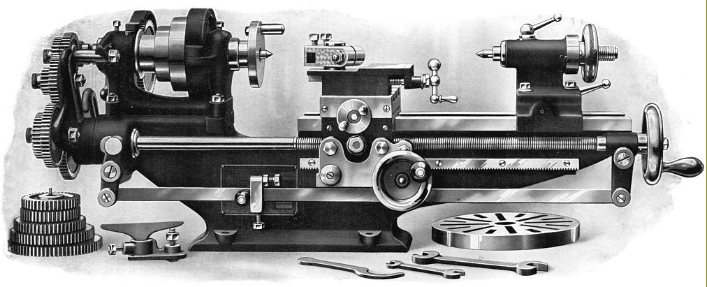
Final development: the Drummond M Type of late 1924 to 1943 with a leadscrew clasp nut and rack-and-pinion drive (20DP) to the carriage. Interestingly, a T-rest for hand turning was still considered by the makers to be an essential extra and included as standard with every lathe. This model was the first to have the simple but very effective "Norman Patent" quickly-adjustable toolpost.
Continued:
Drummond 1924
Further important changes were made in late 1924 that greatly improved the functionality of the lathe; these included the very important changes to the headstock bearings mentioned previously where the bearings were at last secured solidly into their housing when the clearance was set correctly, a leadscrew half-nut - this being a rather awkward assembly formed from a substantial bronze "swinging arm" located by a spring-loaded plunger on the left-side of the apron face. The nut (being of the "half" type and likely to be pushed out of engagement) was assisted by an upper thrust pad - a plain, half-round bronze unit retained by a massive bronze nut against the inside face of the apron. The carriage was further improved by the addition of a direct (though unfortunately high-geared) rack-and-pinion feed as originally fitted to the power-cross feed BS model. The top slide was thickened towards the rear, where it supported the feed-screw cross plate, and an enormous improvement made by incorporating, as standard, a quick-set toolholder of the "Norman Patent" type. The "Norman" was a simple but highly effective design and consisted of nothing more than a split, hardened steel block, with a broached square tool hole, arranged to slide up and down and clamp to a 1.25" diameter pillar cast integral with the upper section of the top slide. The cast-in post was also tapped down its centre for two purposes: originally to retain the maker's (very rare) milling slide and, later, to provide a means of clamping down a 4-way toolpost. Around the same time a long-bed version of the lathe was introduced - and also made available to the armed services in a now seldom-seen BS power-cross-feed version. Although further very minor modifications were made, this was the essentially the form in which the lathe continued until, in 1941 on orders issued by the Machine Tool Control Board, the Myford Company (whole lightly-constructed ML1 to ML4 range was judged insufficiently good for use by the armed services) were instructed to take over production for the remainder of World War Two. Oddly, Myford advertising literature has the change-over dating from 1941, yet Drummond Serial number records continue to 1943 - the explanation being either that production continued at two sites, or examples built by Myford were (for financial reasons) logged in the Drummond ledgers.
The last versions were built by Myford in the late 1940s with the final machines, which all seem to have been long-bed types, assembled from spares (according to the data on the changewheel cover) as late as 1954. Another small Drummond, made especially for the impecunious enthusiast, was the "Little Goliath" a very simple, not to say crude lathe, built down to a price and evidently, by the few surviving, not a complete sales success.
A very rare Model M has recently come to light, a geared-head version dated 1940, which bears all the hallmarks of either a pre-production prototype (or a machine modified by an enthusiast) and appears to have used the bed, tailstock, leadscrew and cross slide of the standard lathe, but with an entirely different headstock and apron.
Tony Griffiths
M-Type Serial Numbers - from the Works official records:
Introduced in 1921 and further developed in late 1924 in which form it continued unchanged until production was taken up by Myford in 1941/3. Some pre-production examples were manufactured during 1919/1920 - though how these were numbered is not known. Also lost in the mists of time is when the digits were stamped: this could have been upon completion of a build, or immediately before dispatch - in which case unsold, obsolete models might have carried numbers from a sequence applied to newer version.
1919 - 1920 Serials 1 to 66
1920 - Serials 67 to 131
1920 - 1922 Serials 132 to 1121
1922 - 1923 Serials 1122 to 1319
1923 - 1925 Serials 1320 to 1649 "A" suffix applied from No. 1405A--but at random
1925 - 1926 Serials 1450 to 1887
1926 - 1927 Serials 1897A to 2226A
1927 - 1929 Serials 2227A to 2685A
1929 - 1931 Serials 2686A to 2949A
1931 - 1933 Serials 2950A to 3345A
1933 - 1935 Serials 3346A to 3675A
1935 - 1937 Serials 3676A to 4071A
1937 - 1939 Serials 4072A to 4203A
1939 - 1941 Serials 4204A to 4401A
1941 - 1942 Serials 4402A to 4467A
1941 - 1942 Serials 4468A to 4592A (Separate page in ledger)
1943 - Serials 4534A to 4592A
A pattern machine (presumably a sample) is recorded as being dispatched to Myford on March 25th, 1943 with the final Drummond production M-type sent to the Admiralty on the June 30th of the same year..
To see an inspection and measurement test of a 1907 Drummond, click here.
|
|
|
|
|
|
|
|
|
|
|
|
|
|
 |
|
|
|
|
|
|
|
|
|
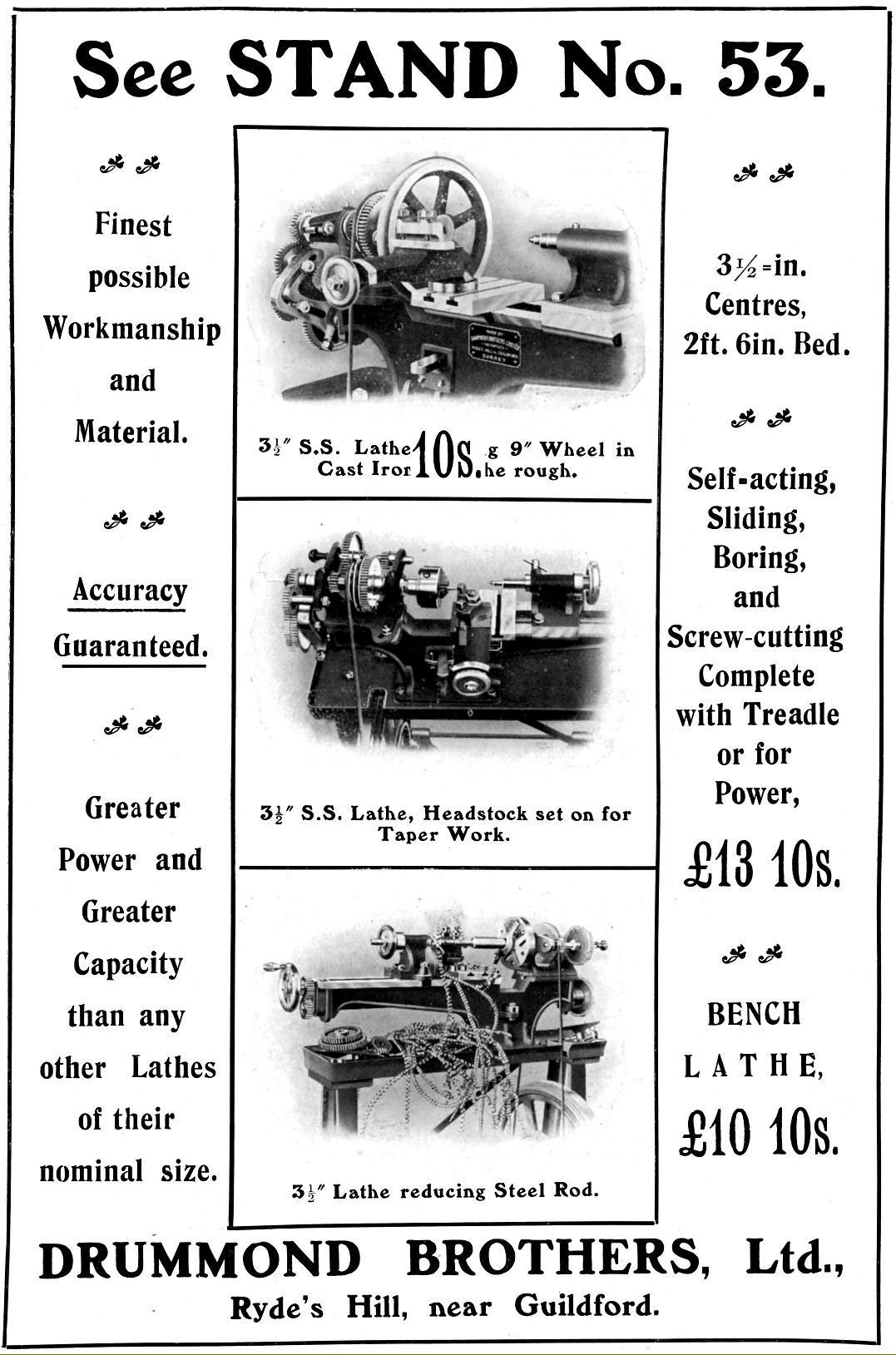
Drummond Brothers advertisement from the Model Engineer Exhibition of 1907
|
|
|
|
|
|
|
|
|
|
 |
|
|
|
|
|
|
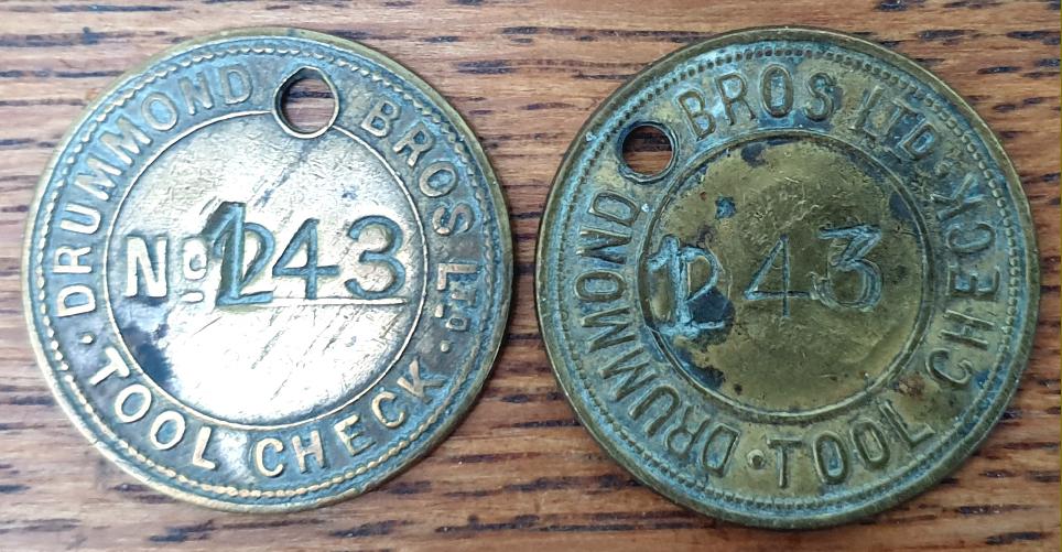
A Drummond factory "tool check" . These were used as a security measure, the number on the badge being that of an employee who, when he went to the stores to withdraw a tool, or other item, exchanged the badge for the requested item. Responsibility for the safe return of the tool then rested on the employee. No return? A scolding from the foreman followed by a wage reduction
|
|
|
|
|
|
|
|
|
|
|
|
|
|
|