 |
|
|
|
|
|
|
|
|
|
|
|
|
|
|
|
|
|
|
|
|
|
|
|
|
|
|
|
|
|
|
|
|
|
|
|
|
|
|
|
|
|
|
|
|
|
|
|
|
|
|
|
|
|
|
|
|
|
|
|
|
|
|
|
|
|
|
|
|
|
|
|
|
|
|
|
|
|
|
|
|
|
|
|
|
|
|
|
|
|
|
|
|
|
|
|
|
|
|
|
|
|
|
|
|
|
|
|
|
|
|
|
|
|
|
|
|
|
|
|
|
|
|
|
|
|
|
|
|
|
|
|
|
|
|
|
|
|
|
|
|
|
|
|
|
|
|
|
|
|
|
|
|
|
|
|
|
|
|
|
|
|
|
|
|
|
|
|
|
|
|
|
|
|
|
|
|
|
|
|
|
|
|
|
|
|
|
|
|
|
|
|
|
|
|
|
|
|
|
|
|
|
|
|
|
|
|
|
|
|
|
|
|
|
|
|
|
|
|
|
|
|
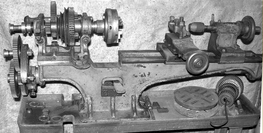
Introduced in 1902 the Drummond flat-bed 3.5" x 16" (and rare 20-inch version) was, in its various guises, to continue in production for almost half a century. Although often called the B-Type that designation did not, strictly speaking, apply until the appearance of a much-modified lathe in 1912 and after the introduction of the Round Bed, in 1908, which Drummonds called the A-Type. However, the maker's catalogue description, "31/2-inch Centre Back Geared, Self-acting Sliding, Boring, and Screwcutting Lathe" although accurate, is a little long for handy use, so for the purposes of easy reference to the very first flat-bed lathes we might call them "Pre B-Type Flat Beds". A well-thought-out machine, made of good-quality materials, the first small Drummond was obviously designed by engineers familiar with the needs of their intended market and, in many respects, incorporated refinements and features previously only found on much larger and more expensive lathes. Instead of a direct connection between changewheels and leadscrew the drive was taken first through "power shaft" (with a dog clutch at the headstock end) that ran the length of the bed and engaged a gear at the tailstock end to transmit its drive up to the leadscrew that sat between the bed ways. This arrangement had the advantage of allowing the leadscrew, as on many very high-class toolroom lathes of later years, to transmit its pull to the carriage almost directly under the middle of the saddle on the shortest least flexible route possible. One very rare model, a long-bed version, incorporated an extra support foot towards the tailstock end. Because the bed was too long for the operator to comfortably turn the normal carriage drive handle (at the end of the bed), the support foot incorporated a worm-and-wheel drive that engaged with the powershaft.
Several changes to the headstock casting and its bearings were made in the first years of production: on the first model, the whole unit was decidedly flimsy, with cast-in bracing on the horizontal face between the bearing uprights and each bearing pinched by a bolt that passed beneath it - an identical arrangement can be seen in the pictures of the company's contemporary (and very rare) circa 1900 4-inch model . The bed was also of minimal proportions - and so slight in depth at the tailstock end that a good deal of the central drive shaft beneath the leadscrew was exposed. However, this first design did not last long and, as early as 1903/4, the headstock casting had been strengthened and the bearings changed to a type with a taper on the outside face and a screwed ring and serrated ring nut on the end. By tightening the ring nuts the bearings were pulled into the headstock casting and so closed down to set the running clearance on the 3/4" x 8 t.p.i. spindle. Unfortunately, this beautifully-engineered arrangement also failed to survive and, by 1905/6, Drummond had cheapened the assembly to allow the bearings to be drawn in by through-screws that pulled on thick steel washers; this inferior design, though prone to chatter if not perfectly adjusted, lasted until the introduction of the "M-Type" in 1921. Although most pre-1912 lathes had a 3-step headstock pulley for drive by a 1/4" round leather (gut) drive examples are known of machines with 2-step pulleys that took a much larger belt; though not mentioned as an option in any known catalogue, these lathes would undoubtedly have been intended for tackling heavier work.
There was no compound slide; instead the swivelling tool slide could be locked by a single bolt into one of two T slots on the saddle (which doubled as a small but useful boring table) and slid into the most convenient position for the job in hand; it was even possible to swing it right around and use it as a rear tool post for parting off with an inverted tool (a decided improvement on trying to do that most difficult of jobs from the front.)
In 1905 Drummond moved from their original Pinks Hill site (actually the country home of Arthur Drummond) to Rydes Hill - a change that was reflected in the company's machine nameplates; however, knowing from retired-piece Drummond workers just how parsimonious their employer was, it is likely that older badges would have been used up first - so this handy dating pointer can only be considered approximate.
Continued below:
|
|
|
|
|
|
|
|
 |
|
|
|
|
|
|
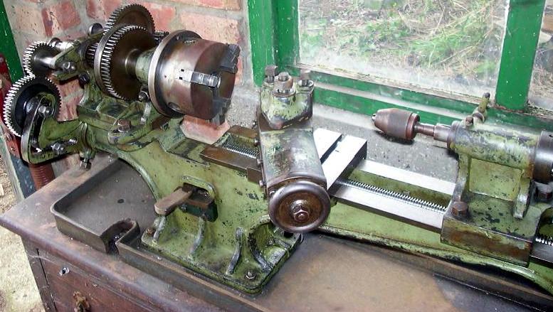
Above: the earliest type of flat-bed 3.5" centre-height Drummond had a distinctive headstock with pinch bolts passing beneath the bearings and cast-in bracing struts on the face between the bearing uprights (exactly like the contemporary Drummond 4-inch. The first beds were of especially light construction with the short section of underside at the headstock end almost parallel to the ways and at the tailstock end rising so close to the top surface that it exposed, in side elevation, a good deal of the power shaft that lay beneath the leadscrew.
|
|
|
|
|
|
|
|
|
Continued:
In 1906, having presumably settled into their new premises, further changes were made to the lathe's design and the maker's publicity material made much of both the new headstock spindle bearings (previously explained) and the improved bed casting that, being considerably thicker and more heavily constructed, was much stronger than the original. The two beds are easily distinguished with the earlier having its underside edge parallel to the ways at the headstock end and, at the other, rising in a graceful arch to become very close to the top surface (exposing both top and bottom surfaces the shaft drive beneath the leadscrew) before looping down to form a vertical flat mounting surface for the leadscrew bracket. The new bed had a distinctive downward curl at the headstock end and a rather deeper wall at the tailstock end - these features being an easy way to determine from a photograph if a lathe really is one of the rare surviving first examples. Sadly, the elegant hardwood (or horn) knob on the backgear shaft disappeared to be replaced by a tapered, one-piece steel handle - and an altered design of leadscrew clutch, with two positions instead of three, was introduced. The tailstock was modified with a longer bracket extending from the base casting and the loose clamp, instead of being machined from a block of steel, was now made of cast iron; unfortunately, the convenient locking handle was omitted and replaced by a nut that required the application of a loose, self-hiding spanner. The simple knock-in barrel-guide pin was moved from the side of the casting to the top; photographs of a circa-1906 model with some of these features can be seen here.
Changewheels ran directly on plain studs and were retained by circular, knurled-edge nuts. The mounting bracket was L-shaped, a design foible left over from Victorian times that made it difficult to set up a very fine feed to the carriage drive. Changewheels supplied as standard consisted of: 20t, 30t, 35t, 38t, 40t, 45t, 50t, 55t, 60t and 65t. To generate metric threads an additional 63t changewheel could be purchased at extra cost.
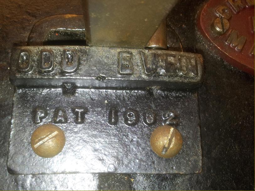
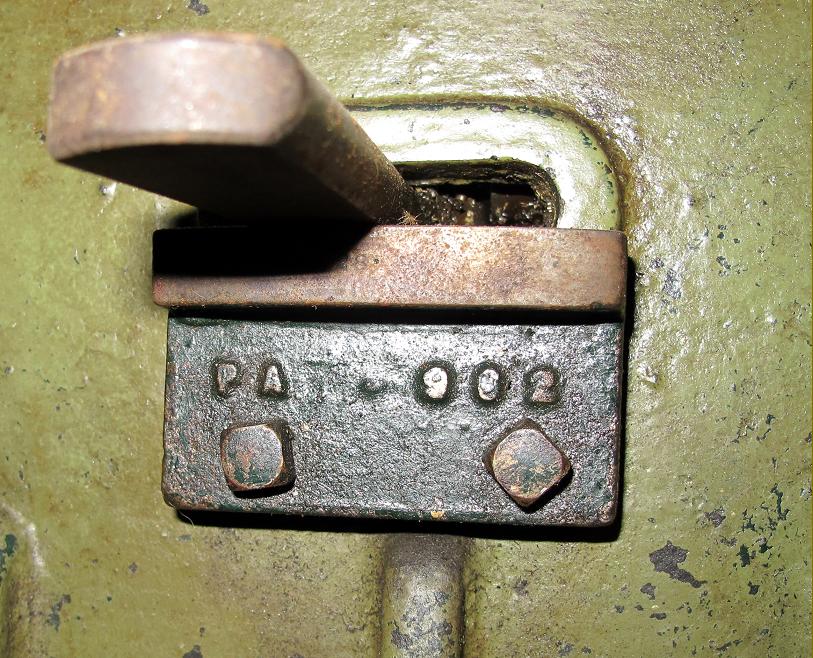
In about 1907 the largely ornamental bracket beneath the leadscrew dog-clutch handle, held in place by two square-headed bolts, was omitted. On the very first models, from early in 1902, this had (as cast-in lettering) "ODD" to the left, "EVEN" to the right with beneath, in smaller letters, "PAT 1902". As the years passed the upper line was deleted leaving just the lower, with even that being incomplete was the casting pattern must have been damaged. Also fitted to the first examples was a round badge, in cast bronze, proclaiming Drummond Bros. Maker - the same fitting being used on the Company's first series production lathe, the double-height bed 5-inch. Another change circa 1906/7 was a modification to the single swivelling top slide modified to reduce the bending moment; this being achieved by bringing the clamping stud and nut in line with its slideway. As a final touch, the base of the slide was given a set of inscribed degree graduations. It was 1908 before a compound slide rest was finally introduced - initially with round handwheels and then with the "cranked" type, a design that was to become a Drummond 'trade-mark'. Although some of the above changes can be found in contemporary advertisements, many cannot and numbers of lathes have been found where the specifications overlap and the year of production is uncertain. For example: lathes with a graduated base to the top slides, but still with the dog-clutch lever bracket in place; or a compound slide rest on a lathe with the older-style bearings. It is also entirely possible that the factory used up obsolete parts before a modification became permanent. Alternatively, customers may have ordered a cheaper specification or returned them to the factory for repair, alteration or updating; or rebuilt and adapted them over the years using whatever later parts came to hand.
Able to be swivelled on the bed the headstock could be combined with the fully-adjustable tool slide to allow the easy cutting of short tapers and tapered threads. However, it took until 1912 before the factory realised that fitting a locating dowel would help their customers in the important task of return the setting to zero. The gap in the bed could accommodate a piece of material a little over 9.5" in diameter and 3" thick and it was possible to set the tailstock over for long, fine-taper work. Supplied with the lathe as standard were: a faceplate, a small-angle plate with vertical T slots, catchplate, travelling steady, hand rest, two No. 1 Morse taper centres, a drive belt and spanners.
Although usually illustrated mounted on a self-contained treadle-and-flywheel stand, various kinds of wall and ceiling-mounted countershaft units were also available for those lucky enough to have either a stationary engine or even (though at great cost) an electricity supply and an electric motor. Although in its first incarnation this was a thoroughly well-specified product, it was substantially improved in 1912 and reached its final version through the two major rethinks of 1921 and 1925. It continued in production until 1942 when, overwhelmed with war-time demand for their high-speed production lathes, Drummond was forced by the Ministry of Supply (who controlled all material and machine-tool allocations) to pass the rights over to Myford. Advertised as the "Myford M-Type" it became known in model engineering circles as the "Myford-Drummond M-Type" - a general history of the machine can be followed on the Drummond/Myford M Page. A particularly fine and original early 31/2" example still in regular use in Germany (and with just two owners) can be seen here.
Surprisingly, having regard to the popularity of these early Drummond lathes and their domination of the top end of the amateur market, it is surprising that no third-party appears to have made any effort to market accessories - though there was the exception of a powered shaper, driven from the headstock spindle, that attached to the bed - though this was a unit that could be supplied with fittings for a variety of other contemporary models. Finally - how many were made? A comment in a magazine article of 1921 quoted: Fifty of the new type 31/2-in lathes (this would refer to the M-Type) are made each week and nearly that number of the popular 4-in (Round-bed) model". However, the manufacture's figures show that early models, until 1912, were produced in limited numbers, possibly only 600 or 700 units. The B-Type, from 1912 to 1921, was much more successful, with around 4000 manufactured. The M-type (as made by Drummond, not Myford) ran to about 4600, giving a total for the model of approximately 9200; how many additional examples Myford made is not known.
Yearly figures from the lathe's introduction in 1902 until the heavily revised B-Type of 1912 are lost, but records survive of some older models dispatched from the works during 1914 - presumably from old stock not sent out to dealers. These were Serials: 593, 609, 614, 615, 629, 633, 643, 644, 648, 651, 662, 664, 668, 669, 671, 675, 681, 682, 684 and, in 1915, No. 501.
As B-Type Serial numbers started with 700, it might be deduced that only some 600 odd of the first model were produced during its ten-year run. At an average of just over one per week, that does seem an unusually low figure
Although the B Type was replaced in 1921 (by the new M-Type) it is believed that production had already stopped in 1919 with large stocks unsold. Most were gone by the end of 1920, though a few lingered on until 1926 - the last sold being No. 4226. Lost in the mists of time is when the digits were stamped: this could have been upon completion of a build, or immediately before dispatch - in which case unsold, obsolete models might well have carried numbers from a sequence applied to newer version.
B-Type production numbers were:
1913 - 1914 Serials 700 to 1516 (the start number is unknown but may have been 101)
1914 - 1916 Serials 1517 to 1731
1916 - 1918 Serials 1732 to 2003
1917 - 1918 Serials 2003 to 2173 (these were found in separate, out-of-sequence pages in ledger)
1918 - 1920 Serials 2173 to 2338
1919 Serials 2339 to 3002 (separate pages in ledger)
1919 - 1920 Serials 3003 to 3464
Serials 3465 to 4058 (separate pages in ledger)
1920 Serials 4059 to 4190 (separate pages in ledger)
Serials 4191 to 4224 (separate pages in ledger)
With some numbers duplicated, total production of the B-Type was around 4000 units.
To see an inspection and measurement test of a 1907 Drummond, click here..
|
|
|
|
|
|
|
|
 |
|
|
|
|
|
|
Very early headstock with below-the-bearing clamp-bolts
|
|
|
|
|
|
|
|
 |
|
|
|
|
|
|
Dog clutch support bracket as it appeared in early 1902
|
|
|
|
|
|
|
|
 |
|
|
|
|
|
|
By late 1902/3 the casting pattern must have been damaged with the result being the incomplete lettering seen here
|
|
|
|
|
|
|
|
 |
|
|
|
|
|
|
Casting bronze, only the earliest of the new flat-bed models carried a Drummond badge - one identical to that used on the Company's first series production lathe, the double-height bed 5-inch
|
|
|
|
|
|
|
|
 |
|
|
|
|
|
The same early model an the photograph above, but suspected to have come from the second-edition catalogue showing a heavily art-worked picture disguising the change in the headstock casting and bearings--but not the bed, which is shown as the earlier type with the short length of underside at the headstock end finished in a section parallel to the ways and, at the tailstock end, rising to become very close to the ways before looping down to form a flat vertical surface for the leadscrew bracket. It is likely that the new headstocks were fitted for a while to earlier pattern beds--though for how long it is impossible to say. The simple, wooden packing pieces being used to mount the motor-cycle cylinder might seem an amateurish effort but was (and remains) a highly effective way of holding a fragile component without damage. The pin that limited the travel of the dog-clutch lever (it can be seen protruding through the bed immediately below the gap) was quickly dropped - as was the unnecessary support plate itself in 1907.
|
|
|
|
|
|
|
|
|
|
|
 |
|
|
|
|
|
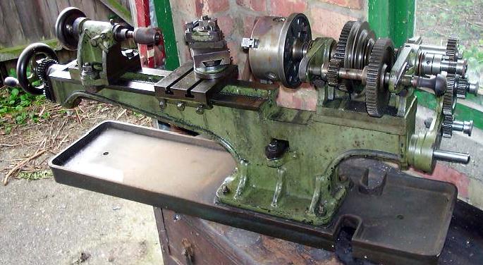
A 1907/8 model showing the optimum metal removal capability when using the proper tool on the right material at the correct speed - and with a delicate rate of feed, skilfully applied. Although most pre-1912 lathes had a 3-step headstock pulley for drive by a 1/4" round leather (gut) drive examples are known of machines with 2-step pulleys that took a much larger belt; though not mentioned as an option in any known catalogue, these lathes would undoubtedly have been intended for tackling heavier work.
|
|
|
|
|
|
|
|
|
|
|
 |
|
|
|
|
|
|
|
|
Here the headstock is seen set over and a short taper being turned. The round leather rope drive from the rim of the foot-operated treadle drive allowed for a certain degree of twist in its drive. The sliding backgear was fitted with an elegant horn or hardwood handle.
|
|
|
|
|
|
|
|
|
|
|
|
|
 |
|
|
|
|
|
A 1908 Model with the new-for-that-year compound slide rest - note that the "support plate" bracket under the leadscrew dog-clutch lever is no longer fitted and the more substantial bed in comparison with the machines illustrated above - most obvious being the increase in depth between the bed ways and the top of the radius at the tailstock end and the down sweep of the casting at the headstock end.
|
|
|
|
|
|
|
|
|
|
|
 |
|
|
|
|
|
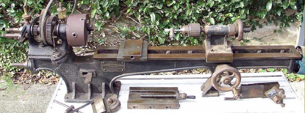
This very unusual and ultra-rare long-bed model has a support foot part way down the bed at a point that incorporates a hand drive to the power-shaft beneath the leadscrew. Never advertised (as far as can be ascertained) few can have been made with only two known, one in the UK the other in New Zealand.
|
|
|
|
|
|
 |
|
|
|
 |
|
|
|
|
|
|
|
|
|
|
|
|
|
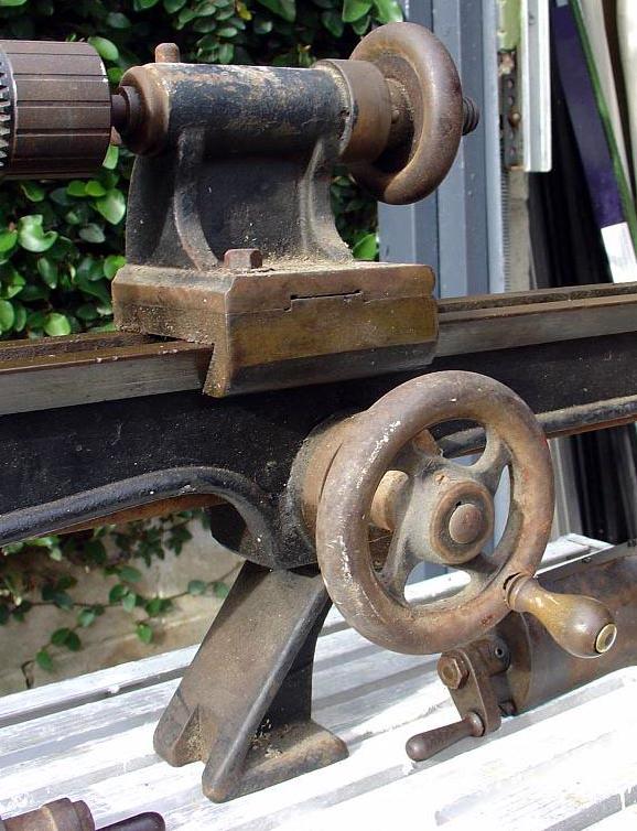
Hand-drive to the power shaft that, connected by gears to the leadscrew at the tailstock end of the bed, drove the carriage
|
|
|
|
|
|
|
|
|
|
 |
|
|
|
|
|
The first owner of this little used, post-1904 Drummond fitted a graduated handwheel to the single swivelling tool slide and a neatly made brass plate, precisely let into the end bracket, to carry a zero mark.
|
|
|
|
|
|
|
|
|
|
|
|
|
|
|
The second version of the Drummond flat bed illustrated above was considerably modified with new bed, headstock and tailstock castings and redesigned headstock bearings. More details of these modifications and the machine's development can be found by following the hyperlinks above or looking here.
A warning to those who restore old machine tools - when it's time to remove the old paint, be wary about using paint stripper. Old-time manufacturers were not so concerned about the quality of the castings they used - and had no qualms about applying a filler composed of lamp black, fiddler's rosin and iron filings or "borings" to cover up faults in the metal (an alternative was a mixture of sulphur, cast iron siftings and sal-ammoniac). The first mix, almost universally used, was known in the foundry trade as 'Beaumont's Egg' , possibly from a corruption of "beamontage", a filler used in the furniture trade. To hide minor faults in a casting Beaumont's Egg was run into blow holes and porous areas by melting it with a hot iron bar followed by rubbing down to make it almost undetectable. As an interesting aside the supplier of the cast-iron columns that collapsed in the Tay-bridge disaster used 'Beaumont's Egg' to cover his poor workmanship. Hence, the difference between a good foundry and a poor might have been the point at which a defect was accepted as being too large to fill, leading to a rejection of the casting. Unfortunately, early-filler soaks up paint stripper like a sponge - but then, being well absorbed into what are almost certainly porous castings, the metal refuses to let go; the result is that paint will not stick and the filler has to be mechanically removed - another hazardous operation. Be wary of using a sanding disc or powered wire brush - even sound casting were often lead filled to smooth out the imperfections - and you don't really want clouds of that flying around the workshop, do you?
|
|
|
|
|
|
|
|
 |
|
|
|
|
 |
|
|
|
|
|
|
|
The Allen socket screws for gib strip adjustment are most definitely non-original ….
|
|
|
|
|
|
|
|
|
|
|
|
|
|
|
The tool slide, whilst undeniably elegant, was hardly the most rigid of structures with the mass cantilevered away at 90-degrees from the mounting boss and unsupported by any form of bracing
|
|
|
|
|
|
|
|
|
|
|
 |
|
|
|
|
 |
|
|
|
|
|
|
|
|
|
|
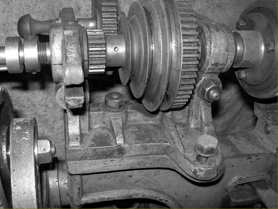
Rear of the headstock showing the sliding engagement for backgear and (on the back of the bed) the pivot for the leadscrew engagement dog clutch.
|
|
|
|
|
|
|
|
|
|
|
|
|
|
Drive from changewheels to carriage was by a dog-clutch-engaged shaft that passed beneath the bed and drove the leadscrew above it through exposed 1-to-1 gearing.
|
|
|
|
|
|
|
|
|
|
|
|
|
|
 |
|
|
|
|
 |
|
|
|
|
|
|
|
|
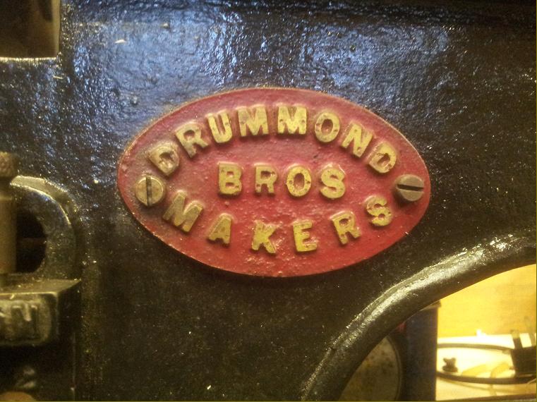
Maker's plates are often missing or damaged on early machines but this immaculate example shows that the lathe was built at the second home of Drummond, Ryde's Hill, near Guildford in Surrey.
The original "frosting" marks are still visible on the bed.
|
|
|
|
|
|
|
|
|
|
|
|
|
|
|
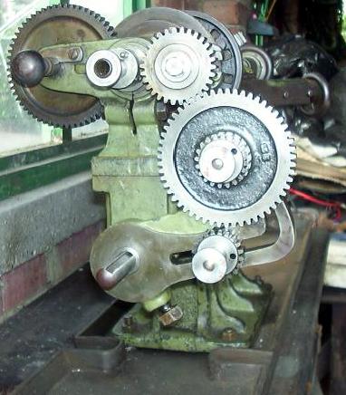
Compound reduction gearing set to give the highest possible numerical ratio between headstock spindle and leadscrew.
For those unfamiliar with the technique, the largest gear is fitted on the leadscrew end, the second largest runs on the stud above whilst the third largest engages with the spindle gear. The smaller gears are arranged in a similar way: the smallest gear shares the uppermost stud on the changewheel arm with the second smallest (hidden in the picture on the inside of the lower stud) driving the leadscrew gear.
|
|
|
|
|
|
|
|
|
|
|
 |
|
|
|
 |
|
|
|
|
|
|
|
|
|
A distinctive L shaped "banjo" arm carried the changewheels. Early nuts and bolts were rather "fuller" than the later slimmed down versions introduced as a material-saving exercise during the First World War.
|
|
|
|
|
|
|
|
|
|
|
|
|
A quaint Drummond custom was to leave the headstock oiler nuts without covers - allowing swarf and dirt to drop into the bearings. Here a conscious owner had made simple drop-in plugs to offer some degree of protection.
Bearing oilers doubled as a bearing expanders; they were screwed in until lightly engaged with a slot in the bearing wall - and the bearings adjustment rings then turned until the spindle showed some drag . Screwing the adjuster fully in expanded the bearing out slightly against the tapered wall of its housing and gave the correct clearance.
A little nick in the edge of the largest pulley rim indicated the position of the slot into which the bull wheel locking pin engaged.
|
|
|
|
|
|
|
|
|
|
|
 |
|
|
|
|
|
|
 |
|
|
|
|
|
|
|
|
|
Rear view of headstock showing the backgear spindle-locating pin
|
|
|
|
|
|
|
|
|
|
|
|
|
|
|
The slotted arm protruding from the rear spindle bearing was provided to carry a stud on which a changewheel could be mounted to reverse the leadscrew drive - and so cut left-hand threads.
|
|
|
|
|
|
|
|
|
|
|
 |
|
|
|
 |
|
|
|
|
|
|
|
|
|
On the early lathes the tailstock clamped to the same dovetail ways used by the saddle. The clamping plate was machined from a block of steel, but from 1906 was replaced by an iron casting. Note the pin and hole in the changewheel for joining gears in compound trains
|
|
|
|
|
|
|
|
|
|
|
|
|
The drive to the leadscrew was taken from the changewheels by a shaft to a dog clutch immediately below the bed gap. From there the shaft continued to the end of the bed - where it emerged to drive upwards to the leadscrew though a pair of gears.
|
|
|
|
|
|
|
|
|
|
|
|
|
|
|
 |
|
|
|
|
|
 |
|
|
|
|
|
 |
|
|
|
|
|
 |
|
 |
|
|
|
|
|
|
|
|
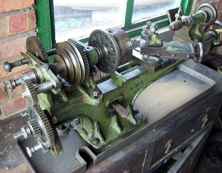
Below - A Drummond B-Type circa 1906
showing some of the modifications introduced during that year
Pictures of another example here
|
|
|
|
|
|
 |
|
|
|
 |
|
|
|
|
|
|
|
|
In order to stiffen the assembly a modified top slide was introduced. This had the clamping bolt in line with the slide whereas the earlier version had its offset well to one side, allowing a degree of leverage and hence spring to be introduced into the assembly. Note the thin nut clamping the top slide and the degree markings engraved around the circular base.
|
|
|
|
|
|
|
|
|
|
|
|
|
|
|
Modified tailstock with extended bracket on the base plate and a cast-iron clamp.
|
|
|
|
|
|
|
|
|
|
|
|
|
|
 |
|
 |
|
|
|
|
|
|
|
|
|
The simple knock-in pin which guided the barrel was moved from the front to the top of the casting.
|
|
|
|
|
|
|
|
|
|
|
|
|
|
New draw-in bearings - but still with the wooden (revolving) handle on the end of the backgear shaft
|
|
|
|
|
|
|
|
|
|
|
|
|
|
|
|
|
|
|