 |
|
|
|
|
|
|
|
|
|
|
|
|
|
|
|
|
|
|
|
|
|
|
|
|
|
|
|
|
|
|
|
|
|
|
|
|
|
|
|
|
|
|
|
|
|
|
|
|
|
|
|
|
|
|
|
|
|
|
|
|
|
|
|
|
|
|
|
|
|
|
|
|
|
|
|
|
|
|
|
|
|
|
|
|
|
|
|
|
|
|
|
|
|
|
|
|
|
|
|
|
|
|
|
|
|
|
|
|
|
|
|
|
|
|
|
|
|
|
|
|
|
|
|
|
|
|
|
|
|
|
|
|
Not the cheapest Drummond lathe ever produced (that was the Little Goliath of the 1920s) the inexpensive Type A "Round Bed" was announced in the Model Engineer Magazine of May 21st, 1908. Publicised, with some fanfare, as the first £5 screwcutting lathe, it was labelled by its makers as the All Round Utility and was to become famous as the most affordable machine for generations of British model engineers taking their first tentative - and usually impecunious - steps into the hobby.
The Round Bed - or a copy - was also built in Australia; this was a lathe that, while closely following the general design of the English version, was different in almost every detail. The only one found to date, a long-bed type, has a neatly integrated backgear assembly and every major casting altered - together with a riveted-on bronze badge that proclaims just Drummond, with no address. Even the arrangement of the changewheels, though carried on the usual single-slot bracket, are different with the compounded pairs joined not by the usual Drummond pin, but a key. The latter details leads the writer to believe that this must have been a developed and improved copy - though if Arthur Drummond had a hand in its design is not known. Arthur, the more active of the two Drummond brothers, visited Australia in the early years of the 20th century and was involved, while there, with the design of a lathe headstock with a spindle large enough to pass the pipes used to pump water out of the many wells then in existence. It is entirely possible that amongst his luggage were proposed designs for various models including improvements to existing models. If any reader suspects that they might have such a lathe (or other interesting variation on the standard theme), the writer would be very interested to hear from you.
A simple 4" x 11.25" machine (but lacking backgear in the UK) it was made until 1943 using, in that time, three increasingly strong headstock castings together with modified spindle bearings - yet with only minor changes to the rest of the specification. Also offered, with production starting late in 1923, was a long-bed version with 24 inches between centres, the announcement of its availability being made in January, 1924.
Although designed to sell at the bottom end of the market, the lathe was not cheapened in any way but built to the usual honest, practical, Drummond standards. The heart of the lathe was the heavy, round, 3" diameter cast-iron bed, ground to within 1/1000" on an American Norton cylindrical grinder and formed with a bevelled slot along its underside to locate the tailstock and carriage. The leadscrew passed through the centre of the bed and was engaged by a dog clutch, the operating lever of which protruded through the headstock casting below the front spindle bearing. The end of the leadscrew was fitted with a large, un-graduated wheel for hand operation with the finger grip made from horn or hardwood. However, because the leadscrew had a right-hand thread, turning the handle produced a cack-handed motion - rotating it anti-clockwise resulting in the carriage being moved nearer to, rather than away from, the chuck. Needless to say, after a few ruined jobs and anxious moments most owners quickly adapted to this quirk of the design.
With its top formed as a boring table, the "saddle" assembly could be partially rotated round the bed - which movement had the effect of altering the height of the table in relation to the spindle centre line. It was thus possible to make vertical adjustments when setting work on the boring table and make making minor changes to the setting of the height and angle of turning and milling cutters, etc. This versatility of movement had some interesting consequences, it even being possible to mount and rebore the (detachable) 4-cylinder block from an Austin 7
A compound slide rest was never offered by the makers for the Round Bed; instead, the single tool-slide (a common design trait at the time on inexpensive lathes and also used on early versions of the 3 ½" flat bed) was mounted on a vertical bar that passed through an extension to the front edge of the saddle. This extension, being split and formed into a clamp, allowed the slide, which had a degree-graduated base, to be raised, lowered and swivelled. However, the lack of a proper swivelling top slide was met by third-party accessory makers including a unit from Bailey & Co. trading from 53 Chester Park, Fishponds, Bristol. The toolpost was self-contained (which meant that no tool-holding strains were carried by the central bolt) and fitted with a round hole for boring tools as well as the usual rectangular slot.
Continued below:
|
|
|
|
|
|
|
 |
|
|
|
|
|
|
Late-model Round bed with the headstock spindle running direct in the cast-iron of the headstock. The lathe is shown with the stud in place to cut left-hand threads
|
|
|
|
|
|
|
|
 |
|
|
|
|
Continued:
On early lathes the top of the headstock was machined flat and the bronze bearings bolted to it. On the very first examples, the bearings were in two parts, with the upper and lower sections separated by adjustment shims; next came a simplified type with the bearings formed in one piece with the clearance set by a slot and pinch bolt. The large bolt at the front was screwed into the headstock casting while at the back two small screws were used to held the rear section do this wore rapidly and Drummond invited owners to return their complete lathe for modification with a hole reamed directly in the cast iron - alignment problems obviously compromising any attempt to fix the tailstock on its own. Another minor difference on the latter headstock was the method of locating the bearing caps, some being found with small studs screwed into the headstock casting and others with locating dowels - though it is not known which came first.
From correspondence in contemporary Model Engineer magazines, it has been discovered that all early examples were fitted with a white-metal liner for the tailstock spindle. Unfortunately, though a good idea, centre height on the Round Bed can vary by up to 1/8" from nominal, it almost certainly being the case that selective assembly of parts was necessary to get everything lined up.
In 1919/20 - when the Serial number prefix changed from "MCHA" to "O" - the design underwent some revision and improvement: the left-hand headstock bearing "arm" was increased in size; the bolt-on bronze headstock bearings abandoned and the spindle made to run direct in the cast iron of the headstock with the clearance set by nipping up a clamping screw at the rear. Other changes introduced at the same time (although, as with the flat-bed lathes, there would inevitably have been some overlap) were a reduction in the number of T slots in the cross slide from 4 to 3; a modification to the tailstock where the barrel was increased in diameter (and the previous use of a white metal liner abandoned); the adoption of push-in spring retainers on the changewheel studs instead of the previous slow-to-operate, screw-on rings (that tended to come undone when the changewheels were run "in reverse"); the replacement of the detachable changewheel reversing arm by a forward-facing forked bracket cast as part of the headstock - and the very overdue use of a gib strip with adjustment screws on the tool slide. Very early examples appear to have had a slightly different spindle with a thread 1.040" in diameter by 14 TPI (with no plain section to act as a register before the abutment face) and bored out to 0.325" rather than 0.375". The spindle was then modified to carry a 7/8"-diameter, 10 t.p.i. thread on the nose and given a ground (rather than turned) finish on the bearing surfaces; as standard it was not hollow, but the 0.375" diameter hole could be ordered for a small extra cost. Later spindles (fitted to lathes where it ran direct in the headstock casting) had a 3/4"-diameter by 10 t.p.i thread with a small plain register about 0.25" long before the abutment face. If you find a Round Bed that differs from these specifications do not be surprised; over the years many have been fitted with replacement spindles and the factory did not seem averse to the occasional experimentation with altered dimensions. The three-step cone pulley on all models was in cast iron, rather heavily made with diameters of 6", 4.5" and 3.5" and driven by a 1" wide belt.
From the start of production until 1925 a set of eight changewheels was provided as standard: 20t, 24t, 28t, 32t, 36t, 40t 44t and 64t with an extra set to generate metric pitches (at additional cost) of 25t, 35t, 45t 50t and 63T. Thereafter a set of 9 gears was supplied - which included those necessary for metric threading: 20t, 25t, 26t, 30t, 35t, 40t, 45t, 50t and 66t giving a threading range of: 5, 6, 7, 8, 9, 10, 11, 12, 13, 14, 16, 18, 20, 24, 26, 28, 32, 36 and 40 t.p.i. Because early headstock castings lacked the cast-in slot provided on later examples (that accepted a stud on which to run an extra changewheel to produce left-hand threads) the makers offered (at extra cost) a slotted bracket that bolted to the left-hand face of the headstock. This positioned the extra "reversing" changewheel in a rather distinctive fashion above the others. As on all small Drummond lathes the changewheels were 14 DP with a 14.5 degrees pressure angle; today, unfortunately, the standard pressure angle for gears is 20 degrees so ones "off-the-shelf" will not match and, if new gears are required, they have to be specially made. However, the gears from all 3.5-inch flat bed lathes from 1902 to 1946 will fit.
Continued below:
|
|
|
|
|
|
|
|
|
|
|
|
|
|
|
|
|
|
 |
|
|
|
|
 |
|
|
|
|
|
|
|
|
The very first Round Bed headstock bearings were in two parts with a bolt-on cap
|
|
|
|
|
|
|
|
|
|
|
|
|
|
Continued:
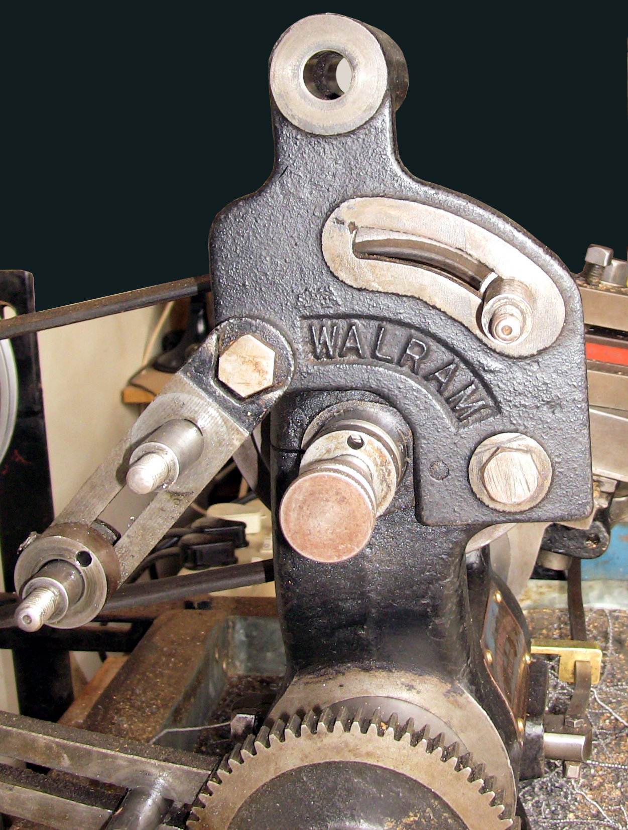
To connect the gears in pairs for a compound train, each gear carried a pin and a pin hole (a useful tip is to know that the pins are pressed into tapered holes and, if driven out the wrong way, will fracture the gear). By combining extra changewheels a large number of odd pitches and metric threads could also be cut - however, one serious drawback with the lathe was its lack of slow speeds to help with screwcutting and large facing jobs; no backgear was fitted and the bottom speed with the maker's countershaft was approximately 120 r.p.m. Although it is known that Drummond made at least one Round Bed with a cast-in backgear carrier, it was not a production version (and carried no serial number) and owners were either compelled to attempt re-jigging of the belt drive to give lower ratios, making their own gear-reduction system or, more effectively, by resorting to a number of third-party accessory suppliers who offered two types of solution: the ingenious Walram - or some form of proper backgear. The (now very rare) Walram bolted in place on the end of the headstock casting using the reversing stud bracket as one of its mounting points. Its ingenious design provided three main features: a means of driving the headstock spindle through gears (either faster or slower than normal); an ultra-fine carriage feed to be set up and the ability to generate left-hand threads. The backgears systems offered were either of a conventional design - with supporting arms that clamped around the bed to carry gears at the back to mesh with those fitted to the spindle and spindle pulley - or rather splendid epicyclic mechanisms built into a slightly larger-than-standard headstock pulley. At least two types of the latter were offered: the first, by George Gentry, being published in the "Model Engineer" magazine during 1912 and the second, by A. E. Bowyer-Lowe complete with illustrations and detailed drawings, in the same magazine for April 1st, 1915. Perhaps best known of the clamp-on backgear makers was W. H. Bass of 144 Burleigh Road, Enfield in Middlesex. This engineering firm not offered a number of accessories designed to overcame deficiencies in the standard machine - a hollow mandrel in 35-ton tensile steel, a backgear system and even a tumble-reverse mechanism - but also some unexpected items including a 6-station capstan turret, a cut-off slide and a T-slotted boring table. The items designs were reviewed in Model Engineering Magazine on September 11th, 1919 and February 5th, 1920.
Drummond offered only a very limited range of accessories; there was no fixed or travelling steady, special toolposts, milling slides or boring tables. However, al though the basics were neglected, they did offer the more ambitious enthusiast a neat and effective Indexing and Gear-Cutting Attachment that mounted on the supplied-as-standard angle plate and swivelling adapter (with a graduated base) - the latter an item that must have been either very popular as an accessory, or later supplied as standard, for many used machines come with one in their stock of kit.
Over the years various drive arrangements were available including the usual type of fixed and fast-and-loose countershafts for wall and ceiling mounting - but the most popular and common arrangement was a pair of legs and a chip tray (all in cast iron) fitted with a 100 lb flywheel running on a plain bearing and with operation by treadle.
Though of simple design and construction the Round-bed Drummond was, in sympathetic hands, capable of accurate work and many examples are still in use today. In standard short-bed form its overall length was 2 feet 11 inches (889 mm) and the basic machine weighed approximately 105 lbs. (48 kg).
Colour: the writer is often asked what the original colour was. Evidence from removing the maker's badge from an early (detachable headstock bearings) models shows this to have been a very dark shade of blue - almost a black. On exposed surfaces over many years this original paint would have oxidized to a an even darker shade, so giving the impression that the lathes were, indeed, painted black.
Machines with an "A" prefix are pre 1920 - afterwards "0" was used. However, on some machines this is missing - while others have no Serial number. If there, the number will be found stamped into the section of bed that protrudes from the left-hand-face of the headstock (it can be made out in the picture immediately below).
Yearly figures from the introduction in 1908 to 1912 are not known - but thereafter factory records show that:
From 05/07/13 to the end of 1914 Serials 5300 to 6175
1914 to 1915 Serials 6176 to 6379 1915 to 1917 Serials 6380 to 6515
1917 to 1919 Serials 6516 to 6719
The above figures suggest that just 543 examples of the Round Bed were made during WW1.
Starting with a new numbering system, the next set of record began with the prefix "0". However, although Company ledgers record the "0", research shows that it was not stamped on every machine; some have, some do not.
1919 Serial numbers to 0680 (the start number is not known, but might have been 0101)
1920 to 1923 Serials 0681 to 02144 1923 to 1924 Serials 03398 to 03991
1924 to 1926 Serials 03992 to 04585 1926 to 1928 Serials 04586 to 04981
1928 to 1930 Serials 04982 to 05377 1930 to 1932 Serials 05378 to 05641
1932 to 1935 Serials 05642 to 05905 1935 to 1938 Serials 05906 to 06103
1938 to 1943 Serials 06104 to 06193
The very last Round Bed was sent to Myford on May 18th, 1943.
Production from 1908 to 1913 around 1500 - and the grand total, to 1943, about 9253..
More Drummond Round-bed here
|
|
|
|
|
|
|
|
|
|
|
|
|
|
|
|
 |
|
|
|
|
|
|
|
|
|
Machine Number clearly stamped - though some |(perhaps with a replacement bed) are found without. In 1919/20, Serial number prefix changed from "MCH.A." to "O" - though some lack the "O"
|
|
|
|
|
|
|
|
|
|
 |
|
|
|
|
|
 |
|
|
|
|
|
|
|
|
|
Rear of the carriage showing, at the bottom the slot that allows the saddle to be rotated around the bed. Just visible in the slot is the wedge that clamps the assembly tight
|
|
|
|
|
|
|
|
|
|
|
|
|
|
|
|
 |
|
|
|
|
|
|
A fine original Round Bed on the maker's treadle stand
|
|
|
|
|
|
|
|
 |
|
|
|
|
|
|
Above and left: the second type of headstock bearing was simplified and made in one piece with a slot across the back for adjustment. The bolt at the front threaded into the headstock casting while at the back two small screws held down the other side.
This lathe is carrying the rare bolt-on arm to carry the extra changewheel necessary to generate left-hand threads.
|
|
|
|
|
|
 |
|
|
|
|
|
|
|
|
|
|
|
|
|
|
|
 |
|
|
|
|
|
|
The Milling Slide (in essence a spare top slide) shown mounted on the adapter unit and carrying the Drummond Gear Cutting Indexing Unit - which used the lathe's standard changewheels. This is a heavily-retouched publicity picture - witness the absence of T slots in the saddle.
|
|
|
|
|
|
|
|
|
|
|
 |
|
|
|
|
|
|
|
|
|
Very seldom found: the fixed and travelling steadies for a Drummond Round Bed
|
|
|
|
|
|
|
|
|
|
|
|
|
|
|
|
 |
|
|
|
|
|
|
The ultimate big boring job!
|
|
|
|
|
|
|
|
 |
|
|
|
|
|
|
Backgear Type 2 - full-width clamp-on style with a split-bolt split clamp on the bed and a bolt-on spindle to carry the gear (see this page for the Type 1 backgear)
One serious drawback to the Round-bed Drummond was a lack of low speeds, usually achieved on other lathes of the same size by a backgear assembly. Although Drummond never offered such a fitting on the British market - but the Australian version of the lathe was sometimes so equipped - the writer has identified six third-party suppliers of bolt-on conversions. However, only one, the Walram, has been positively identified - so the others, being unrecognised, we shall call the Types 1, 2, 3, 4 and 5. Other conversions, marketed pre-WW2, used a train of epicyclic gears built into the largest diameter of the headstock pulley - on the lines of a system incorporated in the American "AA Products" lathe sold by Sears under their Craftsman label as the Model AA109. For the Drummond at least two such designs were developed: the first, by George Gentry, being published in the "Model Engineer" magazine during 1912 and the second, by A. E. Bowyer-Lowe complete with illustrations and drawings with sufficient detail to enable home construction, in the same magazine on April 1st, 1915. In addition, several sets of drawings for conventional systems were published for home-built building and examples of these do turn up from time to time - as do obviously home-made (and often crude) constructions. Of all types, the Walram was the most ingenious and well-thought-out system and, in addition to being marketed for the Round Bed, may well have been offered for other makes as well. The device bolted to the end of the headstock casting and was driven from the normal countershaft by flat belt. The unit, which allowed the spindle to be driven through either reduction or step-up gearing, also provided a means of powering the leadscrew and would have been able to generate an ultra-fine carriage feed. The latter was achieved by means of an additional compounded gear train where two gear, one large and one small, were pinned together on a common shaft. Normally the Round Bed (like most other lathes) would have been able to accommodate only two compounds but, with the Walram in place, three could be assembled. For example: with gears sets of 21/40, 20/63 and 20/64 in place a feed rate equal to 192 T.P.I. could be generated, far finer than that available with the standard set-up As the Walram employed the left-hand threading bracket as part of its mounting it could also be used to generate left-hand pitches and so was able to be left in place for all normal work..
The more conventional backgear systems were also ingenious and well-engineered jobs with the Type 1 being fitted to the very first version of the Round Bed with bolt-on spindle bearings. With the introduction of the headstock with the spindle running directly in the cast iron of a one-piece casting, the backgear designer took advantage of the separate bearing housings and made new, one-piece bearings with an extension at the back of each to carry the backgear shaft. Although this arrangement did away with the separate bearing caps (an illustration of the original design is below) the new units would, presumably, have had some means of setting the bearing clearance…. or perhaps not. In addition to the new bearings it was also necessary, in order to make room for the backgears, to replace the original 3-step flat-belt pulley with a 2-step of considerably narrower proportions (though it only surviving example so far seen it appears that a previous owner has modified this to take either a round rope or narrow V-belt.
The Type 2 backgear was carried, neatly, on a single casting that clamped round the bed to the left of the headstock, the unit using a bolt-through overhung shaft retained by a nut. Unfortunately, the amount of space left between the gears (they were the same pitch as the ordinary changewheels) allowed only sufficient space for a 2-step flat-belt pulley.
A rather more complex and expensive-to-produce affair, the Type 3 backgear, was held on with two bed clamps, each carrying a separate bolt-on and tennoned bearing housing. Being made during the 1930s, this conversion avoided the reduction in the number of speeds on the flat-belt-drive version by using one of the newly-available Z-section, 3-step V-belt pulleys.
Very similar to the Type 1, the Type 4 differed only in having the backgear spindle retained by a press fit in the support casting. Simplest of all was the Type 5, this, possibly, being by W.H. Bass of Enfield and similar to the other third-party offerings but of a more economical unit and carried on a bed-mount held in place by a crude through bolt (a copy of the W.H. Bass advertisement is reproduced at the bottom of the page). It was fitted with a through-shaft fitted with a small gear on its outer end and a larger one on the inner - the latter engaging with a small gear on the spindle (positioned between the pulley and left-hand bearing) while the small gear meshed with a standard changewheel mounted on the end of the headstock spindle. Recently discovered (2020) is a backgear, Type 6, that incorporated a 3-step V-belt drive pulley, V-belts having come into increasing use during the 1930s on small lathes.
Unfortunately, though a most useful fitting, backgear is not always the answer to a maiden's prayer for, with the huge increase in torque available, the saddle can sometimes be forced around the bed, the single clamping bolt producing insufficient grip to keep it in place.
Should any reader have an example of a backgear system fitted to a Drummond Round bed the writer would be interested to hear from you..
|
|
|
|
|
|
|
|
|
|
|
|
|
|
 |
|
|
|
|
|
|
Another view of the full-width clamp-on Backgear Type 2
|
|
|
|
|
|
|
|
 |
|
|
|
|
|
|
The smaller gear of the Type 2 backgear was overhung on the end of the bolt-through spindle
|
|
|
|
|
|
|
|
|
|
|
|
|
|
|
|