|
Home Machine Tool Archive Machine-tools for Sale & Wanted Books Accessories Drummond - Rare 4" Flat-bed Lathe Literature for Drummond lathes, gear shapers and other machine tools is available |
Quite how this (and a few other examples) of a very unusual Drummond 4-inch lathe ended up in Australia is not clear - but it is known that the more active of the two Drummond brothers, Arthur, visited the continent in the early years of the 20th century and was involved, whilst there, with the design of a lathe headstock with a spindle large enough to pass the pipes used to pump water out of the many wells then in existence. It is entirely possible that amongst his luggage were proposed designs for various new designs including improvements to existing models (such as the unusual backgeared Round Bed) and it may well be that a limited number of lathes were built for him by sub contractors. Bearing many similarities to its smaller contemporary, the first version of the 31/2-inch B Type, from the detail changes made to this smaller lathe and assuming that the 4-inch followed a similar evolutionary pattern, the machine is certainly of pre-1906 origin, and possibly even pre-1903.
Although no maker's address is present on the lathe, a contemporary model has plate inscribed Wood Street, near Guildford, Surrey - the first published address the Company that also appeared on their first production lathe (the usual references showing them first advertising from Pinks Hill, then Rise Hill before finally settling at Rydes Hill at some point before 1906.
Should any reader have one of these rare Drummond lathes - they have, so far, only been found in Australia - the writer would be pleased to hear from you..
|
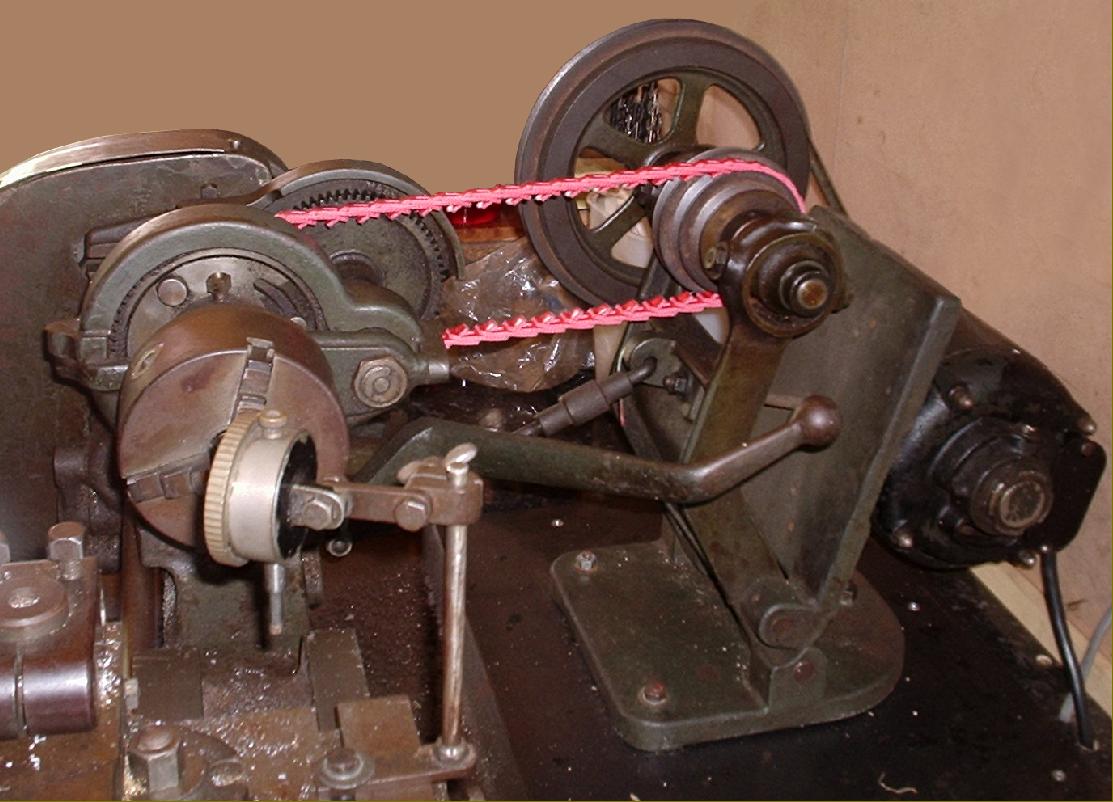
Of approximately 4" centre height and admitting 20" between centres, the Drummond "4-inch" featured a heavy "beading" around the edges of the bed - a distinctive feature of early Drummond - and some other contemporary lathes - and must have been designed to add some stiffness to the very elegant if rather light casting. Also of assistance in stiffening the structure was a heavy cast-iron chip tray with cut-outs at front and back to give clearance for the round-rope belt. The original drive would have been from a foot-operated treadle and flywheel assembly, almost certainly of the type used on the 3.5-inch flat bed. The layout of the screwcutting arrangements was identical to those on a Mk 1 B Type: a "power shaft", with a dog clutch at the headstock end, ran the length of the bed and engaged a gear at the tailstock end to transmit its drive upwards to the leadscrew that lay between the lathe bed ways. With the leadscrew running directly under the carriage and connected to it by a full nut, forces from the toolpost were able to follow the most direct and least flexible path. |
|
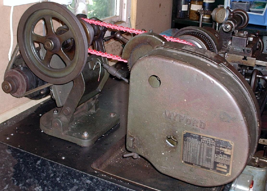
pulley originally intended to accept a round "gut" leather-belt. |
|
|
||
|
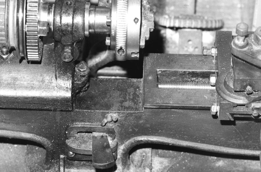
The leadscrew dog-clutch operating handle protrudes through the bed immediately below the gap. Underneath is an unnecessary bolt-on support plate - removed from the smaller "B-type" lathe in 1907. |
||

|
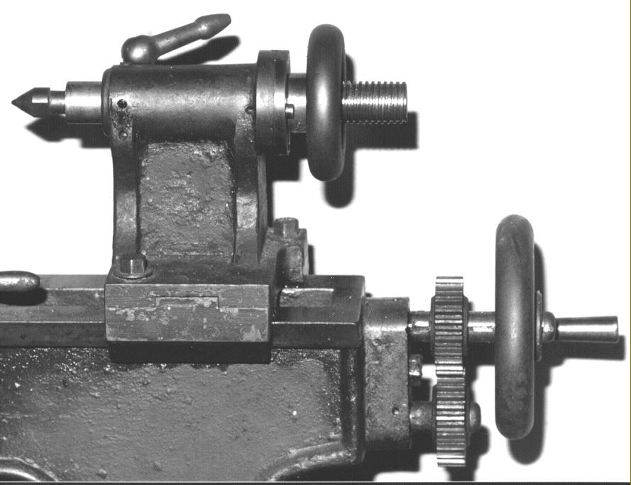
The tailstock and leadscrew-drive gears are almost identical in shape to the smaller machine. Instead of a crude bolt bearing down directly onto the tailstock barrel to lock it, it appears that a change has been made to a slit in the back of the casting closed down by a through bolt fitted with a handle. |

|
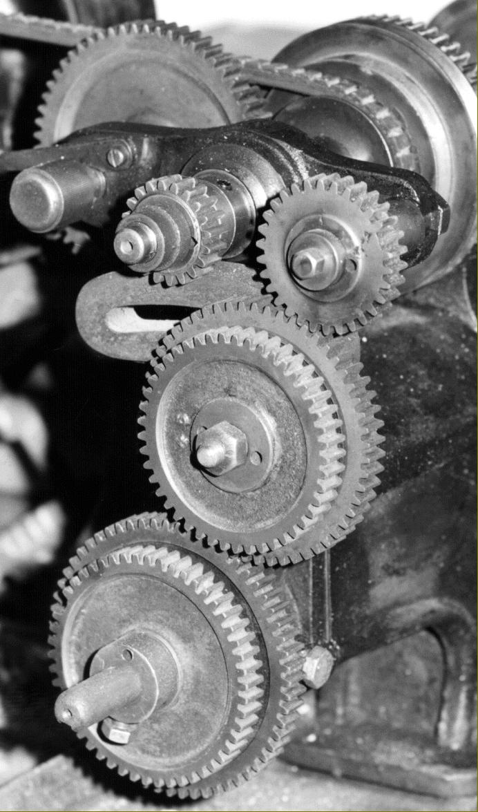
The changewheels are mounted on an L-shaped bracket - with an additional slotted bracket on the headstock to carry the stud and gear necessary to cut left-hand threads. The screwed gear-retaining ring on the end of the spindle has been put on the wrong way round. |
|
Home Machine Tool Archive Machine-tools for Sale & Wanted Books Accessories |
||