|
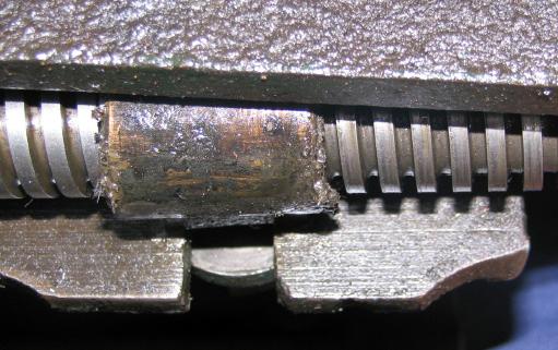
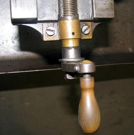
With B-Type production having stopped during 1919, Drummond began work on a pilot batch of a new model during 1919-1920 - these lathes carrying Serial numbers from 1 to around 131. With production arrangements made, in 1921 Drummond were again ready to launch an improved version of their smallest lathe, this time designated as the M-Type. However, this first version, to be heavily revised in in late 1924, was to have the shortest run of any model (save perhaps the original produced in 1902 and first modified in 1904). The aim of the new alterations was to improved rigidity and resistance to tool chatter and the main changes focused on the headstock where a greater mass of metal was used, the futile over-arm brace removed and the flexible and poorly supported system of using two flat surfaces simply bolted together (by which means the headstock could be rotated slightly) was abandoned. In its place was a positive location with a tongue on the base of the headstock located against a matching vertical surface on the bed - the whole assembly clamped down firmly with four bolts. Larger spindle bearings were employed, the adjustment of which reverted to an earlier Drummond design where a large ring, screwed onto the end of the bearing itself, pulled it into the tapered headstock housing and provided a means of accurately adjusting the clearance. The design was actually more complex than at first appeared and required careful manipulation of a "drilled oil bolt" that acted, via a wedge, to expand the bearing fully into its housing. As a final touch, a proper ball-bearing thrust race was engineered to fit against the inside left-hand end of the spindle. As an aid to heavier rates of metal removal, a long-needed, three-step flat-belt drive replaced the by-now hopelessly inadequate small-diameter round "gut" drive previously used . The spindle nose was again, as in 1912, upgraded and fitted with a 1" x 12 t.p.i. thread backed by a 11/8" register designed to improve the rigidity of screwed attachments. The backgear ratio was changed from 20:60T to 22:66T and engaged by rotating an eccentric shaft instead of sliding into place. In place of having to reach for a spanner to disengage the 66t bull wheel from its embrace with the belt pulley, a cleverly designed "ramp" (that acted as a cam) was machined into a plate on the front of the gear. If everything was adjusted to slide easily, a swift push by a gnarled thumb against a knurled-edge knob was sufficient to persuaded the close-fitting engagement pin out of mesh with the pulley-flange. To engage direct drive the backgear was swung away and the knob merely moved slightly in the other direction - when a spring on the pin returned it automatically to engage with the pulley. The writer spent some time using one of the lathes and the speed with which backgear could be engaged and disengaged was a delight. The No. 1 Morse taper tailstock was also further increased in strength and the barrel diameter increased from 3/4" to 7/8". The previous rather crude screw-in barrel clamp gave way to a much more elegant and efficient "cotter" or "internally-split" locking device and some machines (but not, surprisingly, all) were given a hollow barrel to solve the problem of how to remove centres and chucks. |
|
|
|
|
|
|
||