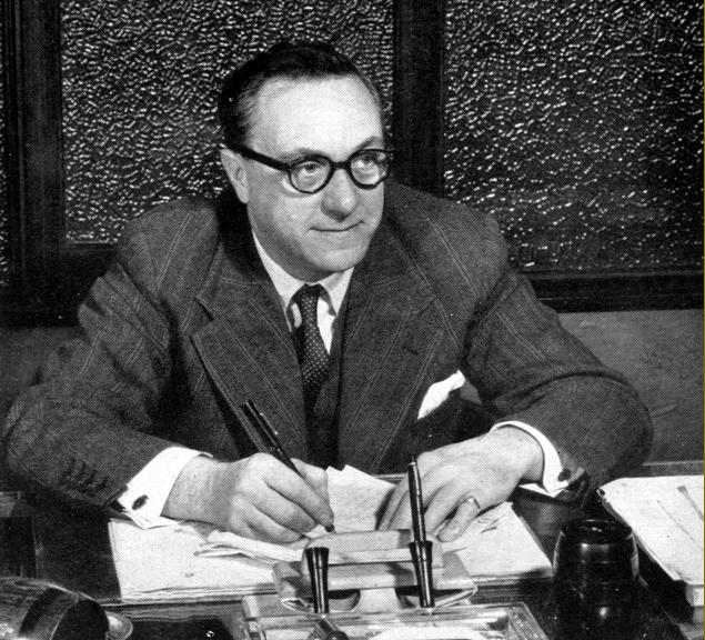
email: tony@lathes.co.uk
Home   Machine Tool Archive   Machine-tools for Sale & Wanted
Manuals   Machine Tool Catalogues   Belts   Books   Accessories

Boxford Lathes
Belt-drive 4.5" and 5" Models
Thinking of buying a Boxford or new to the make?
Scrolling down and reading this page will pay dividends
Do you have an unusual Boxford of non-standard specification?
If so, the writer would be pleased to hear from you


Spare Parts For Sale 

Boxford Models A, B, C, AUD, BUD & CUD   Boxford Lathe Accessories 

Model ME10     Boxford VSL & 500 Vari-Speed   

Model T & TUD Training Lathes    Model CSB

Miniature Precision Boxford Lathes    Larger Plain-turning Precision Boxford

Late Model Geared-head Boxfords   AUD Photo Essay 

Serial Numbers     Screwcutting Gearbox   Screwcutting Calculator - all models   

Power-feed Apron Models A and B

Boxford Accessories    Little Giant Tool Post Grinder    Taper Turning Attachment

Drive Systems   A Rare gap-bed Boxford

Boxford Precision Inspection Tools   Other South Bend Clones
 
Boxford Miller   Boxford Shaper   Boxford and "Union" Drills   Boxford  Tool & Cutter Grinder   

Boxford Catalogue Covers    Boxford Price Lists


A detailed Manual & Parts List  is available for all Boxford lathes

We also manufacture and supply changewheels and many other spares including

beltsthread-dial indicators, faceplates & other parts


Well made, strongly built and capable of sustained hard work, the original belt-drive Boxford lathe has long been a favourite with not only amateur and professional engineers, but also schools and colleges where many thousand were installed during the 1950s and 1960s. The lathe had its origins in the Denford Small Tools Company (D.S.T.), founded in Brighouse by one Horace Denford in the years before World War Two. The company's original products included a range of precision tools and inspection equipment - and, no doubt, sub-contract work for the many local general-engineering and machine-tool companies who once inhabited the area. It is believed that Denford moved at least part of their operation to a former spinning factory, Box Tree Mills, in Wheatley, Halifax during the closing years of WW2 (1939-45). The previous occupants had been a ship's telephone equipment manufacturer, Arthur Graham Ltd., who used the building between 1942 and 1944 after being bombed out of their Woolwich (London) premises.
Having set up in Wheatley, a new company was formed, "Denford Machine Tools" and, in 1946, production began of various precision products including the well-known "comparator" (together with its different holding stands) parallels, straight edges, sine centres, sine tables and, most important of all, two small bench lathes. All items were branded "
BoxFord", including the lathes, one of which was a precision plain-turning type (intended to compete in the same section of the market as the Schaublin 65 and 70), and the other, of a similar size but almost completely different construction, a miniature capstan. With supplies of such machines yet to be available again from the German factories of G.Boley, Lorch and Leinen, and with Schaublin in Switzerland no doubt running flat-out to meet outstanding orders, the lathes were priced at an astonishingly high £175 (when a backgeared and screwcutting ML7 was around £60 and a 5-inch Raglan with screwcutting gearbox £144). Nevertheless, demand in the UK was such that the factory hinted at a production run of over 400 units. Even today, in confirmation of these numbers, a small but regular supply of these well-made little machines turns up on the second-hand market. As a point of interest, these were not the only Boxford precision lathes for another type, a considerably larger 4.5" x 17" machine, was built in small numbers from 1958 until the early 1960s. Other machine tools made included a useful little shaper (copied from a South Bend original), a tool and cutter grinder (also sold under the Union and Harrison names) and a variable-speed vertical milling machine.
Continued below:

The first Boxford Model A: flat-belt drive, screwcutting gearbox, power cross feed
and quick-release countershaft as made from April 1948 to January 1951

Continued:
Following the two early precision lathes, the company's next model, introduced in 1948 and again branded a "
Box-Ford", was an improved copy of the Pre-WW2 American South Bend  "9-inch Workshop" model, a type that dated back to the last months of 1933 and the Company's Model 5.  The earliest known publicity material concerning the new 9-inch model is a typed sheet found pinned to a pair of 1947 catalogues for the small precision lathes (it's reproduced at the bottom of the page). Details included are scant, just the main dimenions and specification and no hint of a Model Type or Series Nnumber. To date, the earliest catalogue found is a well-produced folder with a cream-coloured cover in card holding twelve sheets (secured with split pins) showing all three models, A, B and C, together with a range of accessories. Other catalogue covers can be seen here.
By the 1970s Boxford had started to introduce a number of training-type CNC lathes and milling machines, a successful path that they follow to this day. In addition, a replacement for the original belt-driven 4.5-inch was announced, a geared-headstock model produced in various versions for both training and industrial use.
Denford was not the only company to clone the South Bend, the simplicity and ruggedness of the design also appealing to many other makers including Hercus, Sheraton and Purcell in Australia (the Purcell was also introduced in 1948); Blomqvist and Storebro in Sweden; Sanches Blanes and Joinville in Brazil; Boffelli & Finazzi in Argentina, Smart and Brown and Ace in England, Stirebro in Sweden, "Select" in Taiwan, NSTG in the USA and Moody in Canada. However, apart from Hercus, none of them enjoyed as great a success as Boxford and the new lathe was, in its various forms, to be the foundation of the Company's success. In 1952 Mr. Denford sold out the Box-Ford part of his enterprise to T.S. Harrison & Sons Ltd. and transferred his other operations, still under the D.S.T. banner, to the Brighouse site they occupy today. Although Harrison owned Boxford, only export versions of the lathe ever carried a dual Harrison-Boxford badge - oddly, even into the 1960s and the Mk. 2 models when fresher, more modern labels had been introduced, the Boxford name on these machines was still styled in the original "block-lettered"
Box-Ford style. Harrison eventually sold the Boxford concern, the last machine made under their ownership being Serial 284500 in early 1971.
Shortly after the change of site, Mr. Denford made moves to compete more strongly in the education and training market and introduced his "Viceroy" lathe, a machine very similar in general layout to the Boxford but of stouter build, with a heavy-duty, near-indestructible No. 3 Morse taper tailstock and mounted on a safe, completely-enclosed under-drive stand. This lathe would, in the years to come, provide stiff competition for Boxford. The Company also widened their range of products to include wood lathes, tool-sharpening equipment, floor-standing double-ended grinders and polishers and a number of re-branded machines including pillar and bench drills, a drill-sharpening machine, a shaper (actually made by Realm Engineering of Croydon, Surrey and also sold as the Royal) and a milling made by AEW.
In 1962 Gerald Denford, the son of Horace, took over from his father and developed the move to CNC technology. On his death, in 1987, he was succeeded in turn by his son, Andrew, as Chief Executive with his daughter, Nicola, as Corporate Affairs Director

The Belt-drive Lathes:
With the exception of the headstock (and its location on the bed ways) the new 4.5" x 21" Box-Ford (though the actual centre height was 4 5/8") was almost an exact copy of the South Bend original and available from launch in the same three versions: a top-of-the-range "Model A" (£132) with screwcutting gearbox and power cross feed, a "Model B" (£116) that retained the power cross feed but with screwcutting by changewheels and a basic "Model C" (£89) with changewheels and hand-operated cross feed. Even though the South Bend headstock, together with its spindle and plain bearings, had proved to be reliable and rugged (a South Bend bed always wears out before the headstock) Boxford used a much more rigid, box-like casting open only at the rear (to accommodate the drive belt) and carrying a spindle running in easily-changed taper roller bearings. Instead of locating the headstock on a front V and rear flat as South Bend had done, Boxford choose to use a V-way at both locations. However, in later years, with the development of under-driven versions (with a belt running down the front face of a now wider headstock) a change was forced back to the original layout. Even so, on these machines, to keep things looking "right" when viewed from the front, a deep dummy V was cut into the underside of the headstock casting.  Beds until the advent of the Mk. 2 Underdrive were unhardened, after that this option was offered - though this desirable feature can rarely have been specified, the writer having never encountered one
The main dimensions of the original South Bend spindle, with its 1.5" x 8 t.p.i. nose, were unchanged, and indeed stayed the same on the ordinary V-belt drive Boxfords until the end of production. An interesting note in the Company's records states that:
From Serial 1360 all machines have an 8 t.p.i. Whitworth form spindle nose - a reference to the fact that the first batch must have had an exact copy of the South Bend fitting with its American 60° thread angle (the Whitworth is 55°). Behind the change to roller bearings would have been an intention to not only improve the lathe, but also to gain economies of production where the spindle, instead of being hardened and "micro-finished" to run in the cast-iron of the headstock, could be made to lower tolerances in a less-expensive material. A further advantage was that the bearings could be replaced easily and, if required, much higher spindle speeds reached with reliability. Although roller bearings might have been chosen as a more-easily engineered solution, Denford chose, on early models, to use a more expensive type having 14 rollers and marked "Precision 5" (with inner and outer races coded 2720 and 2788 respectively). Later models had ordinary bearings with 17 rollers and a shallower cone angle - and seemed to have worked just as well.
Continued below:


Mr. Horace Denford

Continued:
4.5-inch and 5-inch centre height lathes - an overview:
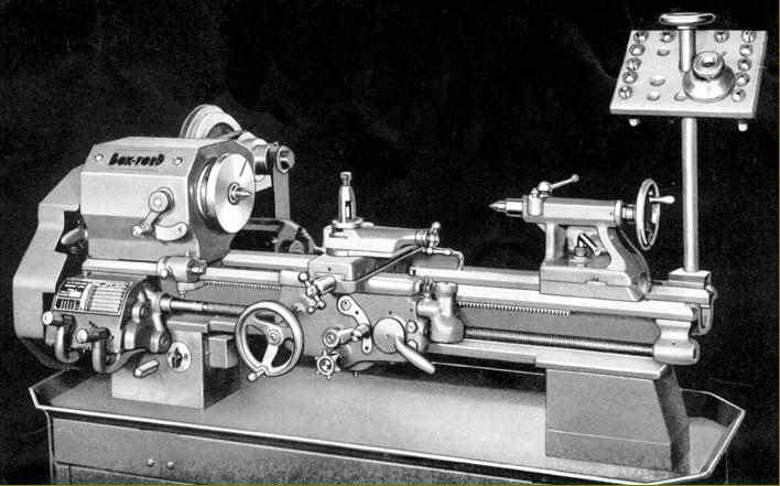
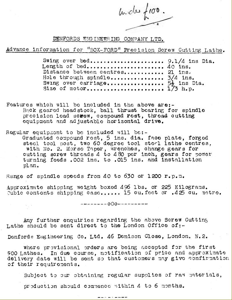
With serial numbers starting at 1001, the first batch of  "9-inch" lathes left the company's Box-Trees factory during April, 1948. These first machines (stamped with a DEH prefix to their serial numbers standing for, presumably Denford Engineering Halifax) were basic machines with screwcutting by changewheels and hand cross feed; they were fitted with a 3-step flat-belt drive to the headstock, no countershaft or headstock belt guards and with the motor on/off switch built into the front face of the headstock-end bed foot. The countershaft assembly - built as part of the lathe so making it a self-contained unit, ready to run - was carried neatly on two bars passing through bosses cast into the back of the headstock-end foot. Control was by a lever protruding through the foot's front face, a "quick-thread" mechanism being provided to slacken and tighten the belt. Bored through 0.75" (on all models save for the later VSL with its L00 nose) the spindle, as mentioned before, ran in expensive "precision" Timken taper roller bearings (though cheaper but just as effective standard ones were to be used in later years). Collets by Crawford, sized at C3, were carried in a hardened nose insert and retained by the usual sort of threaded draw-tube.
Exactly when the gearbox and power cross-feed models were first made is uncertain, but they must have followed within a few months, for South Bend had been offering these versions since 1939 and the first known properly printed and illustrated advertising literature does show all three types.
On the very first examples made the lathe was clamped to the stand or bench by two in-line bolts that passed upwards into each bed foot - the latter having been found cast in both cast aluminium and iron. The next version used three securing bolts, two being set across the bed and passing through a flange on the inner face of the (now exclusively cast-iron) foot and with the other on the foot's centre line passing through an inwards-facing boss. The final type, and found on most machines today, was a simpler arrangement of two bolts - one at the front and the other at the back of each foot. When fitted with the optional 2-step pulleys on motor and countershaft, and combined with the 3-step cone (flat-belt) headstock pulley, these early versions had a usefully wide spread of spindle speeds (though bottom speed was too high) of approximately: 76, 140, 250, 390, 710 and 1300 in open belt drive and 40, 67, 120, 190, 350, 640 in backgear. The backgears, though often found damaged on used machines by mishandling, were robust enough to allow the lathe to be easily capable of turning the largest faceplate-mounted job. Both slides of the compound rest were driven by 10 t.p.i Acme-form (or 2.5-mm pitch) screws fitted with 1.6-inch diameter, satin-chrome zeroing micrometer dials - the friction setting of which could be adjusted (or locked) by a pair of by socket-headed screws that bore against spring-loaded balls.
In January 1950 the flat-belt drive was abandoned, with lathe No. 1791 to become the first fitted with 4-step V-belt drive - a much-improved arrangement that gave a more useful bottom speed (ideal for screwcutting by beginners) and a total of 16 rather than 12 speeds. To convert a flat-belt machine to V-belt specification is simple - the pulleys interchange without any modifications being required. The standard V-belt speed range ran from 38 through 55, 87, 125, 75, 110, 175 and 250 r.p.m. in backgear and 200, 285, 450, 650, 400, 570, 900 and 1300 r.p.m. in direct (belt) drive. According to Work's literature seen by the writer, at the same time the tumble-reverse mechanism was altered: the inconvenient and slow-to-change bolted-up arrangement being replaced by a simple, quick-action, spring-loaded plunger design (though it's a fair bet that the change was not immediate and some lathes might have had the old parts fitted).
One unusual, possibly unique model, probably constructed during 1949/50, was a gap-bed model of which just two examples are known, both currently in South Africa. Using otherwise standard parts - headstock, carriage assembly and tailstock, it was built as a Model A and might have been inspired by South Bend's almost simultaneous introduction of a similar type (the Boxford being based, of course, on the South Bend "9-inch") or possibly prototype machines taken to South Africa by an ex-employee. they might even have been part of a small batch built to a specification required by an importer or Government agency; however, it's almost certain that their origins will remain forever a mystery.
In 1951 a very slightly cheaper version of the ordinary Boxford was introduced, the 4.5" x 16" Model CSB. Unlike the £112 Model C, which lacked a motor in the basic price, the CSB was delivered complete and ready-to-run (with a just-about-adequate 1/3 h.p. motor) for £105 - a total saving of some £16 : 5s : 0d. Other prices in 1951 were: Model A £170 (22" centres) and Model B £142 (22" centres) with an extra £8 and £9 respectively charged for the long-bed with 28" between centres (by 1955 prices had risen to £185, £155 and £125 for the A, B and C respectively). The rear-drive lathes remained in this new V-belt drive form until 1959 and the introduction, from approximately Machine No. 8755, of the "Underdrive" type that had a range of 10-speeds. Made from welded steel plate, the new stand held the countershaft and motor assembly, the optional coolant tank and motor and provided, in its right-hand compartment, storage shelves with a collet tray fastened to the inside of the (locking) door. The door locks, incidentally, were those used on the glove boxed of various Triumph car including the Herald and Vitesse - hence dealers in classic Triumph parts can supply new ones - a supplier in 2022 being Rimmer Brothers and the part numbers being 611584 for the lock and 609463 for the "finger pull".
Belt tension was released by an external handle that protruded through the stand's left-hand face, a fitting that provided a strong temptation to use it as a clutch - a potentially dangerous undertaking. This weakness (from a safety point of view) was removed when the mechanism was redesigned and made accessible only by opening the door. The new lathes were sold as "AUD", "BUD", "CUD" and "TUD" models (with the "UD" suffix standing for "under-drive", of course) and "A", "B" and "C" reflecting, as before, the specification. However, the new models did not replace the old, but complimented them, the original rear-drive types remaining in the Boxford catalogue (optimistically, one would have imagined)  until at least 1977. With the introduction of the Under-drive models came a superior cosmetic finish with the castings carefully fettled, filled with cellulose knifing putty, rubbed down by hand and spray painted. While not to the standard of the very much more expensive Raglan lathe, with its use of special Trimite paints, this new finish (generally in a grey cellulose to BS692 sprayed over a filler) was a considerable improvement over the earlier lathes, the first of which had, to be blunt, a decidedly utilitarian appearance.
Although the rear-drive models suffered from a very deep countershaft, and consequently took up a good deal of room, the under-drive versions were very compact - with a bare stand only 17 inches front to back - and today are consequently by far the more popular buy second-hand.
From December 1973 - approximately Serial No. 33000 - the swing was increased to 10 inches, but with the rear-drive lathes remaining at 9 inches. The distance between centres offered varied over the years: at first all types were offered with 16", 22" or 28" - the latter being very rare.  Later, only the two longer beds were offered, the 16" option being consigned to the cheaper CSB model. All Boxfords were "straight bed", that is, none of them, unlike some models of the South Bend 9-inch of the early 1950s, had a gap. Besides the conventional V-belt drive already described, the lathe was also marketed as the comparatively rare VSL with expanding and contracting pulleys giving a useful mechanically-operated variable-speed drive system.
Later Under-drive lathes of all versions enjoyed a number of refinements and are known as the "Mk 2 Under-drive". They were built with a 4.5-inch centre height from the 1st of December 1963 (probably serial number 11-13513) and from December 1973 (around Serial No. 11-33000) as a 5-inch model (the "11" prefix indicated the Mk. 2, earlier models generally had no such stamping though the prefix "10" has been seen on some examples and on some a suffix "5", these indicating, in the latter case, a lathe with a 5-inch centre height and in the former with a 10-inch swing--both of course being the same). The main improvements centred on increasing operator safety and ease of use: backgear no longer need two levers to be engaged, instead the initial movement of a single, electrically-interlocked lever on top of the headstock released the bull-wheel from the spindle pulley and the final push sliding the gears into engagement. On early versions the large headstock gear was left "as cut" but later models (from an unknown date) had the leading edge of the teeth rounded to ease engagement. A useful addition was a spindle lock, operated by a dished chrome-plated button on the face of the headstock; this greatly eased the removal and fitting of chucks and faceplates and obviated the need to use, and possibly damage, the backgears. At the same time the opportunity was taken to reposition the various headstock oil nipples so they could be reached without having to open or remove any covers - a hole being drilled through the front face of the headstock (on the sloping surface) so that an oil can could be used to lubricate the spindle-to pulley bearing before engaging backgear. To give a stronger assembly and quieter running, the pressure angle of the backgears, the tumble-reverse gears and the drive gear on the end of the headstock spindle was changed from 14.5° to 20° - although the changewheels themselves (from the first lathe made to the last) remained unaltered. The top slide was provided with an extra 3/8" of movement (that usefully increased it to the same length as a No. 2 Morse taper) and both top and cross-slide feed-screws (actually from Machine No. 12419 in January, 1963) fitted with ball-bearing thrust assemblies, the inner and outer hardened plates of which, over time, can become indented and give the action a "gritty" feel.. The micrometer dials were satin-chrome plated and fitted with an improved friction "clutch" that did away with the need to lock the setting with an Allen key, while the degree-indexing marks (to indicate top-slide swivel) were moved to an angled surface in an effort to make them easier to read. Unfortunately, the rather awkward (not to say crude) method of adjusting the position of the micrometer dial on the cross-slide screw, involving a grub screw through the handle into a dimple on the shaft, was not changed. Captive nuts were fitted to the underside of the motor-mounting plate so that adjusting the belt tension on the primary-drive involved no more than slackening the clamping bolts and sliding the motor into the correct position; the countershaft spindle was increased in diameter, fitted with sealed-for-life deep-groove ball races and the motor-end cabinet door louvered to improve cooling. To improve lubrication of the countershaft bearings - and avoid having to open the door to do this - the end of the countershaft was arranged to protrude through the left-hand face of the stand so that oil could be injected by the direct application of a pressure gun.  Electrical interlocks, by micro-switch, were fitted as standard to the backgear lever, changewheel guard and motor-cabinet door - but these could, if not required, be eliminated from the specification of a new machine and the price reduced by £1 : 10s : 0d (£1.50) for each unit left off (to disable the electrical locks on your own Boxford it's possible to bridge their contacts on the terminal block fitted at the rear of the headstock-end bed foot). To improve the appearance of the lathe some small but significant improvements were made to the fit and finish of various components including more precise mating of the headstock-to-changewheel guard and bed-to-screwcutting gearbox faces. The appearance of the tailstock was also cleaned up and, as a final touch, a modified catch - though still largely useless and easily-opened - was fitted to the changewheel guard. For the first time Boxford offered as an option what they described as "chrome hardened" beds - though few such can have been made judging by their paucity on the used market. The hard-bed option was also offered on other models including the VSL and even the ME10, though it has not been possible to confirm that the older rear-drive types (which continued to be listed alongside the newer versions for some time) could be similarly equipped.
Some confusion surrounds exactly when the final version of the Underdrive, the Mk. 3, was put on the market. The official release date was May 1976, but machines have been found that pre-date this, for example: AUD 33567 and AUD III-33777, the latter with a bed casting dated 1974 - the year correctly corresponding to the Serial Number list. These lathes were distinguished by a more modern-looking stand complete with a neat splash-back, a standard-fit low-voltage halogen light unit and a rather elegant grey and brown finish.  However, the designation
Mk. 3 was never acknowledged in the advertising literature, though it was used in the spares department to identify the particular models. During October and November 1981 the colour scheme was changed, temporarily, to green - a shade that can be replicated by ordering "Reseda Green B.S. Standard RAL6011". However, as with most things Boxford, things are not as straightforward as the official record states for a "green" example - definitely in the maker's paint - has been found with a bed casting dated 29/6/78…..
After a production run of 40 years, the last of the "traditional" style Boxford lathes was listed as having left the factory during January 1988 with Serial Numbers finishing at around 43261. However, it is known that an ME10A, serial number 43293, was purchased direct from the Company later that year - so obviously, although the official stock list had been closed, a number of machines were left over, or built up from parts. If one counts manufacture of the "type" as beginning with the very first 9-inch South Bend, the Model 5 of late 1933, that would give a production spanning a remarkable 55 years.  Should you have a later example, please do let the writer know...

The various models - specification details:
Model VSL (4.5-inch centre height) & Model 500 VSL (5-inch centre height)
Introduced as a 4.5-inch centre height machine in January 1966 (from Serial No. 18970), the VSL was steadily developed to include a number of small but significant improvements to become, finally, the 5-inch Model 500 VSL. with production of the model ceasing in 1986. Some changes were made to the drive styten and its controls in November, 1976 but the belts used remained the same. All versions of the VSL are very desirable - but, unfortunately (especially the 500) difficult to find. Apart from a very rare, non-screwcutting, capstan-equipped export version with a "Harrison" label, the VSL was made only in Model AUD form with an under-drive stand, screwcutting gearbox and power cross feed. While early versions were very similar mechanically to an ordinary AUD - the most significant change being the fitting of a mechanical variable-speed drive system - some effort had also been made to upgrade the machine and, instead of  cast-iron (used on all lesser models) the VSL, from first to last, had backgears in induction-hardened steel together with larger locating holes in the front face of the spindle bull wheel and, to improve reliability, the tumble-reverse gears ran on needle roller bearings. Later models were much improved by the fitting of a larger 1.375" bore spindle with a hardened and ground American Standard L00 taper nose and a 5-Morse taper socket - together with a short, hardened reduction sleeve (to take it down to 2-Morse) and an adaptor to accept direct-fitting C5 draw-bar operated collets (other Boxford models took a C3 collet in the same type of insert nose fitting).
Fitted with a wide "expanding-and-contracting" V-pulley mounted directly on its shaft the electric motor was mounted inside the left-hand side of the cabinet stand. Pulley movement was controlled by a cable and rod system driven from a handwheel on the front of the stand. The upper drive pulley, which reacted to the movement of the motor pulley by opening and closing automatically, was carried in bearing hangers from which a second (conventional) link-type V-belt took the drive up to the headstock spindle. The speed range was typically 50 to 2000 rpm and, because the drive was infinitely variable, an electronic rev. counter (later a mechanical one) was fitted to show the operator what was going on (later versions were wired direct through the Forward/reverse switch, earlier types through a contactor, then through the forward/reverse switch). If the tachometer is broken or missing, businesses specialising in vintage car and motorcycle restoration can often help with replacement or repair. Quite why is not known (perhaps there were a special-order batch for industrial use) but some early 4.5" centre-height VSL lathes have been found with a motor having an extended left-hand shaft that carried a very expensive electro-mechanical disc brake, controlled by a switch fitted to the left-hand face of the motor-control panel. Nearly all VSL lathes were supplied, when new, with 3-phase motors - 930 r.p.m./1-h.p. on the screwed-spindle nose models and 930 rpm/1.5-h.p. for the L00 version. Unfortunately, because the drive mechanism fitted to them has to be accurately aligned to work properly, the VSL is difficult to change to single-phase operation. In addition, because the coolant pump, light unit and safety-interlock transformers are also 440 volt 3-phase (though some may be on step-down transformers to run at 110V), rather than attempt to completely re-engineer the peripheral controls, it is much easier to leave everything in place and run the lathe from a phase converter or inverter. If this is done it is worth bearing in mind that, while the main motor can be easily altered from "Star" 440 volt to "Delta" 240 volt working, many of these machines were fitted with both a push-button safety starter of the front panel and another "automatic" contactor unit at the rear. Because the coils in the contactors are 440 volt they usually refuse to work when supplied with the 220/240 volts put out by the inverter. Coupling the inverter (as is usually recommended by their makers) directly to the motor and bypassing the built-in controls has been known to produce a far more effective conversion. Of course, doing this means that the safety-interlocks on doors and backgear are lost and other arrangements have to be made to power the coolant pump and light unit*.
Fitted to a distinctly different stand, and with a 5-inch centre height, the final version of the VSL was known as the Model "500 VSL" and, unlike most Boxford lathes, the model type was clearly identified by a large badge on the headstock. An interesting point concerns VSL models fitted with the L00 headstock spindle: on these lathes a screwcutting gearbox was standard - but some had different internal ratios and the English/metric and metric/English conversions gears arranged to be more compact with pairs of 64/54t and 76/65t respectively instead of the usual 127/110t (inch to metric) and 135/127t (metric to inch) gears. At one time it was believed that all gearboxes on the L00 VSL lathes had the altered internal ratios but several examples have been found in the USA (one being a VSL500 manufactured in 1977 with serial number V.S.L. 71861-L00) where this is not the case, the gearboxes being of the earlier, ordinary type. It is suspected that, while Boxford fitted a different gearbox to the earlier VSL models with the L00 spindle nose, this practice was discontinued and later editions of the manual not updated to reflect the change. If you buy a gearbox-equipped lathe that appears not to generate the pitches shown on the screwcutting plate check the special manual produced by lathes.co.uk, it shows all the ex-factory arrangement of the changewheels.
One less-commonly found accessory offered for the late-model VSL lathes was a full height cabinet on the right-hand face of the stand that held a set of C5 collets and the necessary draw bar.
Early models of the VSL used a mechanically driven rev counter that was not entirely accurate; later models had an electronic version that, in the writer's experience, is spot on.
All the gears necessary to generate metric and other pitches are now available at a good saving on the factory price.

Model ME10
In November 1976 Boxford began to market 5" x 22" Model ME10, a less expensive lathe - though constructed from components identical to machines higher up in the range. Early ME10s had a normal, full-length countershaft and were little different to the run-of-the-mill rear-drive models - the aim, presumably, being to use up supplies of no-longer-needed parts as the successful under-drive models took centre stage. Also available mounted on a special stand, the lathe was intended to run alongside the under-drive and rear-drive models and could be had in any of the three usual A (gearbox and power feeds), B (changewheels with power feeds) and C (changewheels and hand-cross feed) specifications. Early versions of the ME10 used a standard rear-drive countershaft unit - the type that is rather long front to back - but most are found with a much more compact design that significantly reduced amount of room required to install it; indeed, as a consequence, fitted to its own cabinet, the ME10 took up only a little more depth than the under-drive versions. Thus, the end result was an arrangement that made the lathe much more suitable for the home workshop - the market segment that Boxford must have been targeting.
In order to achieve the reduction in back-to-front length a different design of countershaft was used and available in standard form without a clutch or, at a considerable extra cost, with. The assembly consisted of two brackets bolted to the back of the headstock with each carrying an inwards facing stud from which hung a casting that formed, at its rear, two bearing housings held on a hinged plate so that the belt tension could be relaxed to change speeds. The lower part of the assembly consisted of a block of cast iron secured by a single clamp bolt to the bed V-way at the back of headstock; the block was bored through to take a bar, from which hung the slotted motor-support plate - this being supported at its lower end on a single shaft that incorporated a long compression spring - presumably to allow some "give" in the system. The "swing head" that carried the 4-step "A-section" V-belt was tightened and relaxed by usual right-and-left-hand threaded hexagon block fitted with a rather short and so awkward-to-manipulate ball-ended handle (the same fitting can be found on the original1933 South Bend). Lathes could be supplied with either eight or sixteen speeds, the difference being achieved by using either a single or double pulley arrangement of the motor-to-countershaft drive. The 2-step motor pulley was the same size as employed on other models but the matching pair on the countershaft were, due to the lack of room under the cover, forced to be rather smaller - the result being that bottom speed was raised to 60 and the top to 2000 r.p.m. against the more normal 30 to 1300 r.p.m. of the ordinary rear-drive models and the 40 to 1400 r.p.m. of the under-drive type.
Interestingly the clutch (the operating handle for which was splined and could be lifted out and replaced in any position desired) was only ever offered on the ME10, no mention of it can be found in any literature relating to the other Boxford models.
One difference on most of these lathes (though it's not certain that all were so equipped) was the use of quieter-running, Oilite-bushed, tumble-reverse gears in fibre. The fibre gears can be fitted to all other models and have definite advantages if the lathe is to be used where noise might be a problem - though being weaker the gears are, of course, more likely to fail.

Model CSB 
Another slightly cheaper model was the 'CSB' - possibly for "Model C School Boxford". This was first offered in 1951 and was, in essence, just a short bed (16" centres) Model C but with a simplified 8-speed drive with the motor bolted direct to the countershaft upright instead of on a separate, adjustable horizontal motor platform. With a single-pulley drive on motor and countershaft, and using backgear, the eight spindle speeds were: 38, 55, 87, 125, 200, 285, 450 and 650 r.p.m. By paying £3 : 10s : 0d extra the motor and countershaft could be fitted with 2-step pulleys when the speeds became: 38, 55, 75, 87, 110, 125, 175, 200, 250, 285, 400, 450, 570, 650, 900 and 1300 r.p.m. Unfortunately the makers neglected to mention the fact that, in order to run on top speed, a more powerful and expensive motor was required. To adjust the motor-to-countershaft belt tension meant repositioning the motor itself - however, once this had been done it was not normally necessary to make any further changes until the belt began to wear.   Early examples of the CSB were different, and fitted with the novel, quick-action belt-tensioning device used on the lathes of the late 1940s - probably another case of using up no-longer-needed spares. Other evidence of clearing storeroom shelves was the use, throughout the life of the model, of an early-pattern South Bend type saddle with its simple screw-in, rather than bolt-on, cross-feed screw support bracket. Ambitious advertising in the model-engineering press of the day attempted to position the CSB as an alternative to the Myford ML7; unfortunately, the Boxford cost nearly twice as much and, while it did offer a range of advantages, there can have been few takers. A "Training" version of the lathe, the seldom-found CSBP, was also offered. Shorn of screwcutting equipment and usually, but not always, backgear as well, this model was aimed at the school and college market and had - apart from its low price -  little appeal for the model or experimental engineer.


Models T and TUD Training Lathes
Both the T and TUD plain-turning training lathes were dimensionally identical to the more highly-specified models and used the same basic castings; however, they lacked any form of screwcutting, power feed and, more often than not, backgear. The rear-drive system usually gave 4 speeds from around 200 to 1200 r.p.m. - although the writer has seen examples with 2-step pulleys on motor and countershaft to give 8. The under-drive models had 5 direct-drive speeds of 210, 340, 540, 850 and 1400 r.p.m. or, with backgear fitted, an additional 5 slower speeds. The development of the training lathes mirrored that of the more highly specified versions changing from rear to under-drive and then incorporating the other small improvements already described. The last versions were of 5-inch centre height and mounted on a version of the more modern-looking stand - and even complete with the splash-back, chuck guard and halogen light unit. Although an attractive proposition, because of their low price, the plain-turning versions are of limited use other than in a training role, for the very simplest of work - or as a back-up lathe for roughing out. Can they be converted to full-specification machines? I do know one person who managed it, but he enjoyed the unfair advantage of working night shifts at the Rolls-Royce aero-engine factory in Derby and had access to, shall we say, a rather comprehensive range of workshop facilities. In other words, the conversion is possible, but not even worth considering - unless you can find all the missing bits and enjoy the skills necessary to make the most of comprehensive turning, milling, grinding, boring and fitting facilities.

Drive Systems, Countershafts and Belts:
Because the 9-inch lathes had been flat-belt driven the maker, following usual practice to optimise grip, had set the pulleys as far apart as reasonably possible. However, even after a change to V-belts (and through two changes of countershaft)  Boxford made no effort to take advantage of the shorter centres on which these can run to make the machines more compact. Early lathes, until machine No. 4600 in 1954, used an "integral" countershaft unit of unusual and ingenious design where the pulley system and motor were both mounted on a platform that could be adjusted forwards and backwards on two bars fastened to the back of headstock-end bed foot. The movement was activated a quick-action, two-start thread controlled by a handle on the end of a shaft that protruded through the front face of the bed foot immediately below the headstock. When moving these lathes, take care to support the rear of the countershaft otherwise the bars on which it sits may be bent. On later rear-drive models a very heavily built, separate 16-speed countershaft of different design was fitted with the motor mounted on a rather over-engineered (even unnecessary) horizontal platform. This allowed a separate adjustment to be easily made to the motor-countershaft belt tension. At some point the new countershaft was modified and its right-hand bearing made detachable to ease belt replacement - though it was still necessary to completely dismantle the headstock if a standard V-belt was to be used.
One problem sometimes encountered with both underdrive and rear-drive versions is vibration at high speeds and/or a knocking at lower; this can nearly always be traced to either the large countershaft pulley being out of balance or either (or both) the drive belts being unevenly worn. Well-used belts (or belts with stiff sections, caused by being left under tension for some considerable time) fall into and then ride up the pulleys, effectively varying the drive ratio, causing the speed to rise and fall rapidly and so induce vibration. Should you suffer this problem it's worth replacing both belts (the "T-link" belt on the headstock drive saves dismantling and can also, with advantage, replace the standard V-belts on the other parts of the drive). New, high-quality machine-tool specification belts (which we can supply, just email for details) can make a significant improvement to the smooth running of any machine tool. and then, if that does not affect a cure, removing the countershaft pulleys and shaft and statically balancing them between a pair of lathe centres.
An important point when dismantling Boxford drive systems: the makers were inclined to use two grub screws to lock pulleys to their shafts--the upper screw acting as a lock. So, before getting out the 14 lb hammer, do check first why it won't come apart...
A serious problem with the rear-drive machines, when used in educational establishments, was the difficulty of securing the belt guards against curious fingers. Most schools resorted to bolt-on straps and similar Heath-Robinson approaches and, as a consequence, in 1959, Boxford introduced the "Under-drive" models, a design very similar to the competing Viceroy and as already offered for many years on the American market by South Bend, Clausing, Sheldon and other mankers. With the drive now held securely in the stand behind an electrically interlocked door another advantage emerged: the depth of the machine was reduced to as little as 17-inches (400 mm).
Early under-drive lathes had their countershaft-spindle bushes pressed directly into the material of the motor platform itself, with the belt-tensioning handle mounted externally on the left-hand side of the cabinet. With the handle so temptingly placed many owners were inclined to use it as an unofficial (and dangerous) substitute for a clutch. In 1960 the countershaft was modified: the shaft diameter was increased to 0.75" and, in 1966, further improved when the shaft was increased to 1-inch diameter, the bearings fitted to removable brackets, the belt-tensioning lever repositioned within the cabinet base and the access door (like the educational versions) provided with a micro-switch that stopped the motor should it be opened by even a fraction of an inch.
While rear-drive lathes had 6, 8 or 16 spindle speeds all the under-drive machines, with the exception of the variable-speed VSL, were limited to 10.  With some variations, because of special orders or educational and training use, the usual range on the back-drive type was 30 to 1250 rpm while the Mk. 1 and Mk. 2 Underdrive types of all models (CUD, BUD and AUD) generally ran at 40, 66, 105, 165 and 270 r.p.m. in backgear and 210, 340, 540, 850 and 1400 r.p.m in open belt drive. However, on the latter machines (at extra cost) the factory could provide a more powerful motor and a  "high-speed" pulley set that increased the maximum to just over 2000 r.p.m. - but at the sacrifice of increasing the bottom speed to such an extent that it was difficult for beginners to cut threads.
It's well known that a lathe fitted with a spindle clutch is a good deal easier to handle than one without - and it remains a mystery why the only Boxford ever so fitted (as an option) was the ME10. Its design was similar to that used on the Myford ML7 with a brake-drum housing formed inside the countershaft drive pulley and an operating lever working through a push rod and toggle-arm that opened and closed a pair of brake shoes. Owners of clutch-equipped lathes report that the unit is not only reliable but has a pleasingly light yet positive action.


Metric & English Screwcutting
All models of belt-drive Boxford - from first to last - had 18 DP changewheels, 0.375" wide. with a 14.5° pressure angle, a 0.125" tooth depth, a 9/16" bore and a 1/8" keyway. Standard changewheels can be purchased online here, the 100/127 metric transposing gears here and the 127/135 metric-to-inch transposing gears here.  Because the company had strong connections with the educational and training world, many lathes sold during the 1950s were specified as "all-metric" machines. Interestingly, although large numbers were sold set up in this way, some were fitted (but probably unknown to their first owners) with an imperial leadscrew driven by a metric-conversion changewheel set. The factory was obviously keen to use up stocks of leadscrews that would otherwise have languished unused in their stores - and must have guessed that the likelihood of schoolchildren ever being allowed to use a lathe to cut threads was little better than zero. This, needless to say, resulted in a great deal of confusion when the machines eventually passed into private hands. Boxford's careful control of production costs has, however, done every subsequent owner a considerable favour for, providing that the lathe has its original set of changewheels the addition of a few more produces, at little cost, a dual metric/English screwcutting machine. Later metric machines, and all the metric-gearbox equipped variants no matter what their year of manufacture, were fitted with a proper metric-specification 3 mm-pitch lead screw.

Screwcutting Gearbox
Identical to that used on the original 9-inch South Bend, the screwcutting and feeds' gearbox contained components that were neither hardened or ground and lacked oil-bath lubrication. Instead, a lever-action oil can had to be used on a series of ball-oilers to lubricate the spindle bearings with the gears attended to by squirting inside on a hit-and-miss basis. Even so, the box is remarkably reliable and, if oiled generously, will not little trouble. Known faults include the needle-roller bearing supported gear built into each tumbler selector arm breaking if not properly engaged (these gears are now available) and the double-gear on the shaft to which they engage (a repair is available by contacting tony@lathes.co.uk)
English and metric screwcutting versions are different, but can be easily distinguished one from the other: the English box has the diagonal line of indent holes on the right-hand half of the box's front face while for the metric version they are on the left.

Changewheels and English/metric and metric/English conversions 
"English" threading Lathes with an 8 t.p.i. leadscrew and changewheels for screwcutting (i.e. without a screwcutting Gearbox) were supplied with the following changewheels when they left the factory: *16, 24, 36, 40, 44, 46, 48, 52, 54, 56, 60, *80,  *72/18 compound,  *80 idler (with boss). (* gears on machine as dispatched from factory for standard feeds)
To convert a non-gearbox English-specification lathe to cut metric threads the following gears are needed: 20, 100, 127/100 combination
In addition, to cut the following five pitches extra gears are required as follows: 0.45 mm = 18t gear, 0.55 mm = 22 t gear, 0.65 mm = 26 t gear, 0.7 mm and 3.5 mm = 28t gear
Metric Threading Lathes with a 3 mm pitch leadscrew and changewheels for screwcutting (i.e. without a screwcutting gearbox): were supplied with the following gears as standard. *16, 24, 28, 30, 36, 40, 44, 48, 52, 56, 60, *80, *72/18 compound, *54/18 compound, *80 idler (with boss)
(* gears on machine as dispatched from factory for standard feeds)
To convert a non-gearbox Metric-leadscrew lathe to cut English threads the following gears are needed: 18, 22, 26, 38, 54, 64, 88, 135/127 compound, 48/24 compound.
"English" threading Lathes with a screwcutting gearbox had a standard ex-factory drive train consisting of: 20t, 40t, 56t and an 80t idler. To convert this gearbox to cut Metric threads the following gears are needed: 24, 26, 28, 32, 36, 44, 48, 127/100 compound
Metric threading lathe with a screwcutting gearbox had a standard ex-factory drive train consisting of: 20t, 45t, 50t and an 80t idler. To convert this gearbox to cut English threads the following gears are needed: 38, 40, 44, 52, 56 and a 135/127 compound.
An interesting point concerns VSL models fitted with the L00 headstock spindle: on these lathes a screwcutting gearbox was standard - but some had different internal ratios and the English/metric and metric/English conversions gears arranged to be more compact with pairs of 64/54t and 76/65t respectively instead of the usual 127/110t (inch to metric) and 135/127t (metric to inch) gears. At one time it was believed that all gearboxes on the L00 VSL lathes had the altered internal ratios but several examples have been found in the USA (one being a VSL500 manufactured in 1977 with serial number V.S.L. 71861-L00) where this is not the case, the gearboxes being of the earlier, ordinary type. It is suspected that, while Boxford fitted a different gearbox to  the earlier VSL models with the L00 spindle nose, this practice was discontinued and later editions of the manual not updated to reflect the change. If you buy a gearbox-equipped lathe that appears not to generate the pitches shown on the screwcutting plate check the special manual produced by lathes.co.uk, it shows all the ex-factory arrangement of the changewheels.
All the gears necessary to generate metric and other pitches are now available at a good saving on the factory price.
For changewheel and gearbox models, you can use this handy
Screwcutting Calculator


Headstock Bearings
Early headstocks, certainly those up to the introduction of the Under-drive models, were fitted with Timken bearings having 14 rollers and marked "Precision 5" (the front bearing  coded 2720 for the cup and 2788 for the cone). Today, when available, these "selectively-assembled" units are very expensive - several hundred pounds each  - but, as Boxford fitted later machines with cheaper standard-specification bearings (17 rollers and a shallower cone angle) there seems to be no good reason why a substantial saving cannot be made by using the latter in all versions of the lathe. For most lathes - apart from the VSL with its larger spindle - the front bearing should be a Timken single-row taper roller with a  30207 cone and 3027 cup. The rear is a Timken with a 2720 cup and a 2788 cone. However, to be absolutely sure, it's best to strip the headstock and check the numbers on your bearing before buying new one From December 1975, around Serial No. 35000, the headstock bearings were listed as being "greased for life"; however, these were not sealed bearings, but just packed with what the makers hoped would be sufficient lubricant to last for many years. If a lathe without grease caps has been standing unused for several years it would be wise to strip the headstock and check to see if the lubricant has solidified.
If any Boxford is run very hard, at high speed while taking deep cuts, it is not unknown for the spindle bearings to overheat; although a modest rise in temperature is quite normal, should the headstock casting temperature exceeds around 40°C it's best to stop and let it cool down. One solution, seen by the writer on an Underdrive model, was the fitting of a computer case fan in the sheet-metal belt cover on the back of the headstock. This was controlled by a temperature probe, switching on at 40°C and off at 35°C and the lathe was able to run all day on its highest speed taking deep cuts on resilient materials.

Aprons and Power Feeds
Putting aside condition and accessories, what, one might ask, is the most important consideration about its specification that most be born in mind when choosing a Boxford lathe? The answer is - the apron. It is sometimes not appreciated that lathes with power-feed aprons - the Models A, AUD, B, BUD and VSL and B - not only benefited from power cross feed but also a range of slower longitudinal feeds than the Models C and CUD, the reduction through the apron's worm-and-wheel gearings meaning that the feed rate was reduced by a factor of 0.3. In addition, because the power-feed drive was taken from a key running in the slotted leadscrew, the thread in the latter was needed only for screwcutting, so preserving its accuracy and saving wear on the expensive clasp nuts. As the Model C lathes, with their plain apron, need to have the leadscrew clasp nuts engaged for a sliding feed, this causes them to be worn well before any other part of the lathe. As the nuts are only occasionally available - and expensive - any version of the Models C is, unless in really sound condition, best avoided. The power-feed apron on the Boxford was identical to that used on the South Bend "9-inch", with the drive taken through what was, in effect a cone clutch wound into engagement by a star-shaped knob on apron's front face. If this clutch is allowed to slip (by regularly running the carriage up against a bed stop for example) the mating surfaces of the cone will eventually become polished and, no matter how tightly the knob is screwed in, will slip badly. The solution is to strip the clutch and roughen all the friction surfaces - the spilt cones and their seating - with fine emery cloth; once done this will allow the drive to deep cuts with only the lightest of pressure on the control wheel. A useful thing to know when dismantling the apron is that the screw in the centre of the clutch wheel has a left-hand thread - it appears to be 3/16" BSF (British Standard Fine). On late machines, for both safety and ease of use, the clutch wheel was prevented from rotating by the use of needle-roller thrust bearings fitted to both front and back of the engagement shaft with a peg added to its end that located into a hole in the cover plate. These late-model aprons can be instantly recognised by their black plastic clutch-control wheel, the earlier type being in cast-iron. Unfortunately, the clasp nuts, though of a straightforward design, do tend to fill up with swarf and dirt and so, to protect the leadscrew, it's worth removing the apron from time to time and cleaning them out carefully. In the case of the Model C, where the clasp nuts are in constant use (taking the place of the power-feed mechanism) it may be necessary to pick embedded material from the thread roots with a sharp-pointed tool. An adjustable friction device - a spring, ball bearing and socket-headed Allen screw - located underneath the apron towards its tailstock end helped to hold the clasp nuts in both their open and closed positions..  An interesting article on rebuilding a Boxford/South Bend/Hercus power-feed apron can be found here  and detailed photographs of the power-feed apron here

Tailstocks
Apart from the method of retaining the barrel-feed screw, and a centre-height change from 4.5 to 5 inches, the design of the tailstock remained unchanged throughout the life of the machine (though there was a cosmetic improvement when the Mk. 2 Under-drive machines were introduced). The 11/16-inch diameter barrel had a travel of 21/8 inches, carried either inch or metric ruler engravings, and occasionally both, with a self-eject mechanism for the No. 2 Morse taper centre. Although the barrel clamp was a proper compression affair the operating lever was too short and, consequently, it can be difficult to get enough force to lock things down solidly. The top could be set over on the sole-plate for a maximum distance of 5/16-inch for taper turning and, while the bed clamp was entirely adequate, it did need careful flat-by-flat adjustment of the base nut within its retaining slot if the lever was to lock in the ideal place some 30 degrees forward of vertical.

Accessories
Virtually every accessory is interchangeable across the model range and, in addition, many of those made for the 9-inch South Bend, and Smart and Brown Sabel (and other clones) also fit. Even the fixed steady from the later 5" lathe is useable on the smaller machine (and visa-versa) if you are prepared to give up a little of its maximum capacity. Sadly, Boxford accessories do tend to be far less common than those for Myford lathes and hence are more difficult and expensive to find on the second-hand market. Amongst the hardest items to find are the standard and compound milling slides; the former used a very robust main column that fitted into the hole in the cross slide normally occupied by the top slide and was supplied with a T-slotted table and a vice, both able to be used independently on the cross slide. Boxford also produced a beautiful dividing unit based on the same fitting - but this was always an astronomic price - and very few can have been sold. The compound milling slide is, likewise, very hard to find and, being so versatile, greatly sought after.
One very unusual accessory - so far only one example has come to light - was a headstock spindle dividing attachment. Probably made as a one-off to satisfy an order from the Post Office Research Station at Dollis Hill in London, the assembly consisted a block, fastened to a machined surface on the face of the headstock, that contained an indexing plunger - this engaging in a ring of holes drilled into a large disc mounted on the end of the headstock spindle.


Parts Interchangeability
There is a high degree of parts interchange-ability between the various models - and also between South Bend 9-inch lathes and Boxford; three popular improvements to the latter are: fitting a screwcutting gearbox, a power cross feed apron and a T-slotted cross slide. For the gearbox and power-feed conversion you will need, as a minimum, not only the major parts but also the correct changewheels (20t, 45t, 50t and an 80 idler with a boss) the slotted leadscrew and the correct "Y-shaped" changewheel bracket. The bracket used on the B and C is, incidentally, slightly different, and if fitted will tend to foul the gearbox. On early lathes it will be necessary to drill an extra hole through the bed at the headstock end to take the third gearbox mounting screw. The South Bend has a rack-and-pinion carriage drive of a coarser pitch than the Boxford and it may be necessary on some machines to make an adjustment to the height of the leadscrew by inserting shims between hanger brackets and bed. The leadscrew will also need to be swapped over, or the existing one modified to fit the gearbox, and a slot milled along its length to drive the apron worm wheel. When everything is in place check (by hand and with the changewheel bracket removed) that the assembly rotates easily. If it doesn't, slacken the screws holding both the gearbox and the leadscrew hanger bracket and re-tighten them a little at a time, rotating the leadscrew while you do so, in order to locate the fault. Unfortunately, there is a caveat to all this for, while the gearbox is a problem-free fit - and nobody has yet found any difficulty with the apron and cross-slide arrangements - if the parts come from a South Bend there may be a problem. Experienced South Bend mechanics report that the company did not hold the tolerances of saddles fitted to the C to the same tightness as those intended for an A. The result is that the gear on the cross-feed screw may not mesh properly with its apron-mounted drive, being either too slack or too tight. Interestingly, the writer knows of one Boxford that was successfully fitted with the (single-tumbler) screwcutting gearbox and gear drive from a South Bend "Heavy 10": the box bolted straight onto the Boxford bed with the only change necessary being to the tumble-reverse gears that needed changing to match that on the end of the spindle.
The T-slotted cross slide is a direct replacement for the standard unit and makes the lathe significantly more versatile - being able to accommodate a rear toolpost and various non-Boxford milling slides. The T-slotted slides are relatively expensive items but excellent new UK-made units are now available from us--email for details.
It is worth noting that, when supplied by the works with a taper-turning attachment, lathes were fitted with a different design of cross-feed nut held on with two screws instead of the usual boss - these too, along with standard nuts, feed screws and micrometer dials, can all be supplied.

Parts and Accessories Availability
lathes.co.uk can sometimes help nwith high-quality UK-made accessories and spares: see
https://store.lathes.co.uk/boxford for what is currently listed. These parts also fit South Bend and many other South Bend "clones". 
If your cabinet stand has broken or non-operating handles and locks replacements (Part Nos. 7/09302 and 7/23057) can be obtained from http://www.faparkes.co.uk/

Floor Space and Weights
Under-drive lathes with shorter beds (up to 24" between centres) take up very little room in relation to their capacity; their stands are often only 450 mm (17.5 inches) deep with short-bed lathes of all types (either stand or bench-mounted) being approximately 1200 mm (47 inches) long (not much more than a Myford ML7) while long-bed versions run to about 1350 mm (53 inches).
Weights vary with bed length and specification but the approximate maximum figures likely to be encountered (as longer-bed examples) are:
Model A 172 kg (380 lbs)
Model B 166 kg (355 lbs)
Model C 163 kg (360 lbs)
Model AUD 263 kg (580 lbs)  Model Mk. 2 AUD 276 kg (610 lbs)
Model BUD 256 kg (565 lbs) Model Mk. 2 BUD 269 kg (595 lbs)
Model CUD 254 kg (560 lbs)  Model Mk. 2 CUD 267 kg (590 lbs)
Model VSL 300 kg (660 lbs)
Model ME10 141 kg (310 lbs)
Because a Boxford can be broken down very quickly into manageable lumps moving one is relatively easy - a standard Underdrive model can be transported in most hatchbacks with the rear seats down. With the two screws securing the tailstock-end leadscrew hanger bearing removed, the entire carriage can be slid off the bed; the changewheel banjo can be slipped off after pulling the leadscrew or gearbox input gear off its shaft (don't loose the key); the headstock is secured by two bolts, the front one of which poses the greater challenge and requires a very short, open-ended spanner and some knuckle-scraping work to undo. If the lathe has a gearbox, leave it in place - and try not to remove a lathe from an under-drive stand; a compound was used to stop coolant getting into the wrong places and effectively sticks the lathe down; once broken the hardened sealer has to be chipped off, the faces carefully cleaned and the joint remade.

Notes on Lathes Fitted with 3-phase Motors
If your Boxford has a 3-phase motor the best conversion is to run it from a variable-speed inverter; these are wired direct to the motor and replace the lathe's conventional electrical controls. For more on inverters see: http://www.lathes.co.uk/page27.html. If a conversion to 1-phase electrics is desired, while the rear-drive machines have a reasonable amount of space behind the lathe to fit a replacement motor (although capacitor boxes may have to be relocated) the under-drive lathes are a little tight on room and, although the conversion is perfectly straightforward, there are one or two simple points worth bearing in mind: the original motor, if 3-phase, will almost certainly be 0.5 h.p. as originally supplied to the education and training market, or 0.75 (and occasionally 1 h.p.) for the industrial sector. Replacing it with a modern 0.5 h.p. 1-phase motor will mean, inevitably, that the lathe will no longer be able to start on top speed and, even if it does, will have insufficient power to be useable. The experience of many owners suggests that a minimum of 1 h.p. is necessary for a successful installation, while others consider that an even better solution is to use a 1.5 h.p. motor. In the latter case, problems may be encountered getting it into the limited space available, especially if a modern type with a large plastic box shielding the capacitor and terminals. First, install the motor as far back on its mounting platform as possible (you may need to drill new holes in the plate) having first checked that there is still enough room for the belt-tensioning rod to function properly. Second, to enable the motor to clear the floor, lift its mounting platform as high as possible on the over-centre adjuster and use a shorter T-link belt for the drive - it might even be necessary to adjust the length of the tensioning rod to accomplish this. Another trick is to remove the plastic box from the motor and remount the capacitor remotely, preferably in a place where replacement is easy when it fails (as it will). Do not forget to engineer a suitably safe cover for the terminals and clip any new wires securely to the stand. As a last resort, because the base of the motor compartment is open, the stand can be mounted on raiser blocks at each corner and the motor allowed to hang down into the space created.
If the original 3-phase wiring and switches are intact leave them all in place and wire the replacement motor to a new switch with fresh cabling - this makes a future conversion back to 3-phase an easy matter, and might even enhance the value of the lathe.
Alternatively, and especially if the lathe has coolant and low-volt lighting fitted, consider running it from a 1-phase to 3-phase phase variable-speed "Inverter"; although a little more expensive than a motor change, once you have one of these units it can be used to power other 3-phase machines, all of which are more readily available, and invariably cheaper, than their single-phase equivalents. As the inverter provides a variable-speed output it will, if coupled to more than one motor - the suds pump for example - vary the speed of both. In practice many people who have combined several motors running from one unit report that it causes no problems. With prices now very affordable, the advantages of inverters are becoming more widely appreciated - and a small lathe fitted with one is certainly a much easier, more versatile and safer tool to use. The writer's experience is that inverters by Mitsubishi and Jaguar are the most reliable.
If you have the slightest doubt about wiring in a new motor or switch - or otherwise modifying the electrics on your lathe -  pay a suitably qualified electrician to do the job for you. It will be money well spent.
Tony Griffiths..


The first batch of 'Box Ford' lathes produced by Denford during 1948 at their Box-Trees Mill plant at Wheatley, near Halifax in Yorkshire, England. The lathes all had 3-step, flat-belt final drive and the compound slide rest was fitted with small diameter micrometer dials--exactly like those on the South Bend 9-inch from which the lathe was copied The countershaft was an integral unit of unusual and ingenious design where the pulley system and motor were both mounted on a platform that could be slide forwards and backwards on two bars fastened to the back of the headstock-end bed foot - the movement being activated by a quick-action thread controlled by a handle that fitted onto the hexagon end of a shaft that protruded through the bed foot at the headstock-end of the lathe..

The original works - Box-Trees Mill, Wheatley, Halifax

First known mention, in 1947, of the "Box-Ford" 9-inch South Bend copy.
Note the caveat about obtaining raw materials and the wording, designed to appeal to the critical export market. The country, exhausted from fighting and winning WW2, found itself short of almost every commodity and in urgent need of funds - the cry was: "Export or die".

To date, the earliest known catalogue found was a well-produced folder with a cream card cover holding twelve sheets (secured with split pins) showing the full range of models, A, B and C, together with a range of accessories. Other Cataogue covers here

Boxford Lathes
Belt-drive 4.5" and 5" Models

Spare Parts For Sale 

Boxford Models A, B, C, AUD, BUD & CUD 

Model ME10     Boxford VSL & 500 Vari-Speed   

Model T & TUD Training Lathes    Model CSB

Miniature Precision Boxford Lathes    Larger Plain-turning Precision Boxford

Late Model Boxfords   AUD Photo Essay 

Serial Numbers     Screwcutting Gearbox   Screwcutting Calculator   

Power-feed Apron Models A and B

Boxford Accessories    Little Giant Tool Post Grinder    Taper Turning Attachment

Drive Systems   A Rare gap-bed Boxford

Boxford Precision Inspection Tools   Other South Bend Clones
 
Boxford Miller   Boxford Shaper   Boxford and "Union" Drills   Boxford  Tool & Cutter Grinder   

Boxford Catalogue Covers    Boxford Price Lists

A detailed Manual & Parts List  is available for all Boxford lathes

We also manufacture and supply changewheels and many other spares including

beltsthread-dial indicators, faceplates & other parts

The Best Ski School In Verbier & Zermatt - Switzerland
europeansnowsport.com
professionally-qualified staff - many native English speakers
VERBIER