email: tony@lathes.co.uk
Home   Machine Tool Archive   Machine-tools Sale & Wanted
Machine Tool Manuals   Catalogues   Belts   Books  Accessories

MYFORD Lathes - Continued

Myford Home Page

Comprehensive Data Packs with Operation Manuals, Parts Lists
and Catalogues, etc., are available for most Myford lathes


Used Myfords often for sale here

Unsure which Myford you have?
Just email a few photographs to tony@lathes.co.uk


1)  Myford ML7   
2)  Myford ML7 Tri-Leva   
3)  Myford Super 7 and ML7R
4)  Myford ML8 Wood lathe
5)  Myford ML10: (Modern 31/4" Lathe)       
6)  Myford 254, 254S and 254 Plus
7)  Myford/Drummond M Type   
8)  Myford ML1, ML2, ML3 & ML4: Pre-1947
9)  4-inch " Precision" Lathe: MF74 & MF32)
10) Myford Mini-Kop: (Hydraulic Copying)   
11) Myford Special & Capstan Lathes
12) Myford 280 Geared Head Lathe     
13) Myford Accessories
14) Myford Replicas and Clones
15) Serial Numbers

16) ML7 Rebuild
17) Early & 3rd-party screwcutting gearboxes
18) Myford ML7 photographic essay
19) Super 7B power cross feed photographs
20) Super 7 Plus (Big Bore) photographs
21) ML7R photographs
22) Rodney milling attachment
23) Amolco milling attachment
24) Staines & Big Swing Milling Attachment
25) Myford Milling Machines
26) Myford Super 7 "new in the box"
27) Myford ML7 "new in the box"
28) Myford ML7R Photographs
29) First Myford ML7 Catalogues
30) ML2 Capstan - home conversion
31) ML2 Rebuild

Technical description - continued from Page 1:

Top and Cross Slides
Longer - and with an extra T-slot - the Super 7 cross slide abandoned the loose "gib strip" and was fitted instead with a pair of rigid "gib blocks" screwed into the roof of the slide. The top slide was able to rotate through 360 degrees and employed an inverted tapered spigot mounting instead of a clamp. The micrometer dials were engraved (not cast), had much larger (adjustable) thrust pads and could be "zeroed" without having to slacken a locking screw, a wavy "belville" washer being fitted between the inner face of the dial and the support bracket. When correctly set-up the "feel" of a Super 7 cross and top slide assembly could be almost equal in delicacy to that of a Schaublin precision bench lathe, a point confirmed by several owners of both types.
Changewheels and Tumble Reverse
Stronger, with quieter running, larger diameter gears (at first a pair of 30t in fibre and later with one 28t in fibre and the other 30T  in steel), the tumble-reverse mechanism was considerably improved with the changewheels running on much improved, "quick-set" studs where, to adjust the relative position of a gearwheel, it was necessary only to slacken a nut on the outer end of each stud instead of having to release one hidden behind the banjo arm. The gear and belt-guard covers were much more convenient, being arranged to hinge open instead of having to be slid or removed.
0.75-inches in diameter, the leadscrew was matched with suitably larger and longer-lasting clasp nuts and the right-hand leadscrew bearing hanger more stiffly mounted by being doweled as well as bolted to the bed.
Gearboxes and Screwcutting:
In standard form both lathes used changewheels for screwcutting and could generate (with the standard changewheel set) pitches from 6 to 112 t.p.i. (or 0.25 to 4 mm). However, both could be ordered (or retrofitted) with a screwcutting gearbox thus becoming, with the addition of a suffix to their model numbers, the ML7B and Super 7B. The gearbox generated 48 threads from 8 to 56 t.p.i. and the same number of feeds (by the simple expedition of pulling out a double gear mounted on the banjo) of  0.139" to 0.002" per revolution of the spindle. Only an Imperial box was ever offered, metric pitches being obtained by sets of  conversion changewheels. However, on  lathes sent to America the gear cluster inside the box was modified, 23T gear replacing the 19T gear normally used - the result being that the box could generate North American pipe-thread pitches.
Although in the late 1940s a kit-form gearbox had been designed and marketed by L.H.Sparey (author of
The Amateur's Lathe) it was not until 1953 that Myford's first effort appeared. Lubricated by an oil-bath it was designed along long-established "Norton Quick-change" lines with a single-tumbler and a reversible gear on its left-hand face that allowed a change to be made between fine feeds and threads. Early boxes were fitted with unhardened gears and (hidden under a rounded, aluminium cover) a pair of external gears on the right-hand face (from which the leadscrew drive was taken) but in 1956, from box QC 2495 onwards, important alterations were made - with a change to hardened gears and a leadscrew that was much better supported by being allowed to pass all the way through the box with the drive taken from its left-hand end - so allowing the external gears to be dispensed with. It is worth noting that the Metric Conversion Set for the early box is different - the four gears needed being: 2 x 60t, 1 x 44t and 1 x 52t. Later boxes required five gears: 2 x 60t, 1 x 50t, 1 x 45t and 1 x 63t. The standard Metric Conversion Set was replaced during the 1990s by a different design of slotted quadrant arm on which could be mounted a greater variety of changewheels - and so enabled the generation an almost unlimited number of English, Metric and odd threads and feeds. The Myford gearbox was a beautifully made and very tough unit and, with a supply of lubricant in its base (not something that every maker of small lathes considered important) very reliable. The only signs of wear one should encounter are in the shaft bushes; if the gears show signs of damage then the box must have been mishandled or denied lubrication, in normal use it is simply impossible to wear them out.
Supplied as standard with an ML7 or Super 7  the changewheel set comprised: 2 x 20, 25, 30, 35, 38, 40, 45, 50, 55, 60, 65, 70 and 75t. To cut a wide range of metric threads requires, in addition, just two 21t wheels. Myford Series 7 10 changewheels of all years are 20 D.P. with a 14.5-degree pressure angle, 3/8" thick with a 5/8" bore and 1/8" keyway.
Stands:
Myford's original well made and decently finished "octagonal-form" 16-gauge sheet-steel (with angle-section stiffening) all-welded cabinet stand stayed in production until the early 1980s and took up a minimum amount of room. Although, from the late 1940s onwards, only one height of stand was offered originally there had been two, the higher being specified when a "basic" unit was ordered, the lower when a deep chip tray and 2-inch high adjustable levelling blocks were to be fitted. As a useful note, the stand is not heavy but light enough to be carried on the roof rack of a small car and small enough to be inveigled into the back of even a small hatchback with the back seats down.
In the early 1950s a superb "industrial" stand was introduced: this had a much larger, rounded-edge chip tray, a locking cupboard on the left-hand side (that could double as a compartment for a coolant tank), two open shelves and comprehensive electrical control panel with reversing switch, push-button no-volt release starter and coolant switch built into a front panel. Although the "Industrial" is the best possible stand for an  ML7, or Super 7 (and very sought-after second-hand) it was very expensive and was dropped from the range in the late 1980s and replaced by the ordinary stand originally made for the much heavier 254 lathe.
Chucks:
Over the years just two different makes of 3 and 4-jaw chuck were been offered. Originally, before 1955, English chucks marked Pratt were standard and afterwards Burnerd (or Pratt-Burnerd) with both 3 and 4-jaw versions supplied with either a thread formed directly into their body or arranged for backplate mounting. The "threaded body" chucks were always the preferred choice, being designed to allow as close a fitting to the spindle bearing as possible, so reducing overhang and improving rigidity. Internally-threaded, and of a half-depth body design for lightness, the 6-inch diameter 4-jaw Burnerd chuck was designed to reduce the load on the front spindle bearing and had its mounting thread well recessed into the body. In the past this model was often, but not always, marked: "
Specially made for the ML7 lathe" (watch out for cracked screws on the jaw adjusters; they need only a light touch to work correctly but heavy-handed amateurs have butchered many of them). Also available was another Burnerd half-depth body 4-jaw chuck but without an internal thread and for which Myford supplied a special "recessed" backplate - a design that imitated, to some extent, the fitting of the threaded-body version and helped to get the chuck as close as possible to the front spindle bearing. The Burnerd 3-jaw chuck, almost always 4" in diameter, was supplied to "Standard", "Grip-tru" or "Super Precision" specification. The "Grip-tru" is an especially sought-after version; it was based on the body and production tolerances of the "Super Precision" but incorporated a patented mechanism to allow minute adjustments of the scroll within the chuck body so that any job could be set to run absolutely true. The "Super Precision" and "Grip-tru" have always been very expensive (currently around 285 GBP for the 100 mm/4" diameter) and consequently are seldom found on second-hand lathes. In later years Myfords turned to European chucks by the Polish maker who sold using the "Bison" name and, while perfectly satisfactory, these lacked the "delicate" precision and handling of the English-made versions and, unfortunately, had a smaller hole through the centre. Today, Burnerd's pricing policy means that to replace the jaws in one of their products is almost as expensive as buying a complete, new, import. A useful tip: an ideal chuck set-up for a home-workshop lathe is to have two 3-jaws: one should be a top-quality item, in perfect condition, and reserved only for the most accurate work while the other should be a "jobbing" 3-jaw to handle rougher tasks. The 6-inch diameter Burnerd 4-jaw chuck is the perfect solution for those large and awkward jobs that would otherwise take too long to set up on a faceplate - and a good used one is well worth seeking out.
Collets:
Two types of collet were provided for use with the ML7 and Super 7, one fitted into the No. 2 Morse taper of the spindle and was retained by a simple screw-on cap that compressed the collet; the other was a conventional "dead-length" type held in a lever-action holder that screwed onto the spindle nose. The internal collets were supplied with a special compression loading tool that allowed them to be slipped into and out of the nose cap without suffering damage: it is essential to use this tool - fitting a collet by hand inevitably leads to one of its segments being broken off. The dead-length collet holder was provided with a small backplate that had to be fitted to the spindle nose and turned in-situ, so ensuring that the unit ran true to the spindle axis. While later ML7s had a cast-in boss to accept the pivot stud for the lever-action closer early models were equipped with a bronze block that clamped onto one of the stiffening ribs at the rear of the headstock front bearing.
Milling Attachments:
In addition to ordinary plain and swivelling vertical milling slides three powered vertical milling attachments were produced by third-party suppliers. The Rodney and Staines were driven from the lathe spindle and the Amolco by its own motor. The former pair were, of course, mounted in front of the headstock while the Amolco was mounted at the tailstock end of the bed..
Colours
Colour seems to play an important part in people's perception of a machine's vintage so it is sobering to know that the first green Super 7 was produced as long ago as April 1977, from machine number SK 142981. Later in the same year, in November: from machine SK 136311 the power cross feed apron was partially redesigned with an adjustable cam provided to correctly set the engagement of the leadscrew clasp nuts.
Metric Models:
All 7 Series lathes were originally available in both metric and Imperial (inch) versions, but the latter is by far the most common on the second-hand market. Besides the screwcutting conversions already outlined, to convert the rest of the lathe requires only the changing of the cross and top-slide feed screws, nuts and micrometer dials with metric equivalents. Although the cross and top slide nuts and screws are, of course, proper metric units, no Myford was ever fitted with a metric-specification leadscrew - the generation of metric pitches always being achieved by using the appropriate changewheels in conjunction with the "inch" leadscrew. 
Myford Clones and Copies
Surprisingly, while many other makers have been content to allow their lathes to be re-branded for overseas markets, Myford were never tempted down this road - the only known exception being the application, in the USA, of badges proclaiming: "
Allied AMMO 7" x 30" G " to some long-bed, screwcutting-gearbox equipped Super 7s of the 1960s. One rather fine (and improved) Italian-made copy has been discovered by the well-established machine-tool maker Minganti and at least five different "Chinese copies" of the Super 7 are known, these being distributed using various names including, in the UK, Whitecote, Whitecolt 720 (or just Colt) with another, possibly by another maker, being badged "Tiger Turn". One copy, the "Prakash", came from India and was branded "Atlas" on the headstock - using a badge similar in appearance to that on the American Atlas lathe (if you have a Prakash, please contact the writer). Copies of the Myford by Far Eastern makers are easily recognised by their crude appearance, altered belt covers and look quite at odds with the superb detail design and finish of the genuine article.
Continued below:


Continued:

Myford Super 7 Plus "Big Bore"
Although designed in the late 1950s, it was not until the Summer of 2001 that the last (Mk. 3) version of the Super 7 lathe was introduced. Welcomed as a long-overdue development of this classic lathe, it had a larger and stiffer spindle able to pass a 1-inch diameter bar (formerly limited to 0.75"), a M42.5 x 2 mm pitch nose and a 4 Morse taper socket. The greater convenience of the larger bore, the ability to carry a 5-inch diameter chuck and the increased mass of the headstock casting all contributed to a markedly-improved machine. Another significant and important change was made to the countershaft unit - the 2-step motor-to-countershaft belt and pulleys were changed to a Poly-V type giving much smoother running on top speed (a feature often lacking on earlier models) and extended belt life. However, on the ordinary "Big Bore" the drive from the countershaft swing-head to the spindle remained as before - a standard A-section V-belt that could be expected to give years of reliable service. To improve the feel of the cross-feed when using hand feed a needle roller thrust bearing was fitted to the cross-slide end bracket. The opportunity was also taken to improve the security and safety of the changewheel and countershaft belt guards - the inner and outer out sections were made much thicker and fitted with positive-action, 1/4-turn catches to replace the former rather weak spring-held closures that could easily be knocked open by a light blow in the right direction.
Fitted with numerous extras as standard, the top-of-the-range version was given the slightly embarrassing title of  "Connoisseur". This version featured an inverter-controlled, variable-speed drive from 26 to 3000 r.p.m. , a spindle clutch, screwcutting gearbox, hardened bed, spindle indexing (by use of the backgear bullwheel), Poly-V drive to the headstock spindle and ready-mounted on the late-type industrial stand.
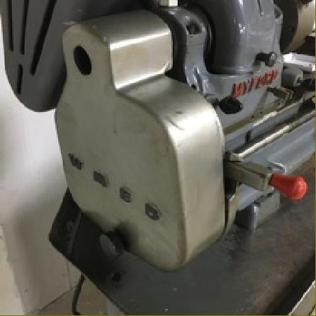
More photographs of the Super 7 Plus
Myford Super 7 Connoisseur
Fitted with numerous extras as standard this was the last Super 7 to be introduced. Amongst the expensive additions were an inverter-controlled, variable-speed drive from 26 to 3000 r.p.m.; crewcutting gearbox; hardened bed; spindle indexing (by use of the backgear bullwheel); Poly-V drive to the headstock spindle and the "new-type" industrial stand as used on the 254
ML7 Tri-Leva:
Designed to fit the headstock of the ML7 (but not Super 7) the Tri-Leva was an attachment intended to perform both as a clutch and allow instant changes of spindle speed. The device was beautifully made and finished and consisted of a lower housing (bolted into place under the headstock spindle by three extended-thread headstock bolts) that acted as both a mounting shelf for the upper part of the unit and an alignment guide for the three permanently-mounted drive belts that formed the heart of the conversion. The upper part of the unit, fastened to the countershaft, held a similar belt guide and three spring-loaded rollers, each of which could be pressed down to engage its own V belt. An interconnecting mechanism released the "engaged" selector when the handle of another was depressed. The Tri-Leva was expensive, especially when equipped with the optional two-speed motor and associated switches; in 1962, for example, it would have added 35% to the £70 : 15 : 0d cost of a Standard ML7. As a result, most units appear to have been fitted on lathes bought by professionals and intended for production work. More Tri-Leva details can be found
here
Myford ML7R:
Introduced at more or less the same time as the power cross feed Super 7, this is the lathe that confuses people new to the make. Although called an ML7 - and you would therefore expect it to be a development of, or directly related to, the original machine of that name - it was actually a non-power cross feed Super 7, but without a clutch and fitted with ML7 cross and top slides. It was designed to replace the ML7 and allowed a rationalisation of production around just one type of bed, headstock and tailstock. However, the lathe was not to last, and later the lathe was to be fitted with Super 7 cross and top slides and the "new" lathe renamed "Super 7 Sigma".  Photographs of the ML7R here
Approximate weights with electric motor:
Standard ML7: 185 lbs. (84 kg).  Long-bed ML7: 215 lbs (98 kg)
ML7R: 240 lbs (109 kg)  Long-bed ML7R: 270 lbs (122 kg)
Super 7: 245 lbs. (111 kg.). Long bed Super 7: 275 lbs (125 kg)
A screwcutting gearbox adds about 15 lbs
Drive Belts - Lengths required:
Super 7 & ML7R:  Headstock spindle belt A section 29.5" (use 750 mm) 
Motor to countershaft M section 33.5" (use 850 mm)
ML7:  Headstock spindle belt A section 23" (584 mm) 
Motor to countershaft Z/M section 347/16" (875 mm)
Tri-leva:  Headstock spindle (3 belts) A section 23" (584 mm)   
Motor to countershaft M section 347/16" (875 mm)
(All these belts, standard and link, are kept in stock for delivery by return of post)
Myford ML10:
Now out of production in all its forms, the ML10 at 3.25" centre height and 13" (later 18") between centres was Myford's smallest modern lathe. Designed as an economical machine, especially suitable for beginners, the first one left the production line on November 14th, 1968 (though brochures had been received by dealers as early as January of the same year). With a flat-topped, V-edged bed (identical in form to that employed on the wonderful toolroom Hardinge HLV-H lathe) the ML10 was a perfectly-adequate small machine tool - though it did lack several of the refinements to be found on the company's larger lathes i.e. there was no gap in the bed, no tumble reverse, the backgear was not mounted on an eccentric but in a slotted bracket - and the headstock was clamped rather than bolted to the simple, flat-topped, box-section bed casting.  It occupied 35.75" in length (an ML7 was 42") and around 22" in width (almost identical to an ML7). On pre September 1985 models the countershaft/motor-unit was a separate assembly that had to be mounted on the bench, behind the lathe, with an adjustable "over-centre" belt-tensioning device to couple them together. Later machines, from Serial No. 159991 on the 11th of September, 1985, were improved and the lathe mounted on headstock and tailstock raiser blocks with the former being extended backwards to form a mounting for the motor-countershaft unit. Thus, like the ML7 and Super 7, the lathe became a complete unit and much easier to install and transport.
With three direct-drive and three geared slower speeds the ML10, unlike most of its European and Far-eastern competitors, had a proper, robust backgear assembly (the backgear bull wheel on the spindle was identical to that used on the ML7) and, so equipped, a very powerful drive was available with the slowest speed of 25 r.p.m. enabling it to cope with large diameter jobs and screwcutting. In addition, instead of miniature (and expensive) "Gates" belts Myford chose to use reliable, full-sized, inexpensive and easily-obtained "A" section V-belts.
ML10 Headstock:
On early and late machines the headstock was different. The first model, with six speeds and a maximum of around 840 rpm, had a hardened spindle that ran directly in split bearings formed as part of the headstock casting. This combination of hardened steel running in cast iron (partially self-lubricating due to the free graphite found in the latter) is excellent from the wear point of view - and I have yet to find any ML10 with the headstock bearings in poor condition. You may be quite confident that this design principle is correct - tens of thousands of American South Bend (and other makes) have been constructed in this way - and are still going strong. The bearings on the ML10 were split on one side only and provided with a clamping screw; the space between each split was filled with a thick shim to provide a firm surface onto which the top cap could be pulled down. If the headstock bearings appear to be in correct adjustment it is important not to fiddle with them; simply ensure that they receive regular lubrication - and under no circumstances remove the shims. It is possible to vary the speed range of an ML10 by changing the size of the electric-motor pulley, but do bear in mind that the maximum recommended speed of a plain-bearing ML10 is 1280 rpm. Later machines, produced from January 18th, 1978, (from machine V137261) were fitted with grease-lubricated roller-bearing headstocks that, although provided by the factory with the same speed range as the earlier machine, can easily and safely be adapted by their owners to run as fast as the later "Speed 10" version (see below for details).
ML10 Changewheels, Screwcutting and Metric Conversions:
Available in both full metric and imperial versions each had compound-slide feed screws, micrometer dials and the leadscrew to the correct specification. To convert an imperial machine to metric screwcutting required only two 21t changewheels in addition to the normal set (it was not necessary to change the leadscrew) - while to convert the rest of the lathe to a metric specification (or the other way round) needed only the substitution of the correct cross and top-slide feed screws, nuts and micrometer dials. The lack of a tumble reverse meant that a reversing stud (mounted behind the spindle in a slotted bracket)  was necessary to cut left-hand threads; the changewheels and their mounting studs, fastened to a simple, single-slot banjo, were identical to those on the ML7.  The imperial leadscrew pitch was the same as the 7 Series lathes (eight threads per inch) and was available fitted with an optional and very useful dog-clutch that allowed the leadscrew drive to be instantly engaged and disengaged. On imperial machines from Serial No. V144354 the diameter of the threaded side of the leadscrew was increased from 5/16" BSF to 3/8" BSF with the same increase on metric versions from V144464.
ML10 Compound Slide, Apron and Saddle Assembly:
Although the cross slide was a little smaller than that on an ML7, the micrometer dial, hand-wheel and standard toolpost were identical. The cross-slide T-slots were spaced the same distance apart (which allowed a standard ML7/Super 7 vertical milling slides to be used) but the 4-way toolpost and rear toolpost were unique to the machine. The top slide fitting resembled that on the Super 7 with an inverted cone used to take the thrust from two opposing push bars that caused it to lock down onto the cross slide.
Geared directly to the leadscrew, the carriage handwheel and incorporated a thread-dial indicator; however, because the direct gearing caused the saddle travel to be rather "high-geared" (i.e. you turned the handle a little, and the saddle moved a lot) the leadscrew was provided, as standard, with an un-graduated handle at its right hand end. Used with the clasp nuts engaged, the leadscrew able to provide a much smoother and steadier saddle movement. From machine number V167714M, on the 27th of March 1993, the previously optional-extra 'long cross slide' was fitted as standard.
Speed 10:
On the 4th of May 1979 a modified "two-speed" countershaft unit was introduced that carried an eccentrically-mounted top shaft with a double-step V-belt pulley drive from the motor; this arrangement doubled the number of speeds to twelve (of which ten were officially sanctioned as safe to use) with a range from 48 to 2000 r.p.m. This new model,  the "Speed 10", was identified by the prefix "VS" and the first down the production line carried the Serial Number VS143202M. Just one month later, on the 6th of June, the first Long-bed Speed 10 was manufactured (numbered VSL144264); with its 18-inch capacity between centres this model was introduced in an attempt to bridge the gap between the ML7 and ML10.
A useful little machine, the ML10 was perfectly capable of tacking most jobs that the model or development engineer would wish to attempt, the only drawbacks being the simplicity of its construction - and basic controls. A friend, who is a full-time experimental and development engineer, bought a plain-bearing example n his impecunious days and held on to it for twenty-two years, finding it indispensable for all his small turning. With a 3-inch precision chuck mounted he often ran it (for short periods only) up to 40000 r.p.m. without any harmful effects, though he had fitted drip-feed oilers to the bearings and ran them with a high per-minute drip rate. The last incarnation of the ML10/Speed 10 was the "Diamond 10", introduced on November 27th, 1993 and only sold directly from the factory - the first time that Myford had ever used this marketing technique. A comparatively rare machine on the used market, the ML10 sold in fewer numbers than the larger models - although, to be fair, the latter did have a twenty-two year start. 
Like other Myfords the ML10 was cloned - one version (illustrated below) being sold in the UK by the long-established importer of far Eastern machine tools, Warco.
Used Myford lathes of all types can often be found for sale on this page:
** Ted Barrs served his engineering apprenticeship during the 1920s, completing it alongside his best pal, Bill Day, who went on to found
The North London Saw Works, at Waltham Cross - a business still running today (2014).
In 1931 Ted married and, with twin daughters born in 1935, moved to Beeston in 1942 to take up employment with Myford. Like most of his generation in senior engineering positions he was a hands-on man and, when his apprentices found a job too difficult, he would go down to the shop floor and demonstrate how it should be done.
Popular with both the owners (the Moore family) and with the workforce he rose to become Works manager. However, even after he retired he would spent many hours each week at the factory in an 'advisory' capacity - he really did live and breathe Myford machine tools.
Every year his young nephew Phillip, together with his father, I would go to the Model Engineering Exhibition in London, not only to see the models on display but, just as importantly, to see Ted. One visit Phillip spent an hour on the Myford stand learning woodturning from their demonstrator, a Mr. Fred Payne; "
He taught me more about the craft in an hour than I would ever have learnt at school in a year."..


Ted Barrs; designer of the Myford ML7 and ML8 and one-time works manager at Myford Engineering

For many years the first Myford factory building - it had once been a lace works - was a landmark in Beeston, Nottingham. Unfortunately, years of machine-tool production had left the floor boards soaked in oil and it was finally condemned as unsafe by the fire brigade - and had to be demolished. This was probably no bad thing for Boxford's Factory, an old mill, was burnt to the ground some years ago - the oil-soaked flooring in that playing a major part in the ferocity of the blaze..       

Specification sheet from the first comprehensive ML7 catalogue