 |
|
|
|
|
|
|
|
|
|
|
|
|
|
|
|
|
|
|
|
|
|
|
|
|
|
|
|
|
|
|
|
|
|
|
|
|
|
|
|
|
|
|
|
|
|
|
|
|
|
|
|
|
|
|
|
|
|
|
|
|
|
|
|
|
|
|
|
|
|
|
|
|
|
|
|
|
|
|
|
|
|
|
|
|
|
|
|
|
|
|
|
|
|
|
|
|
|
|
|
|
|
|
|
|
|
|
|
|
|
|
|
|
|
|
|
|
|
|
|
|
|
|
|
|
|
|
|
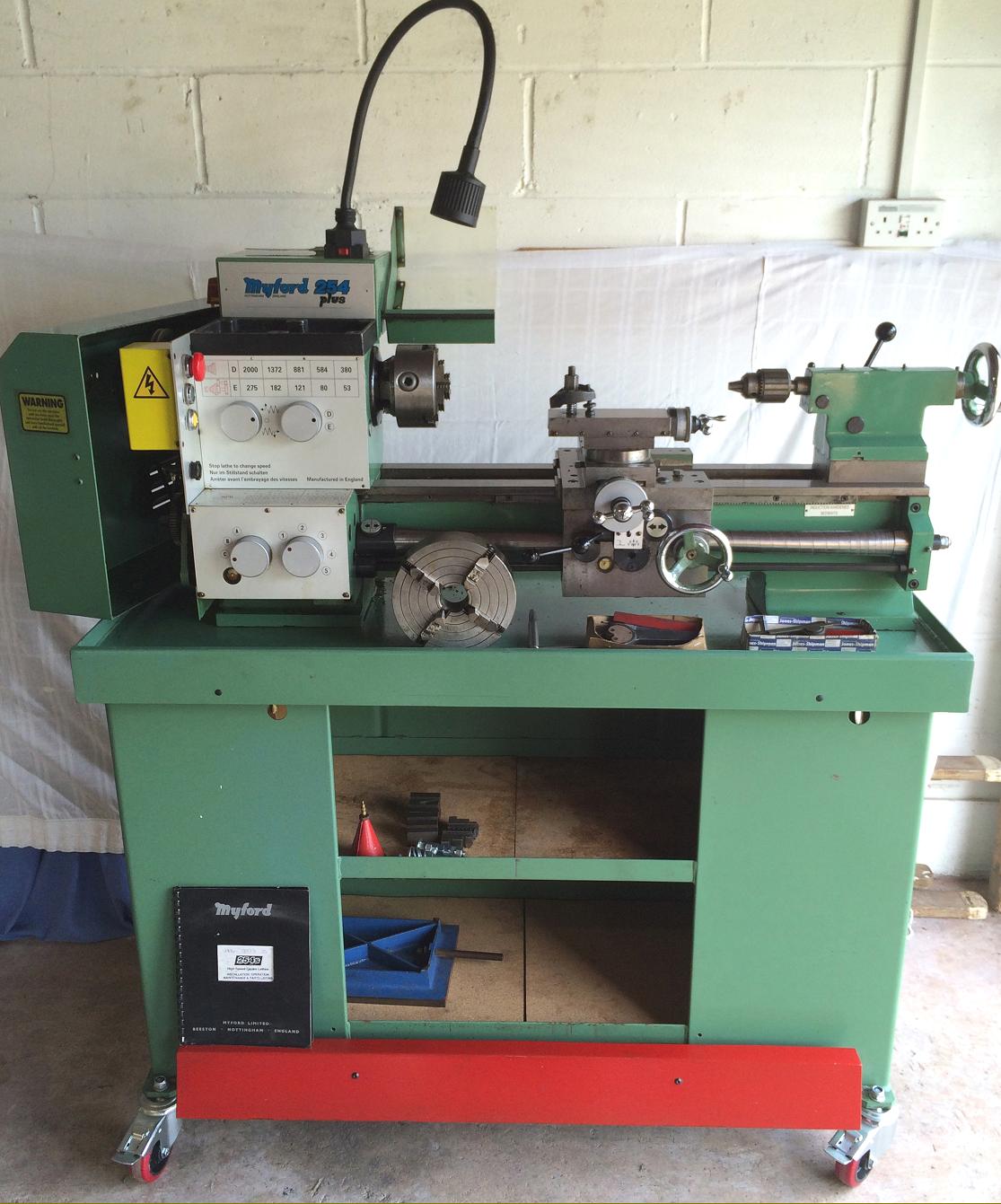
Although Myford had toyed with the idea of a larger lathe in the 1960s with their beautifully-made, short-lived and expensive-to-produce geared-head 280, the 4.75-inch centre height "254" (the number derives from the swing in mm) marked Myford's first sustained move into the field of larger types. Introduced in 1984 to span the needs of model engineers and light industrial users two versions were announced simultaneously, both constructed from the same basic components: the entry-model 254R and the more sophisticated 254S. The 254R used changewheels for screwcutting, lacked power cross feed and was sold as standard with an unhardened bed and the same arrangement of cross slide as the super 7 with a bridge-type end bracket, small micrometer dials and the feed-screw nut fixed into the front wall of the saddle. By contract the 254S had an induction-hardened bed (to 45 Rockwell; 450 Vickers) together with a screwcutting and feeds' gearbox and power sliding and surfacing driven from a separate shaft below the leadscrew. The power-feed arrangement necessitated not only a new apron but also a different design of cross slide drive with a Boxford-like bracket fixed to the face of the saddle and the cross-slide nut carried on the underside of the cross-slide casting. Another consequence of the power feed set-up was the need to move the saddle-to-bed gib strip from the front of the carriage (as on the 254R) to the rear where, in theory and an ideal world, cutting forces should come up against a "solid" metal-to-metal fitting and not through adjuster screws. However, in the writer's experience of a 254, this appeared to make not a jot of difference with even heaviest interrupted cuts failing to induce chatter. Other differences included very much larger, very clearly engraved satin-chrome micrometer dials on both cross and top slide and a thread-rolled leadscrew protected by a fully-enveloping "spiral" spring cover - the latter two items being standard on all subsequent variants. Although the cover gave the leadscrew absolute protection from wear caused by swarf (and guarded against the operator's clothes being caught) it could be sprung away from the left-hand face of the apron for lubricant to be applied.
Continued below:
|
|
|
|
|
|
|
|
 |
|
|
|
|
|
|
Early 254R--the basic model
Continued:
Cast in the UK from gray iron to B.S.1452 - Grade 7 the 150 mm wide straight bed (there was gap option) featured large circular chip-clearance holes between the ribs. The ways were flat and the shears vertical - a feature on all Myford 7-Series lathes - and deliberately chosen to allow the machine to be used for milling with either a traditional vertical slide carried on the T-slotted cross slide, or from an optional powered vertical milling head (by a third-party English maker Rishton) bolted to the rear of the bed. The maker's thinking behind the use of flat ways (long considered an essentially English design) was the need to absorb thrust from all directions and make the lathe as adoptable as possible for the greatest number of users. Two bed lengths were offered giving just over 21-inches between centres as a short-bed model and just over 31-inches as a long bed - though in each case a little more capacity was available by letting the tailstock casting overhang the end of the bed (but with the clamp plate still fully engaged, of course).
If the bed form was traditional the enclosed, box-section headstock reflected a good deal of modern thinking where, although it had the appearance of a geared-head machine, drive was by a narrow (Z section) 5-step V-belt pulley overhung from the left-hand end of the spindle. This layout, which at a stroke removed the necessity of accommodating a pulley between bearings, was identical to that used on many smaller lathes: for example, the pre-war English EXE and the Austrian Emco Maximat 3000 and Standard Series of the 1960s. However, unlike the Emco models, the 254 enjoyed a range of (properly) geared lower speeds by the use of an oil-bath lubricated speed-reduction gearbox built into the headstock. The gears were hardened and then ground using the "Reishauer" process, a method that resulted in a precise tooth form and hence unusually quiet running on slow speeds. 10 spindle speeds were available from 53 through 80, 121, 182 and 275 in low and 380, 584, 881, 1372 and 2000 r.p.m. in high. This was a range slow enough for threads to be cut safely by amateurs yet fast enough to allow the use of carbide tools and high rates of metal removal by the more experienced. Although a well-designed and smooth-running arrangement its control was not without some awkwardness with the engagement of slow speeds requiring the necessity to first disengage the spindle-pulley coupling - by unscrewing two socket screws at the left-hand end of the spindle until the assembly "locked" - before turning the headstock-mounted knob to engage the gears. As a point of interest should you ever have occasion to dismantle a 254 headstock on all but the very earliest models the pulley assembly is located on the spindle by the interference-fit of its needle roller bearing and to remove it a special puller is required.
Continued below:
|
|
|
|
|
|
|
|
|
|
|
|
|
 |
|
|
|
|
|
|
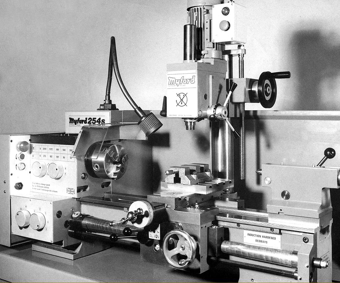
Myford 254S This much improved model had a screwcutting gearbox, power cross and longitudinal feeds from a separate power shaft , enclosed leadscrew, large micrometer dials and a more complete electrical system as standard. Myford 254S Photo Gallery here
Continued:
Although fitting a pulley to the end of the spindle might have seemed an easy answer to lower production costs, Myford ensured that the set-up was properly engineered and used a particularly stiff, ground-finish spindle forged from an 11 kg billet of top-quality steel that ran in precision taper roller bearings. The spindle was bored through to clear 26 mm, fitted with a useful 4 Morse nose and came with a choice of a B.S.4442-A3 or, at extra cost and very much more desirable, a D1-3" camlock nose as commonly used on small industrial lathes. Both fittings allowed accessories to be mounted close to the front bearing with the minimum of overhand and, while the B.S. nose required chucks and backplates with 3 inconvenient studs and nuts to fasten them in place, at least it uses the same tapered spigot as the more convenient D1 fitting and so allows accessories to be made or adapted with comparative ease should factory parts ever dry up.
Fixed to a pivoting bracket on the back of the bed (and with a good-sized locking lever to ensure it could be quickly adjusted to allow changes of speed) the 0.75 h.p. 1425 r.p.m electric motor could be had as a 1-phase resilient-mount or 3-phase solid-foot unit. Because 1-phase motors have a characteristic "pulsing" vibration Myford arranged what they called "O ring" damping in the bolt assembly that set the belt tension.
Up-to-date, and including either a basic D.O.L. reversing switch or, at extra cost, a complete safety package, the electrical system included a transformer to produce 110 volts for the push-button "no-volt" release starter and a 12v tapping for the optional halogen light unit. Machines produced in later years always reflected contemporary safety requirements with the addition of built-in controls, including (amongst others) thermal overload and no-volt releases, a mushroom-headed stop button and safety cut-off switches on the main-drive enclosure and chuck guard. Later electrical options (at extra cost) included D.C. spindle braking, an emergency footswitch and a saddle-travel limit switch.
Besides the "backgears" the interior of the headstock also carried the changewheel drive reverse gears - replacing a conventional tumble-reverse assembly - and shared its lubricant supply with them. On the 254R the drive passed to the exposed, 3 mm pitch or 8 t.p.i. leadscrew through a set of changewheels (using the same DP gears as on the 7-series) while the full screwcutting gearbox (on the 254S) drove an enclosed leadscrew and gave pitches from 0.25 to 5.0 mm or 4 to 56 t.p.i. (with one changewheel alteration) and longitudinal feed rates from 0.04 to 0.32 mm (0.0019" to 0.32") per revolution of the spindle. Cross-feed rates were approximately half those of the sliding. The screwcutting gearbox was completely enclosed and fitted with hardened gears running in an oil bath. Changes of ratio were made by knurled-edge dials, which though of neat appearance, were not as easy to grip with oily fingers as levers. Both boxes were available with conversion gears to cut metric or imperial pitches. On the 254S the leadscrew was engaged only for screwcutting - through a dog clutch engaged by a small dial at the headstock-end - with a separate power shaft to drive the sliding and surfacing feeds. As a protection against overloads, or an accidental running of the carriage into the chuck or tailstock, an adjustable plate clutch was fitted that slipped automatically at a preset load. The clutch can, under prolonged hard use, start to slip and needs to be adjusted with the supplied C spanner. As an option, multi-stops were available for both feed directions that could be used for repetition turning by allowing the drive to run against them and cause the clutch to slip. Not as good as complete disengagement, but still useful.
Continued below:
|
|
|
|
|
|
|
|
 |
|
|
|
|
|
|
Top-of-the-range 254 Vari-speed with Rishton-manufactured vertical head
Continued:
Arranged with double walls the apron contained an oil bath in the base from which lubricant was distributed by splash. The carriage handwheel was fitted with a large, zeroing micrometer dial and on power-feed versions a knob selected the direction of feed, with a lever lifted and depressed to engage, respectively, longitudinal and cross feed.
Typically Myford in design, the full-length, 5 T-slot cross slide had an effective lock and a generous 162 mm of travel (6.375") -a figure that made it especially useful when used together with a vertical milling slide, . The top slide, like that on the Super 7, was retained by an inverted cone and two pusher screws and could be swiveled through 360 degrees. Both feed screws were fitted with Torrington NTA-815 roller anti-friction thrust races and TRB-815 thrust washers with the clearance set by the factory at zero and not subsequently adjustable. However, and rather surprisingly, the single toolpost fitted as basic equipment to both lathes was identical to that used on the ML7 of the 1940s.
A little disappointingly the set-over tailstock carried only a No. 2 Morse taper barrel instead of a No. 3 (as used, for example, on the Viceroy 5-inch) but with 70 mm (2.75") of travel driven by a quick-action, 2-start thread with a particularly smooth action..
Subsequent development of the 254 saw the 254S with a standard-fit, screwcutting gearbox, power cross and longitudinal feeds from a separate power shaft , enclosed leadscrew, large micrometer dials and a more complete electrical system as standard. In 1989 a revised machine, the "254 Plus", took things further with its center height increased to 5.34 inches (by the simple means of deeper castings for the headstock, tailstock sole plate and top-slide lower casting) and a variable-speed drive system on the "254 Plus Vari-Speed". Myford 254V-Plus Photo Gallery here. The lathe (also listed as the 254V Plus), used a 1.5 kW (2 h.p.) 3-phase motor with inverter drive from a 1-phase supply that, due no doubt to misgivings about longevity, Myford guaranteed for three years. Speeds ran from 30 to 275 r.p.m in low range (using the headstock reduction gears) and 250 to 2000 r.p.m in direct drive with the power transmitted from motor to headstock pulley by a wide Poly-V belt. The Vari-speed was available only as complete unit mounted on the maker's stand and with the electrical system ready fitted. A digital tachometer was fitted together with a 10-turn potentiometer for speed control. Initially the "Plus" was listed as available for bench mounting and the "Vari-speed" only as a complete unit, fitted to a tray-top cabinet stand some 1256 mm long (1506 mm long bed) and 432 mm deep (710 mm with a splash back). However, by the mid 1990s both models were listed as only being available fitted to a stand and with all the essential electrical equipment installed as a factory package. Prices at the time (including tax) ranged from £4935 for a basic 254 Plus to £6703 for a long-bed Vari-speed. Weights varied between 173 kg for a basic bench-mount 254R model through 309 kg for a stand-amounted, short-bed 254 Plus Vari-speed to 363 kg for the long-bed version. However, a fully specified long-bed Vari-speed model, mounted on the maker's stand, equipped with a DC injection spindle brake and fitted with a VM-A powered vertical head could be as high as 450 kg.
With a comprehensive specification, compact dimensions, an excellent speed range, quiet running and the easy availability of spare parts all versions of the 254 are greatly sought after and retain their value especially well..
|
|
|
|
|
|
|
|
|
|
|
|
|
|
|
|
 |
|
|
|
|
|
|
Myford 254 S with the Rishton-built vertical milling head
|
|
|
|
|
|
|
|
 |
|
|
|
|
|
|
|
|
|
|
|
 |
|
|
|
|
|
|
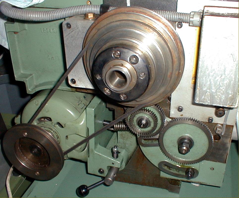
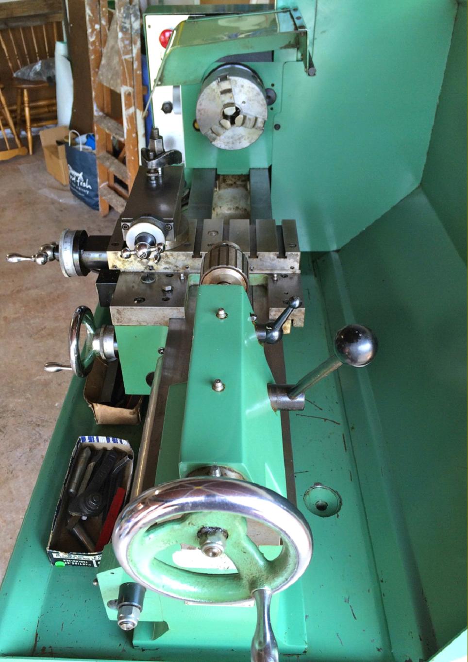
Myford 254 Drive System. Motor platform with spring-loaded tensioning lever and five-speed V belt drive. To engage the gear-driven slow speeds two Allen screws in the end flange of the headstock drive pulley are first loosened allowing the drive tabs to emerge from their recesses. Once these are out, the appropriate dial on the face of the headstock can be turned to engage the gears - a rather slow and frustrating system.
|
|
|
|
|
|
|
|
 |
|
|
|
|
|
|
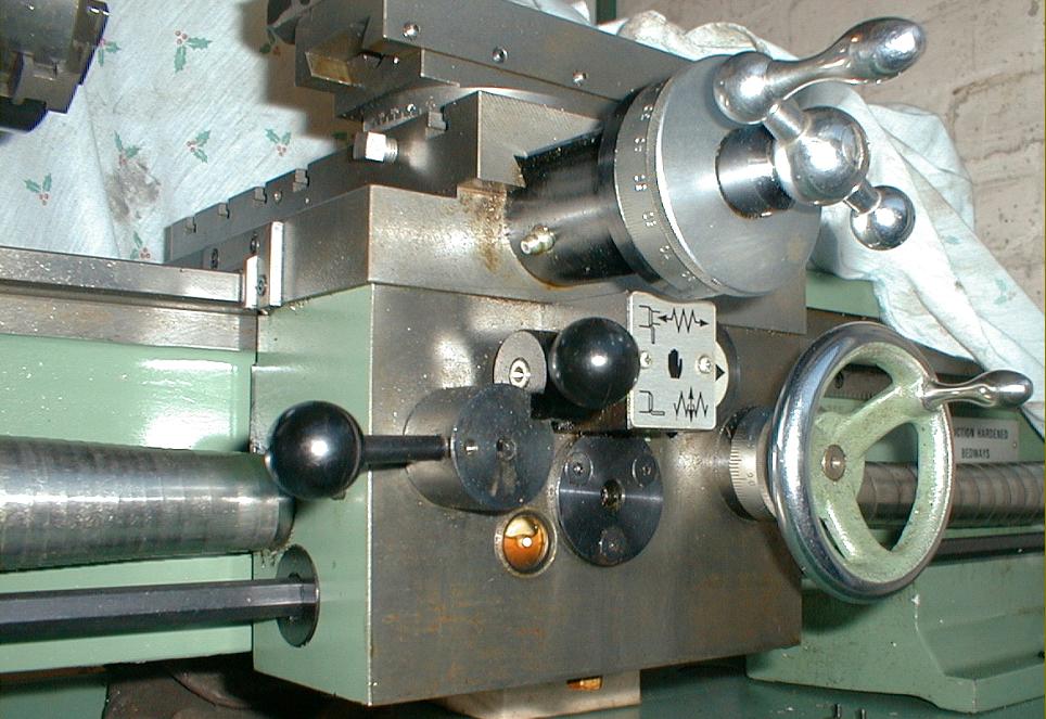
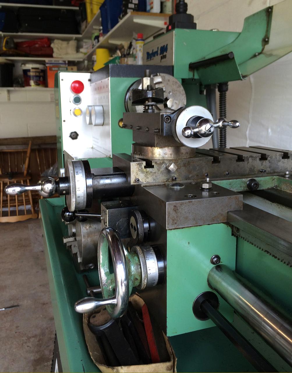
Myford 254 Apron Details. Oil-filled apron with level window and simple but foolproof interlock on power feed and screwcutting engagement levers
|
|
|
|
|
|
|
|
 |
|
|
|
|
|
 |
|
|
|
|
|
|
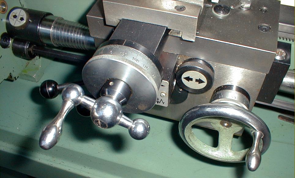
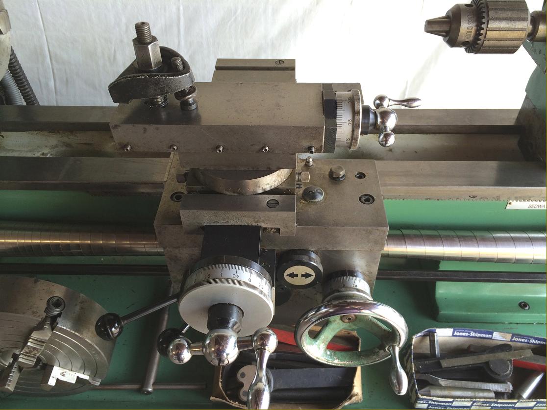
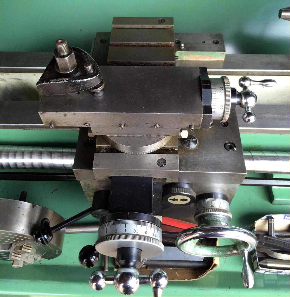
Myford 254 Apron Details. Large, clear cross-feed micrometer dial, graduated and zeroing dial on the saddle traverse handle and the button marked with a double arrow to select power sliding or surfacing
|
|
|
|
|
|
|
|
|
|
|
|
|
|
 |
|
|
|
|
|
 |
|
|
|
|
|
 |
|
|
|
|
|
 |
|
|
|
|
|
|
|
|
Myford 254 taper-turning attachment
|
|
|
|
|
|
|
|
|
|
 |
|
|
|
|
|
|
|
|
|
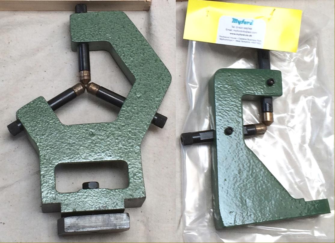
Myford 254 fixed and travelling steadies
|
|
|
|
|
|
|
|
|
|
|
|
|
|
|
|
|
|
|
|
|
|
|
|
|
|
|