 |
|
|
|
|
|
|
|
|
|
|
|
|
|
|
|
|
|
|
|
|
|
|
|
|
|
|
|
|
|
|
|
|
|
|
|
|
|
|
|
|
|
|
|
|
|
|
|
|
|
|
|
|
|
|
|
|
|
|
|
|
|
|
|
|
|
|
|
|
|
|
|
|
|
|
|
|
|
|
|
|
|
|
|
|
|
|
|
|
|
|
|
|
|
|
|
|
|
|
|
|
|
|
|
|
|
|
|
|
|
|
|
|
|
|
|
|
|
|
|
|
|
|
|
|
|
|
|
|
|
|
|
|
|
|
|
|
On this page - MYFORD ML7 , ML7 Tri-Leva, SUPER 7, ML7R,
Super 7 Plus, Super 7 Connoisseur, ML10 & Speed 10 Lathes
When, in September 1934, Cecil Moore founded the Myford Engineering Company and rented a spare room in a 5-storey lace mill in Beeston, Nottinghamshire (the address in the early sales sheets was given as Neville Works) few could have foreseen the day when, ten years later, he was to occupy all but a fraction of the same building and to continue trading, as the same company, until August 2011. The foundation of this success - and the rise of Myford to pre-eminence amongst the then many competing makers of small lathes - was a range of just four machines: the very similar ML1, ML2, ML3 and ML4. Neat, compact and of appealing appearance all were designed and priced to appeal to the amateur market. However, despite their success, not even the most enthusiastic of owners could boast of them as state-of-the-art products and, by the close of the decade, the new-for-1937 American Atlas 6-inch (with its all-V-belt drive countershaft, roller-bearing headstock, fully-guarded changewheels and a host of user-friendly details) was setting the benchmark for hobby-lathe design. In response, and designed during the closing years of WW2 (1939-1945) by Ted Barrs**, Myford launched what was to become the most popular and sought after small lathe in the UK, the ML7.
Undoubtedly drawing some design influence from American Atlas machines (including the 10-inch) the ML7 designed during 1944 and 1945 and announced to the press in February 1946. The first ML7 catalogue was stamped "Provisional" and printed in the same A5 landscape format used for ML2 and ML4 publicity material; the cover was dark-blue with the single word "Myford" picked out in gold and in the company's traditional script. The pages were typed, reproduced on a Gestetner, and contained just one photograph showing the lathe mounted on its special "octagonal-form" braced sheet-steel cabinet stand. The first proper, fully illustrated catalogue was issued in October 1947 and contained not only a complete technical specification but also cut-away diagrams and a list of the many and varied accessories.
From the start of production the ML7 was designed to accept a variety of profitable accessories (all listed and illustrated in the first full catalogue dated October 1947) and very soon, with such an expandable and properly-engineered English small lathe on offer for the first time, many ex-service men (with gratuities burning a hole in their pocket) caused a lengthy waiting list to develop. The works prefix for the ML7 was "K" - with other contemporary designations including the ML.5 Capstan lathe being found as both the "F" and "R", the M.U. capstan as the "G", the M.L.6 capstan as "H" and the Myford/Drummond M-Type as "J". By the early 1950s, with just the ML7 in production (though a popular cylindrical grinder, the first of many, had also been introduced), it was decided that the market could stand the addition of a significantly altered and more highly developed lathe. Thus, in late 1952, the Super 7 was launched (with the provisional catalogue dated November of that year) - a machine that was able to accept all existing ML7 accessories.
Although popular, neither the ML7 or Super 7 was never inexpensive, but have always been excellent investments. Constructed using top-quality materials and assembled with care and finished to a high standard - even to the extensive use of fully-machined and chemically blackened nuts, bolts and other fasteners - they hold their value well. However, early ML7s and the first Super 7s were not as well finished as the post 1960 machines (when additional filling, sanding and a better quality paint were all introduced) and, in the rush to get jobs "through the door", often a single coat of paint was sprayed directly onto castings left largely as they had arrived from the fettling shop. Amusingly, the writer remembers a letter from an ML7 owner to the Model Engineer Magazine complaining about the poor finish. As this was the late 1940s and advertisers had great pull over what magazines said about their products, the next issue of the magazine contained what was, in effect an apology (for telling the truth…)
Today, the ML7 and Super 7 are both firmly in the "classic" category and two versions of the latter remained in production until the end, the large-spindle bore, power cross feed "Super 7 Plus" (in various forms including one with variable-speed drive) and a model much more like the original and without power cross feed, the "Sigma 7".
Capacity:
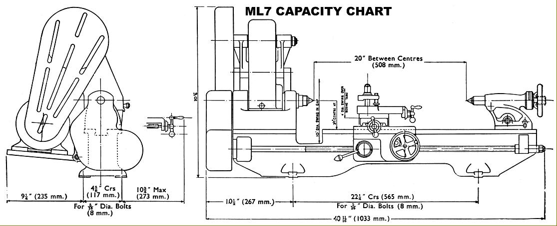
Both lathes can turn a maximum diameter of 7" over the bed and 10" by 1.5" thick in the gap; between centres the ML7 can handle material up to 20" in length and the Super 7 19" - or both a little more if you allow the tailstock to overhang the end of the bed. An ML7 is around 42" long and occupies a space about 22" front to back while a Super 7 is approximately 46" long and a little deeper than the ML7 at around 27". Surprisingly, a bench as little as 16" deep from the wall will accommodate an ML7.
There were long-bed versions of both lathes: these admitted 31" between centres and were constructed with a very much deeper bed wall. Interestingly, the long-bed ML7 was fitted, as standard, with parts from the Super 7: apron, leadscrew, saddle and (slightly modified) cross and top slide units - although oddly, despite its appeal, this improved specification was never mentioned in contemporary catalogues. As an aside, although the cross slide on the long-bed ML7 (or at least some of them) appears to have been a standard Super 7 unit, its end bracket and the method of assembling the cross-feed screw to it were different (specification sheets for both ML7 and Super 7 are at the bottom of the page).
Continued below:
|
|
|
|
|
|
|
|
|
|
|
|
|
|
|
|
|
|
|
|
|
|
 |
|
|
|
|
|
|
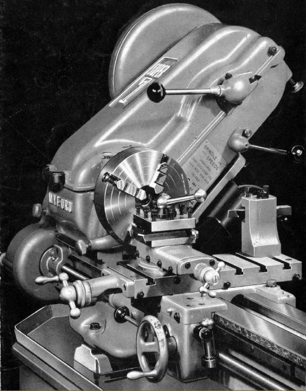
Myford ML7 3.5" x 20" gap bed, backgeared and screwcutting
as it appeared in the late 1940s and early 1950s
ML7 - General Specification (full dimensions sheet at the bottom of this page):
Of ribbed box-section, the bed was constructed with a flat top of typically English style, with narrow vertical shears, the nearer one in the gap between the front and back ways being shared by the saddle and tailstock. This was not an ideal situation but, in practice, caused no problems until the bed became badly worn when, as the tailstock was brought close to the headstock, it's central locating tennon became loose. With all the main surfaces at either the same level or at a right-angle to each other, one advantage of the bed design was the relative ease of regrinding with set-up times greatly reduced. The back face of the bed was machined flat and equipped with tapped holes ready to accept a taper-turning attachment. The design of the saddle was interesting: shimmed plates were fitted at front and rear by which means a very close vertical fit could be obtained; at the front, instead of a full-length inner lip, just a short one was employed, no wider than the cross slide, and it was on this surface that tool thrust was taken. A consequence of this quirk is that the four gib-strip adjustment screws along the front edge of the saddle take some skill to set correctly with only two bearing against a firm surface; to get the setting correct the maker's instructions have to be followed to the letter. Towards the end of ML7 production, a New Zealand engineer pointed out that it would be better if the tool thrust was to be taken along the full length of the saddle's inner rear face by using the bed's fourth vertical shear counted from the front. By this means an otherwise unused already-machined surface could be used and (combined with an adjustable gib strip) a much longer and more stable contact obtained. Unfortunately, the New Zealander's proposed method, while possible in an experimental situation, was not suited for production and so Myford - probably following the appearance of an article in Model Engineer Magazine proposing a similar but rather more straightforward modification - came up with a system (from K107657) that involved machining away the original short contact lip at the front and using a modified casting to keep the relative position of apron and leadscrew the same. By this means the saddle to bed contact was arranged against the rear shear, yet the gib strip adjustment kept at the front.
Apron
Pressure die-cast in a form of ZAMAK (it looks like aluminium), the apron was fastened to the saddle with three cap-head screws and with the leadscrew clasp nuts guided in adjustable, gibbed ways. On early machines, the reduction gearing between carriage traverse handwheel and rack was exposed (and quickly collect swarf and dirt) - but this fault was soon corrected and a close-fitting cover provided.
Cross and Top Slides
While the Super 7 was fitted from the start of production with a long slide as standard that on the ML7 was always shorter (with 5-inches of travel and four 3/8" T-slots) but with the option, at extra cost, of a longer 10.75-inch slide (and matching longer feed screw) with five T-slots. Even so, the standard slide had a generous 30 square inches of clamping surface and, with the top slide removed, was ready to be used as a miniature boring table or to mount a milling slide or rear toolpost. Until Machine K108718, slotted BA screws and locknuts were used for the gib-strip adjustment but were then replaced by easier-to-set self-locking 5-mm pitch hexagon-socket screws .
Able to be swivelled 63-degrees either side of zero, the 2.5-inch travel top slide was fitted with the same 10 t.p.i. Acme-form feed screws as the cross slide and both carried identical micrometer dials die-cast in ZAMAK; while a "character" part of the machine the early dials are not as easy to read as the properly-engraved units fitted to very late models. The toolpost clamp post was surrounded by three tapped holes, these being intended to accept the mounting screws for the indexing plate used on the 4-way toolpost; as supplied from the factory each hole was sealed with a small grub screw to prevent swarf working its way through to the feed screw and wearing it out.
Headstock
In comparison with almost every other contemporary small (British) lathe, the headstock of the ML7 was a rugged affair. Bolted to the bed by four high-tensile cap-head Allen screws it was aligned by a ground rectangular locating tongue fitted into the gap between the bed ways with two pusher screws, entering from the rear, pressing against the tongue and so holding the headstock hard against the inner vertical bed way. The spindle was in 40-50 tons high-tensile steel and ran in plain, parallel Glacier TI Alloy "half-step" bearings with laminated (0.002") shims between the upper and lower halves to allow a reasonable fine clearance adjustment. Strong bearing caps were used, each bolted down by two socked-headed cap screws and with a ball-thrust bearing fitted in a shielded position at the left-hand end. The spindle was offset from the bed centre line towards the rear - a feature the makers ingeniously claimed in their first publicity sheet: "The distinct advantage of the offset is paramount when turning large diameters, the degree of rigidity being equal to that of a bed 5-inches wide with the headstock centrally disposed." The spindle on early machines was fitted with a pair of simple little No. 2 size wick oilers (easily neglected) while later models had proper drip-feed lubricators where the supply of oil could be adjusted (according to the spindle speed) and the quantity remaining easily inspected. The dimensions of the original spindle - 1.125" diameter, bored through 19/32", No. 2 Morse taper, front bearing section 1.25" diameter, rear bearing section 1", bull gear section 1.125", 12-threads-per-inch nose (the threaded section being about 0.62" long) backed by a plain register 1.25" in diameter and 0.4375" long - were carried over to the Super 7 and only changed with the advent of the new-for-2001 Super 7 Plus. The drive from countershaft to spindle was by a 3-step aluminium pulleys with a proper, full-sized A-section V belt that allowed full use to be made of the motor's power (generally 0.33 h.p. on early lathes and 0.5 h.p. on later). The robust backgear assembly (clustered at the front, beneath the spindle line) meant that speeds down to around 25 rpm could be achieved with greatly increased torque - and no risk of belt slippage - ideal for both screwcutting and turning large blocks of metal held in a four jaw chuck, or on a faceplate. On both ML7 and Super 7 that part of the (bronze) backgear carried on the headstock spindle was in the form of a "sleeve pinion" - that is, the small gear was extended to form a long bush on which the pulley was pressed, the whole assembly rotating on the spindle when backgear is engaged - a design that did much to enhance the lathe's ability to run reliably at slow speeds for long periods. Unfortunately, the assembly did contain a weak point: the three-step aluminium pulley was only pressed onto the sleeve - and it is not unknown for it to become loose and rotate. However, if the assembly is stripped, cleaned and the pulley secured onto the sleeve with a smear of low-strength Loctite, all will be well.
Changewheels and Screwcutting
Myford Series 7 10 changewheels of all years are 20 D.P. with a 14.5-degree pressure angle, 3/8" thick (0.375") with a 5/8" bore (0.625") and 1/8" keyway (0.125"). Supplied as standard with an ML7 or Super 7, the changewheel set comprised: 2 x 20, 25, 30, 35, 38, 40, 45, 50, 55, 60, 65, 70 and 75t. To cut a wide range of metric threads required, in addition, just two 21t wheels.
In place of the crude assembly used in pre-war years, with plain-bore changewheels running directly on studs and retained by split-pins and washers, the changewheel drive on the ML7 was properly engineered. Hardened steel pins were employed, carrying bushes keyed into the gears and with neat, quick-release washers retained by slot-head screws allowing the gears to be changed quickly. Unfortunately, the nuts holding the studs were still behind the banjo, making any alteration in position a fiddly, time-consuming business (on the Super 7 the nuts were moved to the front, and the design of pin assembly improved with the use of a bronze bush). The changewheels, like the belts, were enclosed inside a neat, thin-walled cast-aluminium cover. Tumble reverse was fitted as standard, allowing quick reversal of the saddle drive - and so speeding up the boring of deep holes, etc. Setting the tumble-reverse lever to "neutral" meant that high speeds could be used without having to drive the changewheel set - and this made an already very-quiet lathe even more acceptable in a domestic situation - many being used in attics and even spare bedrooms. The 8 t.p.i. left-hand thread leadscrew was of Acme form, 5/8-inch diameter and ran in Oilite bushes. On the original ML7 both the tumble-reverse and backgear levers were tipped with lovely little acorn-shaped plastic knobs - in what must have been a subtle reference to Nottinghamshire's woodland heritage. For details of the screwcutting gearbox fitted to the Series 7 Myford lathes, see the section below about the Super 7
Tailstock
Able to be off-set on its sole-plate for taper turning, the tailstock was fitted with a 1-inch diameter barrel, threaded 8 t.p.i. and with a No. 2 Morse taper - so allowing heavy-duty drilling. The barrel was bored clear and passed through the handwheel - an arrangement that did have some advantages, notably if used for long-hole boring when woodturning. Arranged so that it sat underneath the barrel - and so passed through the greatest mass of material - the tailstock spindle lock was of the proper (and powerful) split-barrel type. A further advantage of this location was that it removed the need to incorporate a boss on the back of the tailstock body to hold the locking mechanism, though there was a slight inconvenience in having to reach over to grip the lever.
Improvements
Although the ML7 changed very little during its production life some improvements were made: the early machines had no oil nipple on the headstock pulley (essential to lubricate the long bronze bush that was formed as part of the backgear) but this is easily retro-fitted; by 1950 the countershaft had been given more substantial uprights and the back made solid instead of having three open panels: the original ball-spring "Bennet" oilers were replaced by proper nipples to which a pressure oil gun could be applied to blast out dirt and drive oil to where it would do some good (note: all nipples, on all models of the Myford 7 Series, took oil, never grease): by 1960 the tailstock casting was filled in and its "off-set" guide moved to a thicker part of the casting: in 1969, from machine K90494, a cast lug was added to the headstock to provide a location point for the lever-action collet closer - this had previously been supported by a loose bronze bracket, clamped by two Allen screws to one of the cast-in strengthening ribs behind and immediately below the front headstock bearing.
During 1973, from machine K111727, production was rationalised around just one 7-Series bed, that for the newly-introduced, power-cross-feed Super 7, this being easily identified by a much deeper recess along the front face, a feature necessary to allow the much deeper power-feed apron to fit (there is a possibility that these beds were stamped with a serial number having a suffix "C". The change of bed also allowed the use of the Super 7 cast-iron apron and 3/4" diameter leadscrew (the Super 7 leadscrew nut clasp-nut handle is another recognition point). All these improvements that mean late versions ML7s have the very best specification of all. The last ML7 manufactured (K140848) left the assembly line on the 31st of January, 1979.
ML7: Speed Range:
As supplied to the UK market (with a 50 Hz 1425 r.p.m motor) the ML7 had a speed range of: 35, 62 and 110 in the 5.78 : 1 ratio backgear and 200, 357 and 640 rpm in open drive. Although it is perfectly possible to raise the top speed by increasing the size of the motor pulley, it is wise to bear in mind that the maximum recommended speed of the original white-metal bearing spindle is 1000 r.p.m. The writer has known machines to be run at much higher speeds, without apparent ill effect, but these were in good condition, carefully set up and with an increased flow of top-quality lubricant from their oilers; a worn machine treated like this might not take at all kindly to the treatment.
At one time, in order to permit higher speeds to be reached reliably, the option of a kit containing bronze headstock bearings and a hardened spindle was available - though at a cost well above that for the standard items. However, in later years, replacements were always provided as bronze-bearings (because the oil feed to the bearings is "constant loss", it is important to make sure that, every time the machine is run, both oilers are topped up and opened to give a generous rate of feed - one drop per 30 seconds as a minimum). I have seen countless ML7 lathes that, despite having given more than sixty years of service, still had bearings that were "spot on". Of course, the oil has to go somewhere and runs down the front and rear faces of the headstock to end up in the chip tray. If your headstock appears to be leaking oil, don't worry. However, if it's not, do worry…...it's run out.
Electric Motors:
For quiet and smooth running the makers recommend a resilient-mounted motor (with rubber rings isolating the main housing from the foot) and, so equipped, an ML7 will turn almost silently. While all Super 7s had a clutch fitted as standard, on the ML7 this was an optional extra - but one well worth having. The ML7 unit economised by utilising the brake shoes from the front wheel of a Nottingham-made Raleigh moped, the "Gadabout".
Unfortunately, one-phase motors are not the most reliable of devices. They are best run near their rated capacity all the time (i.e. worked nearly flat out); if such a motor is switched on and off frequently against "no load" the windings will be damaged and, if run through a cycle where it is started, worked briefly, stopped and started again, the capacitor will fail prematurely.
It is very important not to "over-motor" a Myford (or indeed any other lathe); any accident or dig in will have far more serious consequences - and if the machine is worked beyond its capacity, excessive wear will occur. Early ML7s were fitted with 1/3 hp motors, later ones with 1/2 hp - the latter a figure that should not be exceeded. Apart from the very first examples, the Super 7 has always been equipped with a 0.75 hp motor (necessary to pull the top speed of over 2000 rpm) and this too should be respected as an absolute maximum. The original Brook-Crompton motors are very expensive; however, direct replacements, of exactly the same specification but more economically priced, are now available.
Buying a Used 7-Series - and value for money:
When contemplating a used Series 7 Myford its age is irrelevant (unless you require a particular specification); mechanical condition is everything and I have seen many machines over 70-years old that have had either so little use - or been so carefully taken care of - that they appear to be virtually "as-new". While late machines had their serial numbers stamped into the front of the bed, just to the right of the gap, earlier versions in a difficult-to-find location punched into the vertical way on the rear of the bed at its tailstock end. If you can find a good-condition ML7, especially one with the original bed machining marks intact and wearing its maker's paint, it will represent tremendous value for money. In addition, even if the machine shows signs of careless use, most mechanical spares are available direct from the factory (or their successors) to restore it to "as-new" condition. With the removal from the spares-counter of the teenage girl, it was even possible (when the long-serving works manager Malcolm Townsend was in charge) to talk to somebody who knew the lathe intimately. Don't be tempted to make or modify parts yourself - use original components and preserve the authentic look and feel of the machine - this will not only enhance its value, but also make using it a much more secure and enjoyable activity. Many an enthusiast has found that buying a well-worn machine and restoring it to useable condition is a fascinating exercise that demands the application of numerous skills to produce a useful (and valuable) end product.
It is much more difficult to find a good Super 7; competition for them is strong, which raises prices well above those of the ML7 - often twice as much, model for model; the ML7 really is the bargain version.
A selection of used Myford lathes can often be found for sale here and photographs of a superbly restored ML7 here
Continued below:
|
|
|
|
|
|
|
|
|
|
|
|
|
|
|
|
|
|
|
|
|
|
|
|
|
|
|
|
|
|
 |
|
|
|
|
|
|
Early version of the Myford Super 7
Continued:
Super 7: General Specification and comparison with the ML7
When it appeared in late 1952 it was immediately obvious that the Super 7, although built with the same bed-way dimensions as the ML7, was a thoroughly re-engineered design, with many significant improvements. Super 7s of all years were well finished, but post 1960 models appear to have enjoyed more careful filling of the castings, a better cosmetic paint finish--as well as greater use of the traditional fully-machined and chemically-blacked nuts and bolts. As a way of instantly recognising the era of a Super 7, until 1959 the lathe had a distinctive drip-feed oiler built into the front of the headstock casting, the circular window of which was just to the left of the chuck. On these models the countershaft assembly ran on full-complement needle roller bearings with the (standard-fit) clutch contained within the countershaft's central 4-step cast-iron pulley. Surprisingly, the needle roller bearings gave rise to noise and vibrations, a problem was especially obvious when a quiet-running 3-phase motor is fitted. As the noise and vibration is caused by the scuffing of the rollers, a solution to the problem is to replace the originals with the caged equivalent. The clutch too was prone to rattle unless correctly adjusted - reference to the maker's instructions on this point is vital.
Drive System
Powered by a 0.75 hp, 1425 r.p.m. motor and with a clutch fitted as standard the headstock drive system had 16 speeds. However, allowing for the fact that the two fastest backgear speeds in high range were not recommend for use, this gave 14 speeds of: 27, 39, 54, 77, 95, 135, 210, 300, 420, 600, 740, 1050,1480 and 2105 rpm - an especially 'deep' range that went a long way towards making the Super 7 such a versatile and adaptable machine. In the USA, with 60 Hz motors running at 1700 rpm, the speed range was correspondingly faster. The drive from the motor to countershaft was arranged with a two-step pulley (rather than the single of the ML7) - while the headstock spindle carried four speeds instead of three. Both countershaft pulleys, and the headstock cone pulley, were in cast iron (a much more suitable material than aluminium) and the rotating masses of which assist a single-phase motor by providing a small but useful "flywheel" effect. For many years the rather fragile and easily distorted two-step motor pulley was in aluminium, but this was changed to cast iron (so matching its countershaft equivalent) at some point in the 1980s. In June 1958, from lathe SK 8128, the clutch was incorporated in the large 2-step countershaft pulley and the countershaft bearings changed to plain Oilite bushes. This significant re-engineering of the drive (which also involved new belt-guard covers) made a huge difference to the running of the lathe making it both smoother and quieter.
Headstock Bearings and Backgear
In place of the ML7's plain white-metal bearings the Super 7 spindle ran in a tapered bronze bush at the chuck end and a pair of angular-contact ball bearings at the rear. The ball-races were housed between screwed rings - which were used, by moving the spindle backwards and forwards, as a precision method of adjusting the front-bearing clearance. The spindle was immensely rigid and known for long, trouble-free life; the backgear assembly was similarly beefed-up, used stronger gears and was fitted with a very handy "flick-over" quick-release mechanism. In May 1959, from machine No. SK 9167, the expensive-to-produce drip-feed from bearing oiler was abandoned and a sump provided beneath the bearing with feed by a wick - a change that did at least have the advantage that it was no longer possible for foreign matter to find its way into the bearing. It is useful, though not official, to refer to these plain-bearing countershaft machines as the Super 7 Mk. 2.
Tailstock
With a longer travel than the ML7, the Super 7 tailstock was also fitted with a ball-bearing thrust race, a quick-feed, multi-start thread, self-eject for the centres and a longer barrel and housing. Instead of the operating lever for the barrel lock being behind the unit--as on the ML7--on the Super 7 it was placed to face upwards, using a boss on the back of the casting to incorporate the mechanism. Fortunately this assembly was well built and, unlike that on the contemporary Boxford, not prone to failure under clumsy handling. On both lathes the tailstock can be improved immeasurably by the use of the optional lever-operated attachment; the increased sensitivity when drilling, especially on very small diameters, is well worth the expense. At around the time of the introduction of the power-cross feed Super 7, the position of the spindle lock was changed from the back to the top face of the casting.
Saddle and Apron
One unusual aspect of the lathe's design (shared with the ML7) was the arrangement of the saddle; although this had equal-length wings at front and back, at the front (where the thrust was taken out on the inside vertical way) only half the length bore against the bed.
However, from August 1972 and Serial No. SK 108891B, the thrust was changed to bear against the full length of the saddle at the rear - the alteration being brought about by correspondence with an Australian engineer who had conducted the necessary practical experiments. This change also helped to ensure the success of the power cross-feed mechanism introduced in March 1974, from Serial No. SK 115830
Made from cast iron instead of "aluminium" as on the ML7, the Super 7 apron was more robustly constructed--though two minor changes occurred shortly after production of the power cross-feed started with the substitution, in June 1975, of the original bronze cross slide feed by one made from hardened steel (from lathe SK 122657) and in December 1975, (from SK 126004), with the power cross-slide feedscrew modified resulting in a larger counter-bore in its micrometer dial. Even today any type of power-cross-feed Super 7 is relatively rare on the used market, especially one owner, carefully-used examples. It would seem that, once you have one of these fine machines, you simply don't want to part with it.
|
|
|
|
|
|
|
|
|
|
|
|
|
|
|
|
|
|
|
|
|
|
|
|
|
|
Top and Cross Slides
Longer - and with an extra T-slot - the Super 7 cross slide abandoned the loose "gib strip" and was fitted instead with a pair of rigid "gib blocks" screwed into the roof of the slide. The top slide was able to rotate through 360 degrees and employed an inverted tapered spigot mounting instead of a clamp. The micrometer dials were engraved (not cast), had much larger (adjustable) thrust pads and could be "zeroed" without having to slacken a locking screw, a wavy "belville" washer being fitted between the inner face of the dial and the support bracket. When correctly set-up the "feel" of a Super 7 cross and top slide assembly could be almost equal in delicacy to that of a Schaublin precision bench lathe, a point confirmed by several owners of both types.
Changewheels and Tumble Reverse
Stronger, with quieter running, larger diameter gears (at first a pair of 30t in fibre and later with one 28t in fibre and the other 30T in steel), the tumble-reverse mechanism was considerably improved with the changewheels running on much improved, "quick-set" studs where, to adjust the relative position of a gearwheel, it was necessary only to slacken a nut on the outer end of each stud instead of having to release one hidden behind the banjo arm. The gear and belt-guard covers were much more convenient, being arranged to hinge open instead of having to be slid or removed.
0.75-inches in diameter, the leadscrew was matched with suitably larger and longer-lasting clasp nuts and the right-hand leadscrew bearing hanger more stiffly mounted by being doweled as well as bolted to the bed.
Gearboxes and Screwcutting:
In standard form both lathes used changewheels for screwcutting and could generate (with the standard changewheel set) pitches from 6 to 112 t.p.i. (or 0.25 to 4 mm). However, both could be ordered (or retrofitted) with a screwcutting gearbox thus becoming, with the addition of a suffix to their model numbers, the ML7B and Super 7B. The gearbox generated 48 threads from 8 to 56 t.p.i. and the same number of feeds (by the simple expedition of pulling out a double gear mounted on the banjo) of 0.139" to 0.002" per revolution of the spindle. Only an Imperial box was ever offered, metric pitches being obtained by sets of conversion changewheels. However, on lathes sent to America the gear cluster inside the box was modified, 23T gear replacing the 19T gear normally used - the result being that the box could generate North American pipe-thread pitches.
Although in the late 1940s a kit-form gearbox had been designed and marketed by L.H.Sparey (author of The Amateur's Lathe) it was not until 1953 that Myford's first effort appeared. Lubricated by an oil-bath it was designed along long-established "Norton Quick-change" lines with a single-tumbler and a reversible gear on its left-hand face that allowed a change to be made between fine feeds and threads. Early boxes were fitted with unhardened gears and (hidden under a rounded, aluminium cover) a pair of external gears on the right-hand face (from which the leadscrew drive was taken) but in 1956, from box QC 2495 onwards, important alterations were made - with a change to hardened gears and a leadscrew that was much better supported by being allowed to pass all the way through the box with the drive taken from its left-hand end - so allowing the external gears to be dispensed with. It is worth noting that the Metric Conversion Set for the early box is different - the four gears needed being: 2 x 60t, 1 x 44t and 1 x 52t. Later boxes required five gears: 2 x 60t, 1 x 50t, 1 x 45t and 1 x 63t. The standard Metric Conversion Set was replaced during the 1990s by a different design of slotted quadrant arm on which could be mounted a greater variety of changewheels - and so enabled the generation an almost unlimited number of English, Metric and odd threads and feeds. The Myford gearbox was a beautifully made and very tough unit and, with a supply of lubricant in its base (not something that every maker of small lathes considered important) very reliable. The only signs of wear one should encounter are in the shaft bushes; if the gears show signs of damage then the box must have been mishandled or denied lubrication, in normal use it is simply impossible to wear them out.
Supplied as standard with an ML7 or Super 7 the changewheel set comprised: 2 x 20, 25, 30, 35, 38, 40, 45, 50, 55, 60, 65, 70 and 75t. To cut a wide range of metric threads requires, in addition, just two 21t wheels. Myford Series 7 10 changewheels of all years are 20 D.P. with a 14.5-degree pressure angle, 3/8" thick with a 5/8" bore and 1/8" keyway.
Stands:
Myford's original well made and decently finished "octagonal-form" 16-gauge sheet-steel (with angle-section stiffening) all-welded cabinet stand stayed in production until the early 1980s and took up a minimum amount of room. Although, from the late 1940s onwards, only one height of stand was offered originally there had been two, the higher being specified when a "basic" unit was ordered, the lower when a deep chip tray and 2-inch high adjustable levelling blocks were to be fitted. As a useful note, the stand is not heavy but light enough to be carried on the roof rack of a small car and small enough to be inveigled into the back of even a small hatchback with the back seats down.
In the early 1950s a superb "industrial" stand was introduced: this had a much larger, rounded-edge chip tray, a locking cupboard on the left-hand side (that could double as a compartment for a coolant tank), two open shelves and comprehensive electrical control panel with reversing switch, push-button no-volt release starter and coolant switch built into a front panel. Although the "Industrial" is the best possible stand for an ML7, or Super 7 (and very sought-after second-hand) it was very expensive and was dropped from the range in the late 1980s and replaced by the ordinary stand originally made for the much heavier 254 lathe.
Chucks:
Over the years just two different makes of 3 and 4-jaw chuck were been offered. Originally, before 1955, English chucks marked Pratt were standard and afterwards Burnerd (or Pratt-Burnerd) with both 3 and 4-jaw versions supplied with either a thread formed directly into their body or arranged for backplate mounting. The "threaded body" chucks were always the preferred choice, being designed to allow as close a fitting to the spindle bearing as possible, so reducing overhang and improving rigidity. Internally-threaded, and of a half-depth body design for lightness, the 6-inch diameter 4-jaw Burnerd chuck was designed to reduce the load on the front spindle bearing and had its mounting thread well recessed into the body. In the past this model was often, but not always, marked: "Specially made for the ML7 lathe" (watch out for cracked screws on the jaw adjusters; they need only a light touch to work correctly but heavy-handed amateurs have butchered many of them). Also available was another Burnerd half-depth body 4-jaw chuck but without an internal thread and for which Myford supplied a special "recessed" backplate - a design that imitated, to some extent, the fitting of the threaded-body version and helped to get the chuck as close as possible to the front spindle bearing. The Burnerd 3-jaw chuck, almost always 4" in diameter, was supplied to "Standard", "Grip-tru" or "Super Precision" specification. The "Grip-tru" is an especially sought-after version; it was based on the body and production tolerances of the "Super Precision" but incorporated a patented mechanism to allow minute adjustments of the scroll within the chuck body so that any job could be set to run absolutely true. The "Super Precision" and "Grip-tru" have always been very expensive (currently around 285 GBP for the 100 mm/4" diameter) and consequently are seldom found on second-hand lathes. In later years Myfords turned to European chucks by the Polish maker who sold using the "Bison" name and, while perfectly satisfactory, these lacked the "delicate" precision and handling of the English-made versions and, unfortunately, had a smaller hole through the centre. Today, Burnerd's pricing policy means that to replace the jaws in one of their products is almost as expensive as buying a complete, new, import. A useful tip: an ideal chuck set-up for a home-workshop lathe is to have two 3-jaws: one should be a top-quality item, in perfect condition, and reserved only for the most accurate work while the other should be a "jobbing" 3-jaw to handle rougher tasks. The 6-inch diameter Burnerd 4-jaw chuck is the perfect solution for those large and awkward jobs that would otherwise take too long to set up on a faceplate - and a good used one is well worth seeking out.
Collets:
Two types of collet were provided for use with the ML7 and Super 7, one fitted into the No. 2 Morse taper of the spindle and was retained by a simple screw-on cap that compressed the collet; the other was a conventional "dead-length" type held in a lever-action holder that screwed onto the spindle nose. The internal collets were supplied with a special compression loading tool that allowed them to be slipped into and out of the nose cap without suffering damage: it is essential to use this tool - fitting a collet by hand inevitably leads to one of its segments being broken off. The dead-length collet holder was provided with a small backplate that had to be fitted to the spindle nose and turned in-situ, so ensuring that the unit ran true to the spindle axis. While later ML7s had a cast-in boss to accept the pivot stud for the lever-action closer early models were equipped with a bronze block that clamped onto one of the stiffening ribs at the rear of the headstock front bearing.
Milling Attachments:
In addition to ordinary plain and swivelling vertical milling slides three powered vertical milling attachments were produced by third-party suppliers. The Rodney and Staines were driven from the lathe spindle and the Amolco by its own motor. The former pair were, of course, mounted in front of the headstock while the Amolco was mounted at the tailstock end of the bed..
Colours
Colour seems to play an important part in people's perception of a machine's vintage so it is sobering to know that the first green Super 7 was produced as long ago as April 1977, from machine number SK 142981. Later in the same year, in November: from machine SK 136311 the power cross feed apron was partially redesigned with an adjustable cam provided to correctly set the engagement of the leadscrew clasp nuts.
Metric Models:
All 7 Series lathes were originally available in both metric and Imperial (inch) versions, but the latter is by far the most common on the second-hand market. Besides the screwcutting conversions already outlined, to convert the rest of the lathe requires only the changing of the cross and top-slide feed screws, nuts and micrometer dials with metric equivalents. Although the cross and top slide nuts and screws are, of course, proper metric units, no Myford was ever fitted with a metric-specification leadscrew - the generation of metric pitches always being achieved by using the appropriate changewheels in conjunction with the "inch" leadscrew.
Myford Clones and Copies
Surprisingly, while many other makers have been content to allow their lathes to be re-branded for overseas markets, Myford were never tempted down this road - the only known exception being the application, in the USA, of badges proclaiming: "Allied AMMO 7" x 30" G " to some long-bed, screwcutting-gearbox equipped Super 7s of the 1960s. One rather fine (and improved) Italian-made copy has been discovered by the well-established machine-tool maker Minganti and at least five different "Chinese copies" of the Super 7 are known, these being distributed using various names including, in the UK, Whitecote, Whitecolt 720 (or just Colt) with another, possibly by another maker, being badged "Tiger Turn". One copy, the "Prakash", came from India and was branded "Atlas" on the headstock - using a badge similar in appearance to that on the American Atlas lathe (if you have a Prakash, please contact the writer). Copies of the Myford by Far Eastern makers are easily recognised by their crude appearance, altered belt covers and look quite at odds with the superb detail design and finish of the genuine article.
Continued below:
|
|
|
|
|
|
|
|
|
|
|
|
|
|
|
|
|
|
|
|
|
|
|
|
|
|
|
|
|
|
|
Continued:
Myford Super 7 Plus "Big Bore"
Although designed in the late 1950s, it was not until the Summer of 2001 that the last (Mk. 3) version of the Super 7 lathe was introduced. Welcomed as a long-overdue development of this classic lathe, it had a larger and stiffer spindle able to pass a 1-inch diameter bar (formerly limited to 0.75"), a M42.5 x 2 mm pitch nose and a 4 Morse taper socket. The greater convenience of the larger bore, the ability to carry a 5-inch diameter chuck and the increased mass of the headstock casting all contributed to a markedly-improved machine. Another significant and important change was made to the countershaft unit - the 2-step motor-to-countershaft belt and pulleys were changed to a Poly-V type giving much smoother running on top speed (a feature often lacking on earlier models) and extended belt life. However, on the ordinary "Big Bore" the drive from the countershaft swing-head to the spindle remained as before - a standard A-section V-belt that could be expected to give years of reliable service. To improve the feel of the cross-feed when using hand feed a needle roller thrust bearing was fitted to the cross-slide end bracket. The opportunity was also taken to improve the security and safety of the changewheel and countershaft belt guards - the inner and outer out sections were made much thicker and fitted with positive-action, 1/4-turn catches to replace the former rather weak spring-held closures that could easily be knocked open by a light blow in the right direction.
Fitted with numerous extras as standard, the top-of-the-range version was given the slightly embarrassing title of "Connoisseur". This version featured an inverter-controlled, variable-speed drive from 26 to 3000 r.p.m. , a spindle clutch, screwcutting gearbox, hardened bed, spindle indexing (by use of the backgear bullwheel), Poly-V drive to the headstock spindle and ready-mounted on the late-type industrial stand.
More photographs of the Super 7 Plus
Myford Super 7 Connoisseur
Fitted with numerous extras as standard this was the last Super 7 to be introduced. Amongst the expensive additions were an inverter-controlled, variable-speed drive from 26 to 3000 r.p.m.; crewcutting gearbox; hardened bed; spindle indexing (by use of the backgear bullwheel); Poly-V drive to the headstock spindle and the "new-type" industrial stand as used on the 254.
ML7 Tri-Leva:
Designed to fit the headstock of the ML7 (but not Super 7) the Tri-Leva was an attachment intended to perform both as a clutch and allow instant changes of spindle speed. The device was beautifully made and finished and consisted of a lower housing (bolted into place under the headstock spindle by three extended-thread headstock bolts) that acted as both a mounting shelf for the upper part of the unit and an alignment guide for the three permanently-mounted drive belts that formed the heart of the conversion. The upper part of the unit, fastened to the countershaft, held a similar belt guide and three spring-loaded rollers, each of which could be pressed down to engage its own V belt. An interconnecting mechanism released the "engaged" selector when the handle of another was depressed. The Tri-Leva was expensive, especially when equipped with the optional two-speed motor and associated switches; in 1962, for example, it would have added 35% to the £70 : 15 : 0d cost of a Standard ML7. As a result, most units appear to have been fitted on lathes bought by professionals and intended for production work. More Tri-Leva details can be found here
Myford ML7R:
Introduced at more or less the same time as the power cross feed Super 7, this is the lathe that confuses people new to the make. Although called an ML7 - and you would therefore expect it to be a development of, or directly related to, the original machine of that name - it was actually a non-power cross feed Super 7, but without a clutch and fitted with ML7 cross and top slides. It was designed to replace the ML7 and allowed a rationalisation of production around just one type of bed, headstock and tailstock. However, the lathe was not to last, and later the lathe was to be fitted with Super 7 cross and top slides and the "new" lathe renamed "Super 7 Sigma". Photographs of the ML7R here
Approximate weights with electric motor:
Standard ML7: 185 lbs. (84 kg). Long-bed ML7: 215 lbs (98 kg)
ML7R: 240 lbs (109 kg) Long-bed ML7R: 270 lbs (122 kg)
Super 7: 245 lbs. (111 kg.). Long bed Super 7: 275 lbs (125 kg)
A screwcutting gearbox adds about 15 lbs
Drive Belts - Lengths required:
Super 7 & ML7R: Headstock spindle belt A section 29.5" (use 750 mm)
Motor to countershaft M section 33.5" (use 850 mm)
ML7: Headstock spindle belt A section 23" (584 mm)
Motor to countershaft Z/M section 347/16" (875 mm)
Tri-leva: Headstock spindle (3 belts) A section 23" (584 mm)
Motor to countershaft M section 347/16" (875 mm)
(All these belts, standard and link, are kept in stock for delivery by return of post)
Myford ML10:
Now out of production in all its forms, the ML10 at 3.25" centre height and 13" (later 18") between centres was Myford's smallest modern lathe. Designed as an economical machine, especially suitable for beginners, the first one left the production line on November 14th, 1968 (though brochures had been received by dealers as early as January of the same year). With a flat-topped, V-edged bed (identical in form to that employed on the wonderful toolroom Hardinge HLV-H lathe) the ML10 was a perfectly-adequate small machine tool - though it did lack several of the refinements to be found on the company's larger lathes i.e. there was no gap in the bed, no tumble reverse, the backgear was not mounted on an eccentric but in a slotted bracket - and the headstock was clamped rather than bolted to the simple, flat-topped, box-section bed casting. It occupied 35.75" in length (an ML7 was 42") and around 22" in width (almost identical to an ML7). On pre September 1985 models the countershaft/motor-unit was a separate assembly that had to be mounted on the bench, behind the lathe, with an adjustable "over-centre" belt-tensioning device to couple them together. Later machines, from Serial No. 159991 on the 11th of September, 1985, were improved and the lathe mounted on headstock and tailstock raiser blocks with the former being extended backwards to form a mounting for the motor-countershaft unit. Thus, like the ML7 and Super 7, the lathe became a complete unit and much easier to install and transport.
With three direct-drive and three geared slower speeds the ML10, unlike most of its European and Far-eastern competitors, had a proper, robust backgear assembly (the backgear bull wheel on the spindle was identical to that used on the ML7) and, so equipped, a very powerful drive was available with the slowest speed of 25 r.p.m. enabling it to cope with large diameter jobs and screwcutting. In addition, instead of miniature (and expensive) "Gates" belts Myford chose to use reliable, full-sized, inexpensive and easily-obtained "A" section V-belts.
ML10 Headstock:
On early and late machines the headstock was different. The first model, with six speeds and a maximum of around 840 rpm, had a hardened spindle that ran directly in split bearings formed as part of the headstock casting. This combination of hardened steel running in cast iron (partially self-lubricating due to the free graphite found in the latter) is excellent from the wear point of view - and I have yet to find any ML10 with the headstock bearings in poor condition. You may be quite confident that this design principle is correct - tens of thousands of American South Bend (and other makes) have been constructed in this way - and are still going strong. The bearings on the ML10 were split on one side only and provided with a clamping screw; the space between each split was filled with a thick shim to provide a firm surface onto which the top cap could be pulled down. If the headstock bearings appear to be in correct adjustment it is important not to fiddle with them; simply ensure that they receive regular lubrication - and under no circumstances remove the shims. It is possible to vary the speed range of an ML10 by changing the size of the electric-motor pulley, but do bear in mind that the maximum recommended speed of a plain-bearing ML10 is 1280 rpm. Later machines, produced from January 18th, 1978, (from machine V137261) were fitted with grease-lubricated roller-bearing headstocks that, although provided by the factory with the same speed range as the earlier machine, can easily and safely be adapted by their owners to run as fast as the later "Speed 10" version (see below for details).
ML10 Changewheels, Screwcutting and Metric Conversions:
Available in both full metric and imperial versions each had compound-slide feed screws, micrometer dials and the leadscrew to the correct specification. To convert an imperial machine to metric screwcutting required only two 21t changewheels in addition to the normal set (it was not necessary to change the leadscrew) - while to convert the rest of the lathe to a metric specification (or the other way round) needed only the substitution of the correct cross and top-slide feed screws, nuts and micrometer dials. The lack of a tumble reverse meant that a reversing stud (mounted behind the spindle in a slotted bracket) was necessary to cut left-hand threads; the changewheels and their mounting studs, fastened to a simple, single-slot banjo, were identical to those on the ML7. The imperial leadscrew pitch was the same as the 7 Series lathes (eight threads per inch) and was available fitted with an optional and very useful dog-clutch that allowed the leadscrew drive to be instantly engaged and disengaged. On imperial machines from Serial No. V144354 the diameter of the threaded side of the leadscrew was increased from 5/16" BSF to 3/8" BSF with the same increase on metric versions from V144464.
ML10 Compound Slide, Apron and Saddle Assembly:
Although the cross slide was a little smaller than that on an ML7, the micrometer dial, hand-wheel and standard toolpost were identical. The cross-slide T-slots were spaced the same distance apart (which allowed a standard ML7/Super 7 vertical milling slides to be used) but the 4-way toolpost and rear toolpost were unique to the machine. The top slide fitting resembled that on the Super 7 with an inverted cone used to take the thrust from two opposing push bars that caused it to lock down onto the cross slide.
Geared directly to the leadscrew, the carriage handwheel and incorporated a thread-dial indicator; however, because the direct gearing caused the saddle travel to be rather "high-geared" (i.e. you turned the handle a little, and the saddle moved a lot) the leadscrew was provided, as standard, with an un-graduated handle at its right hand end. Used with the clasp nuts engaged, the leadscrew able to provide a much smoother and steadier saddle movement. From machine number V167714M, on the 27th of March 1993, the previously optional-extra 'long cross slide' was fitted as standard.
Speed 10:
On the 4th of May 1979 a modified "two-speed" countershaft unit was introduced that carried an eccentrically-mounted top shaft with a double-step V-belt pulley drive from the motor; this arrangement doubled the number of speeds to twelve (of which ten were officially sanctioned as safe to use) with a range from 48 to 2000 r.p.m. This new model, the "Speed 10", was identified by the prefix "VS" and the first down the production line carried the Serial Number VS143202M. Just one month later, on the 6th of June, the first Long-bed Speed 10 was manufactured (numbered VSL144264); with its 18-inch capacity between centres this model was introduced in an attempt to bridge the gap between the ML7 and ML10.
A useful little machine, the ML10 was perfectly capable of tacking most jobs that the model or development engineer would wish to attempt, the only drawbacks being the simplicity of its construction - and basic controls. A friend, who is a full-time experimental and development engineer, bought a plain-bearing example n his impecunious days and held on to it for twenty-two years, finding it indispensable for all his small turning. With a 3-inch precision chuck mounted he often ran it (for short periods only) up to 40000 r.p.m. without any harmful effects, though he had fitted drip-feed oilers to the bearings and ran them with a high per-minute drip rate. The last incarnation of the ML10/Speed 10 was the "Diamond 10", introduced on November 27th, 1993 and only sold directly from the factory - the first time that Myford had ever used this marketing technique. A comparatively rare machine on the used market, the ML10 sold in fewer numbers than the larger models - although, to be fair, the latter did have a twenty-two year start.
Like other Myfords the ML10 was cloned - one version (illustrated below) being sold in the UK by the long-established importer of far Eastern machine tools, Warco.
Used Myford lathes of all types can often be found for sale on this page:
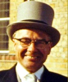
** Ted Barrs served his engineering apprenticeship during the 1920s, completing it alongside his best pal, Bill Day, who went on to found The North London Saw Works, at Waltham Cross - a business still running today (2014).
In 1931 Ted married and, with twin daughters born in 1935, moved to Beeston in 1942 to take up employment with Myford. Like most of his generation in senior engineering positions he was a hands-on man and, when his apprentices found a job too difficult, he would go down to the shop floor and demonstrate how it should be done.
Popular with both the owners (the Moore family) and with the workforce he rose to become Works manager. However, even after he retired he would spent many hours each week at the factory in an 'advisory' capacity - he really did live and breathe Myford machine tools.
Every year his young nephew Phillip, together with his father, I would go to the Model Engineering Exhibition in London, not only to see the models on display but, just as importantly, to see Ted. One visit Phillip spent an hour on the Myford stand learning woodturning from their demonstrator, a Mr. Fred Payne; "He taught me more about the craft in an hour than I would ever have learnt at school in a year."..
|
|
|
|
|
|
|
|
|
|
|
|
|
|
|
|
|
|
|
|
|
|
|
|
 |
|
|
|
|
|
|
Ted Barrs; designer of the Myford ML7 and ML8 and one-time works manager at Myford Engineering
|
|
|
|
|
|
|
|
 |
|
|
|
|
|
|
For many years the first Myford factory building - it had once been a lace works - was a landmark in Beeston, Nottingham. Unfortunately, years of machine-tool production had left the floor boards soaked in oil and it was finally condemned as unsafe by the fire brigade - and had to be demolished. This was probably no bad thing for Boxford's Factory, an old mill, was burnt to the ground some years ago - the oil-soaked flooring in that playing a major part in the ferocity of the blaze..
|
|
|
|
|
|
|
|
 |
|
|
|
|
|
|
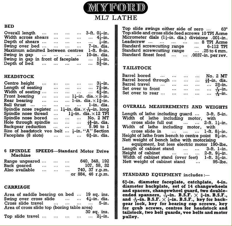
Specification sheet from the first comprehensive ML7 catalogue
|
|
|
|
|
|
|
|
 |
|
|
|
|
|
 |
|
|
|
|
|
|
|
|
|
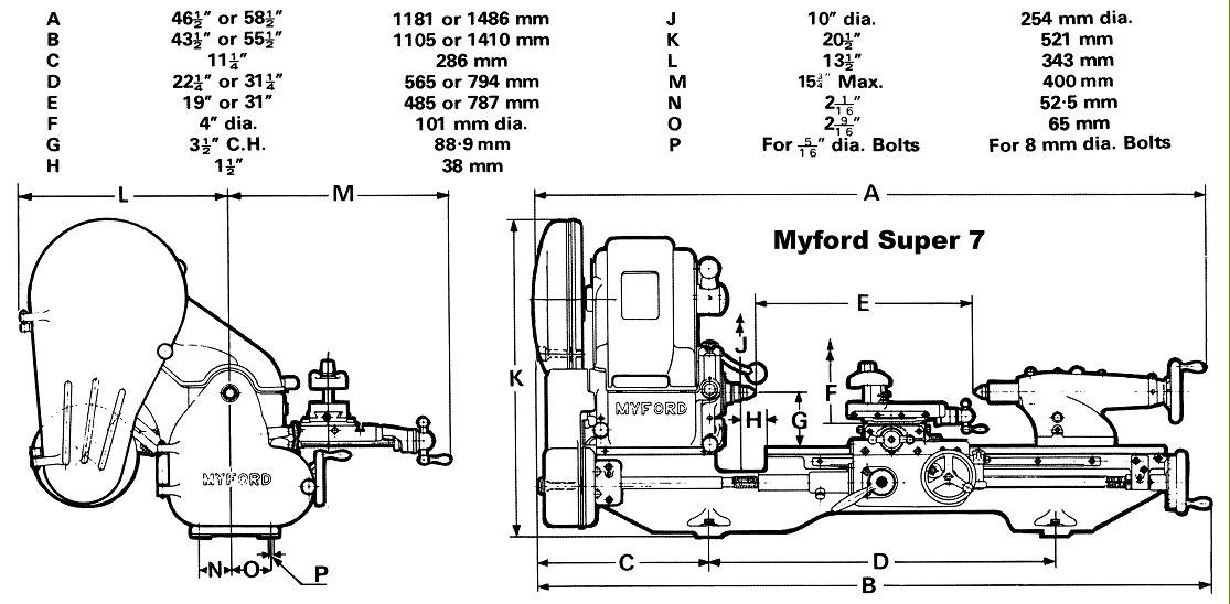
Dimensions: Myford Super 7 (although machine shown is from a late catalogue it's an early, pre 1959 version - through the differences are slight)
|
|
|
|
|
|
|
|
|
 |
|
|
|
|
|
|
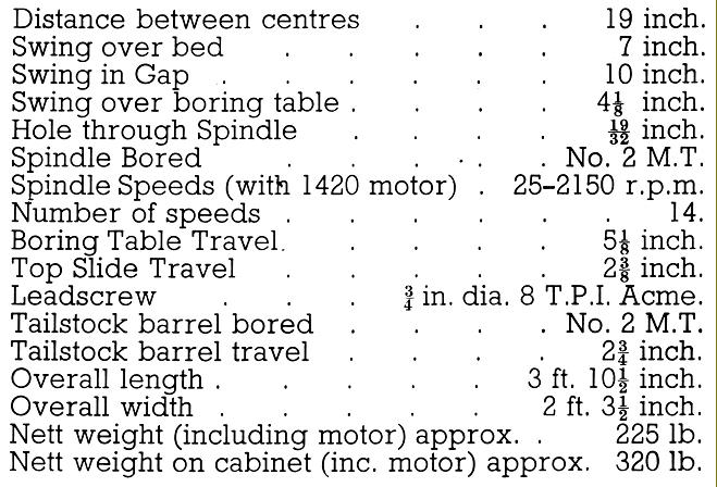
Above: specifications as given in the first Super 7 catalogue
|
|
|
|
|
|
|
|
|
|
|
|
|
|
|
|
|
|
|
|
|
|
|
|
|
|
|
|
|
|
|
|
The Best Ski School In Verbier & Zermatt - Switzerland
europeansnowsport.com
professionally-qualified staff - many native English speakers
VERBIER
28/07/2023
|
|
|
|
|
|