email: tony@lathes.co.uk
Home   Machine Tool Archive   Machine-tools Sale & Wanted
Machine Tool Manuals   Catalogues   Belts   Books  Accessories

MYFORD Screwcutting Gearboxes
- Mk.1, Mk. 2 and various third-party kit-built types -

Comprehensive Data Packs with Operation Manuals, Parts Lists
and Catalogues, etc., are available for most Myford lathes

Myford Home Page


1)  Myford ML7   
2)  Myford ML7 Tri-Leva   
3)  Myford Super 7 and ML7R
4)  Myford ML8 Wood lathe
5)  Myford ML10: (Modern 31/4" Lathe)       
6)  Myford 254, 254S and 254 Plus
7)  Myford/Drummond M Type   
8)  Myford ML1, ML2, ML3 & ML4: Pre-1947
9)  4-inch " Precision" Lathe: MF74 & MF32)
10) Myford Mini-Kop: (Hydraulic Copying)   
11) Myford Special & Capstan Lathes
12) Myford 280 Geared Head Lathe     
13) Myford Accessories
14) Myford Replicas and Clones
15) Serial Numbers
16) ML7 Rebuild

17) Early & 3rd-party screwcutting gearboxes
18) Myford ML7 photographic essay
19) Super 7B power cross feed photographs
20) Super 7 Plus (Big Bore) photographs
21) ML7R photographs
22) Rodney milling attachment
23) Amolco milling attachment
24) Staines & Big Swing Milling Attachment
25) Myford Milling Machines
26) Myford Super 7 "new in the box"
27)  Myford ML7 "new in the box"
28) Myford ML7R Photographs
29) First Myford ML7 Catalogues
30) ML2 Capstan - home conversion
31) ML2 Rebuild

32) Myford Shaper Attachment

Gearboxes and Screwcutting:
In standard form both lathes used changewheels for screwcutting and could generate (with the standard changewheel set) pitches from 6 to 112 t.p.i. (or 0.25 to 4 mm). However, both could be ordered (or retrofitted) with a screwcutting gearbox thus becoming, with the addition of a suffix to their model numbers, the ML7B and Super 7B. The gearbox generated 48 threads from 8 to 56 t.p.i. and the same number of feeds (by the simple expedition of pulling out a double gear mounted on the banjo) of  0.0139" to 0.002" per revolution of the spindle. Only an imperial box was ever offered, metric pitches being obtained by sets of  conversion changewheels. However, on  lathes sent to America (some found badges as the "
Allied AMCO 7" x 30" G", the gear cluster inside the box was modified, 23T gear replacing the 19T gear normally used - the result being that the box could generate North American pipe-thread pitches.
Although in the late 1940s a kit-form gearbox had been designed and marketed by L.H.Sparey (author of
The Amateur's Lathe) it was not until 1953 that Myford's first effort appeared. Lubricated by an oil-bath it was designed along long-established "Norton Quick-change" lines with a single-tumbler and a reversible gear on its left-hand face that allowed a change to be made between fine feeds and threads. Early boxes were fitted with unhardened gears and (hidden under a rounded, aluminium cover) a pair of external gears on the right-hand face (from which the leadscrew drive was taken) but in 1956, from box QC 2495 onwards, important alterations were made. Hardened gears were fitted and the leadscrew much better supported by being allowed to pass all the way through the box with the drive taken from its left-hand end - so allowing the external gears to be dispensed with. It is worth noting that the Metric Conversion Set for the early box is different - the four gears needed being: 2 x 60t, 1 x 44t and 1 x 52t. Later boxes required five gears: 2 x 60t, 1 x 50t, 1 x 45t and 1 x 63t. The standard Metric Conversion Set was replaced during the 1990s by a different design of slotted quadrant arm on which could be mounted a greater variety of changewheels - and so enabled the generation an almost unlimited number of English, Metric and odd threads and feeds. The Myford gearbox was a beautifully made and very tough unit and, with a supply of lubricant in its base (not something that every maker of small lathes considered important) very reliable. The only signs of wear one should encounter are in the shaft bushes; if the gears show signs of damage then the box must have been mishandled or denied lubrication; in normal use it is simply impossible to wear them out.
Supplied as standard with an ML7 or Super 7  the changewheel set comprised: 2 x 20, 25, 30, 35, 38, 40, 45, 50, 55, 60, 65, 70 and 75t. To cut a wide range of metric threads requires, in addition, just two 21t wheels. Myford Series 7 10 changewheels of all years are 20 D.P. with a 14.5-degree pressure angle, 3/8" thick with a 5/8" bore and 1/8" keyway.
A reproduction of the gearbox mounting template can be found below.
Third-party gearboxes include that offered by Sparey (writer of the well-known book The Amateur's Lathe) and a screwcutting conversion set (not a full gearbox) by Warrington Model Engineering Developments (WMED) called the "Easychange". This unit was intended to make the change from fine to screwcutting feeds quicker - and arranged, in effect, setting two trains of changewheels parallel to one another. The two sets were independent of one another and selected by a lever moving through a 3-position quadrant labelled Fine Feed, Neutral and Screwcutting. Details are at the bottom of the page.
Another box, the ALGOA, was designed by Hemmingway and Atham and, in its original form, had the main hosing made from fabricated parts. Plans and instructions to build the box are still available, with the box and lid available as castings. The internal gears are all standard Myford  20DP and all except a single 18t gear, can be adapted from standard changewheels. The box and lid can now be purchased as aluminium castings.
So far, only one screwcutting gearbox has been discovered for the Myford ML10 and Speed 10, this being by a Mr. Archibald and available in the form of plans from Hemmingway Kits


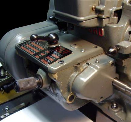
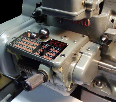
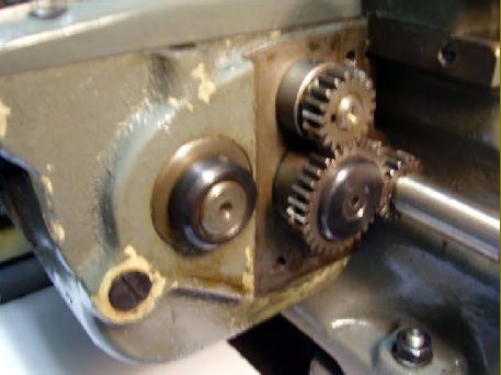
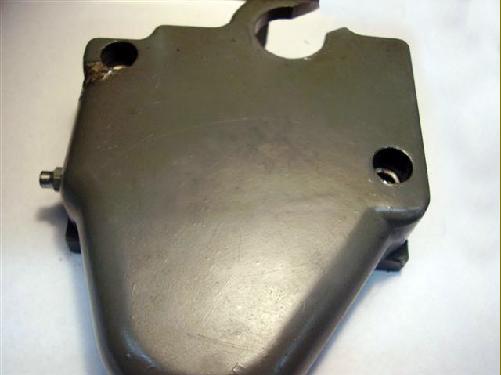
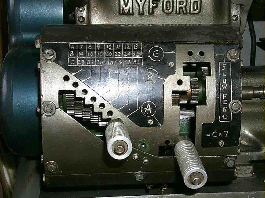
Although a kit-form gearbox had been designed and marketed in kit form during the late 1940s by L. H. Sparey (author of "The Amateur's lathe"), it was not until 1953 that Myford's first effort appeared. Lubricated by an oil-bath it was designed along long-established "Norton Quick-change" lines with a single-tumbler and a reversible gear on its left-hand face that allowed a rapid change between fine feeds and threads. The early boxes (as shown here) were fitted with unhardened gears and (hidden under a rounded, aluminium cover) a pair of external gears on the right-hand face (from which the leadscrew drive was taken) (later boxes had all the gears inside)
A data pack that includes the manuals for both gearboxes is available


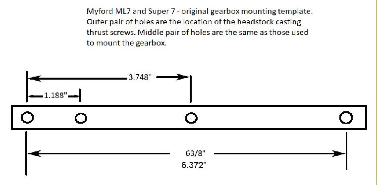
If an owner bought a gearbox kit for an early lathe a template was provided (Part No. 232) to help mark out the position of the holes that had to be drilled and tapped - on later beds these were already provided. The plate was secured to the tapped holes that held the screws used to push the headstock back against its alignment flange and holes drilled through the two centre holes such that they could be tapped 1/4" BSF. The maximum holes depth was 0.625" (though the right-hand hole may break through at that setting), the tapped length 0.500" and drill specified a 0.0204" (i.e. a No.6)

A gearbox drilling template in place

Designed in the late 1940s by L.H.Sparey, author of the indispensable book "The Amateur's Lathe" and a prolific writer on model engineering and model aero engines this screwcutting and feeds gearbox was produced in advance of Myford's own in 1953 - with a surprisingly large number appearing to have been constructed by enthusiastic owners. The box economised by using standard Myford changewheels. Later, the box was somewhat modified by David Machin with a cast aluminium casing and the introduction of a fine-feed assembly--though the latter has been found on some of the Sparey boxes. The magazine "The Model Mechanic" carried, in its March and April 1950 editions, articles about the construction of the box.

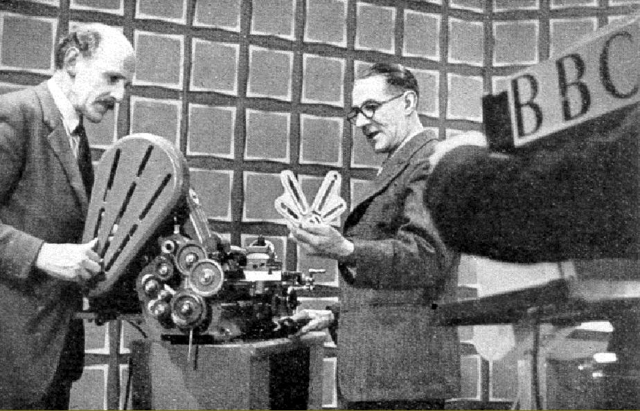
Featured on the BBC "Inventor's Club" programme during 1949. Sparey, right, demonstrates to  Geoffrey Baumfrey one of the modifications to his ML7 lathe


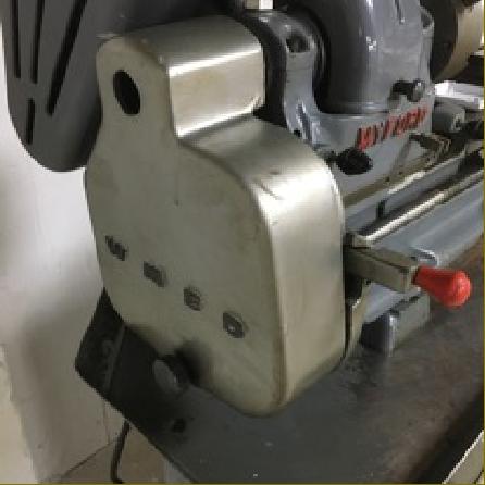
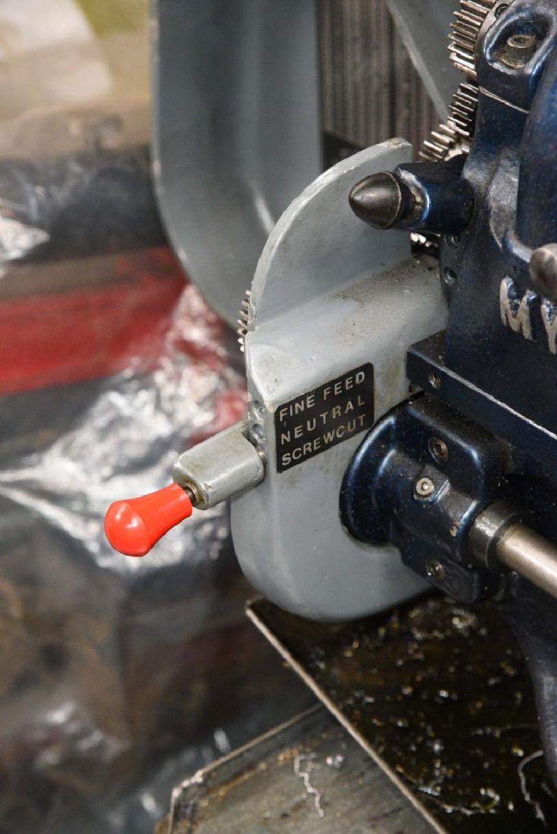
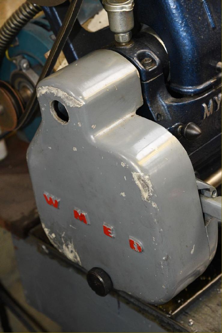
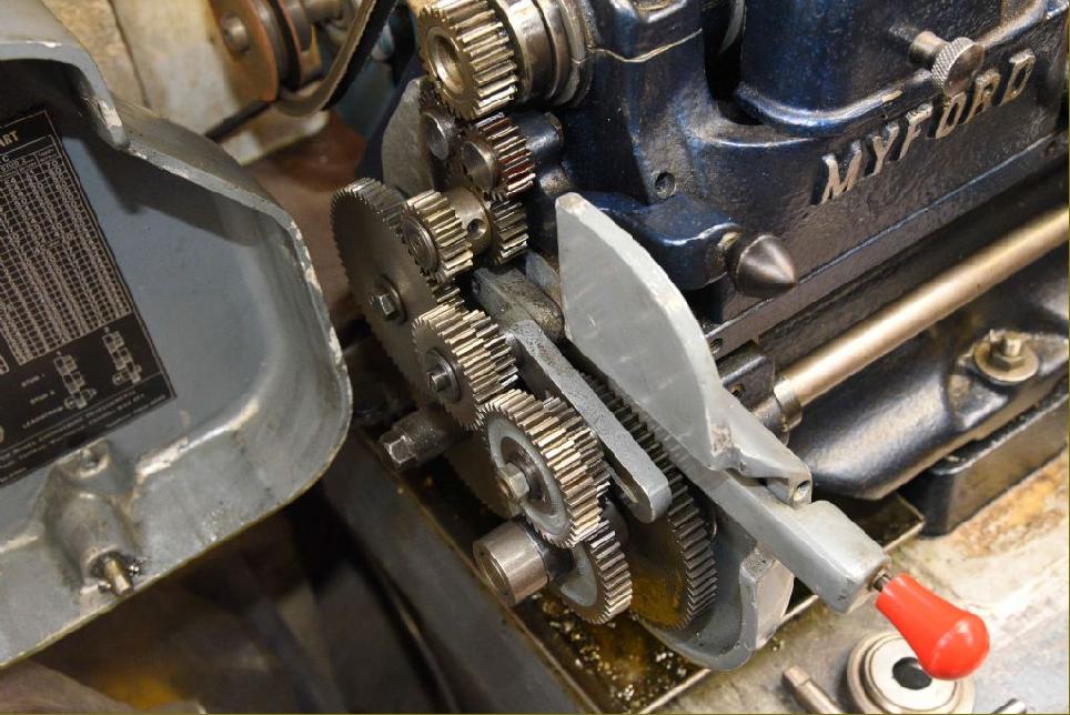
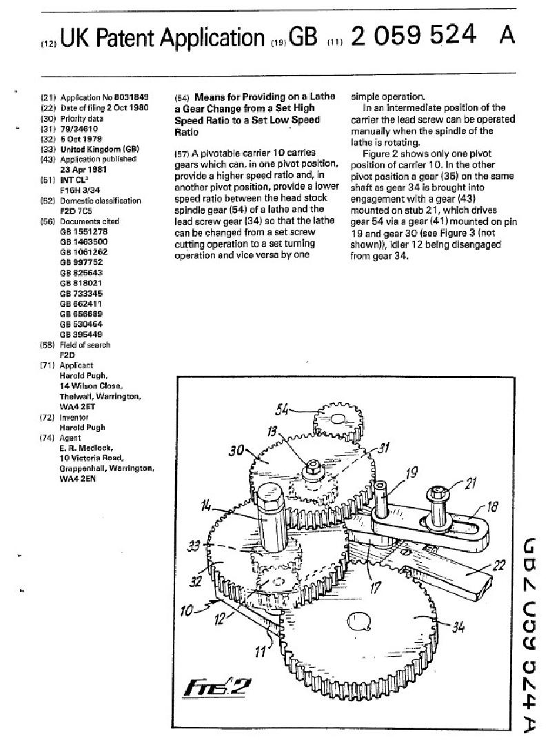
One very interesting screwcutting accessory for the Myford was that invented and patented by Mr. Harold Pugh whose company, Warrington Model Engineering Developments, also manufactured a power cross feed attachment.
Called the "Easychange", the screwcutting unit was intended to make the change from fine to screwcutting feeds quicker - and arranged, in effect, setting two trains of changewheels parallel to one another. The two sets were independent of one another and selected by a lever moving through a 3-position quadrant labelled Fine Feed, Neutral and Screwcutting.
The WMED attachment was a thoroughly well-engineered affair with its own cast cover, the inner section of which had its front face drilled to locate the change-over lever.
The arrangement of the Easychange has some similarity with that used on the far more complex and unusual Cromwell Mk.2 precision lathe where, at the headstock end of the lathe, one fixed-ratio gear train was enclosed in a housing and used for power feeds while the other was carried externally - and unprotected - and employed only for screwcutting. 


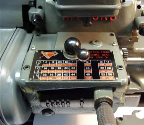
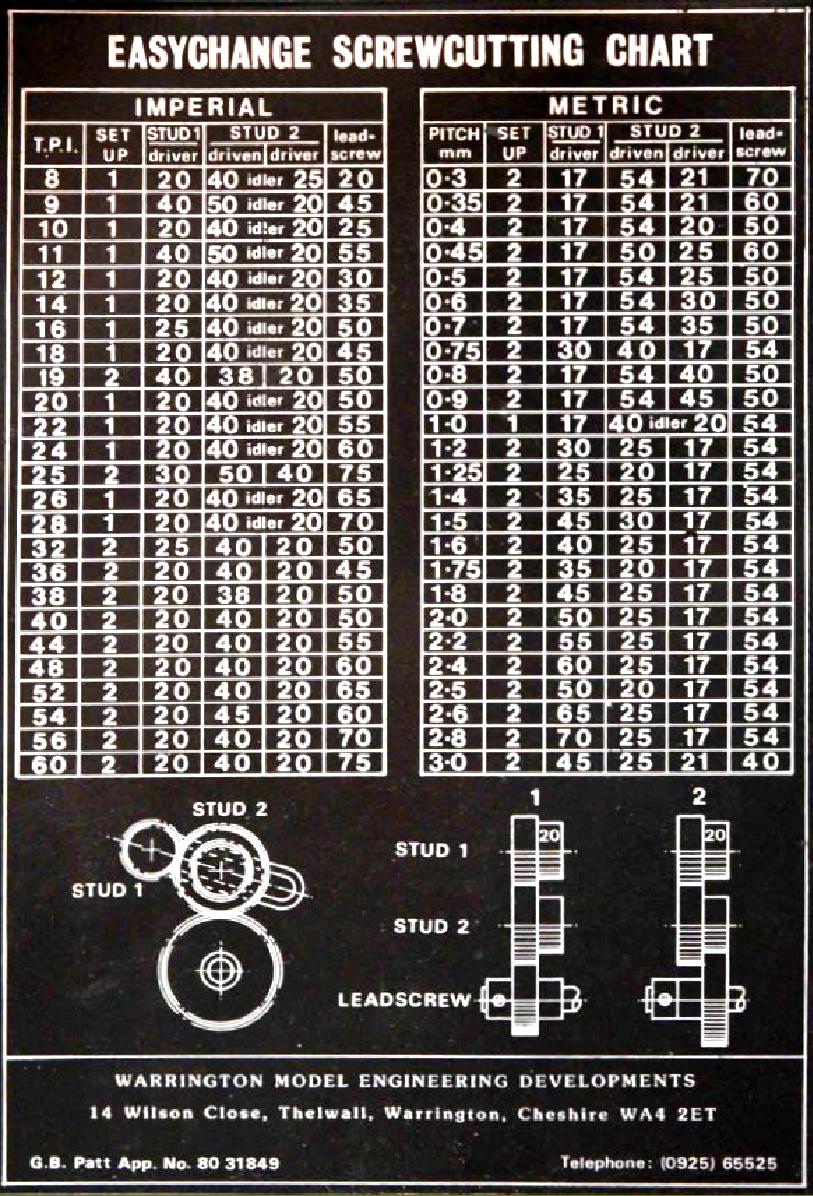
The Easychange screwcutting chart differed from the Myford original, with the relative complexity of the unit limiting the combinations of changewheels that could be mounted.

MYFORD Screwcutting Gearboxes
- Mk.1, Mk. 2 and various third-party kit-built types -
Myford Home Page 

Comprehensive Data Packs with Operation Manuals, Parts Lists

1)  Myford ML7   
2)  Myford ML7 Tri-Leva   
3)  Myford Super 7 and ML7R
4)  Myford ML8 Wood lathe
5)  Myford ML10: (Modern 31/4" Lathe)       
6)  Myford 254, 254S and 254 Plus
7)  Myford/Drummond M Type   
8)  Myford ML1, ML2, ML3 & ML4: Pre-1947
9)  4-inch " Precision" Lathe: MF74 & MF32)
10) Myford Mini-Kop: (Hydraulic Copying)   
11) Myford Special & Capstan Lathes
12) Myford 280 Geared Head Lathe     
13) Myford Accessories
14) Myford Replicas and Clones
15) Serial Numbers
16) ML7 Rebuild

17) Early & 3rd-party screwcutting gearboxes
18) Myford ML7 photographic essay
19) Super 7B power cross feed photographs
20) Super 7 Plus (Big Bore) photographs
21) ML7R photographs
22) Rodney milling attachment
23) Amolco milling attachment
24) Staines & Big Swing Milling Attachment
25) Myford Milling Machines
26) Myford Super 7 "new in the box"
27)  Myford ML7 "new in the box"
28) Myford ML7R Photographs
29) First Myford ML7 Catalogues
30) ML2 Capstan - home conversion
31) ML2 Rebuild

32) Myford Shaper Attachment