|
Continued:
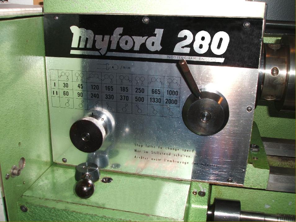
Totally enclosed against the ingress of dirt and shavings the screwcutting gearbox contained hardened and ground gears running in a splash oil bath - a sight glass being provided on the front face of the box to check the level. The metric box (working in conjunction with a 3 mm pitch leadscrew) could produce 26 pitches from 0.2 to 4 mm and the imperial (leadscrew pitch 1/8") 25 threads from 8 to 64 t.p.i. ( 1/64" to 1/4"). A total of 32 metric feed rates were available from 0.05 to 1.33 mm sliding and 0.017 to 0.44 mm surfacing. The 50 rates of inch feed spanned 0.002 to 0.042" sliding and 0.0007 to 0.014" surfacing (all per single revolution of the spindle). Control of the gearbox was by an 8-position (metric) or 9-position (imperial) numbered dial on the front face in conjunction with a spring-loaded lever to release and lock its setting, a 3-position lever on top of the box and a reversible double-gear cluster in the changewheel train (just like that employed on the Series 7 lathe gearbox) that gave fast and slow input speeds and hence an easy switch between coarse screwcutting and fine power feeds (for correct operation of the box reference to the Instruction book is essential). The changewheel drive to the gearbox was through a tumble-reverse mechanism - contained within the headstock, where it benefited from the headstock oil bath - and could be arranged with either a metric/imperial or imperial metric conversion set, or alternative gears to give additional pitches. An easily-changed shear pin, positioned through the leadscrew just outboard of the screwcutting gearbox, protected the gear-train drive. By the late 1970s the customer could specify changewheels in a non-metallic material to reduce noise and the need for lubrication.
With an oil supply in the base (distributed by splash) the double-walled apron was fitted with a pair of conventional half-nuts (running in adjustable gibs) to engage the leadscrew. Power sliding and surfacing feeds were selected by a push-pull knob ("in" for sliding feed and "out" for surfacing with neutral between) and engaged by lever-operated clutch that incorporated a spring-loaded torque limiter to protect the mechanism against damage by overload. A thoughtful touch was the provision of a large zeroing micrometer dial on the carriage handwheel. As a very useful extra (and to compliment the standard-fit, saddle-activated motor cut-out switch on the 280-EM and 280-EI) the lathe could be fitted with an automatic disengage system to the carriage longitudinal feed; this was operated by a long bar running the length of the bed that carried four individually adjustable stops. Unfortunately the disengagement mechanism only worked in one direction - towards the headstock.
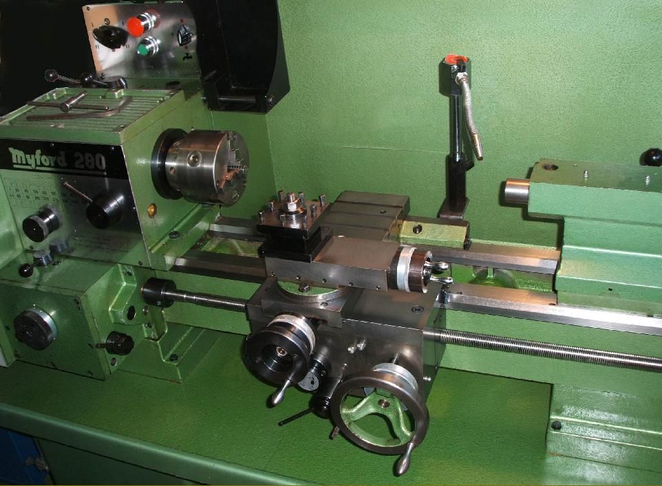
Unlike so many lathes of a similar size that used a short, plain cross slide that on the 280 was both full length (to even out wear) and carried 4 T-slots behind the 360-degree swivelling top slide. Both zeroing micrometer dials were large and easily read (and could be supplied as dual inch/metric units) with a non-glare satin-chrome finish. Though few customers can have chosen it - preferring instead a 4-way or quick-set unit - the standard toolpost was the one from the Myford 7-series, a simple triangular clamp with self-aligning "wobble" washer. Unusually, to let the top slide swivel round to 90-degrees, the full-circle cross-feed handwheel rim could be removed.
With a ball-race thrust bearing and 3-inch graduated scale the tailstock barrel carried a sensible No. 3 Morse taper socket that allowed really heavy drilling to be undertaken. The tailstock could be set over on its sole plate for taper turning but, unfortunately, the feed handwheel was not fitted with a micrometer collar.
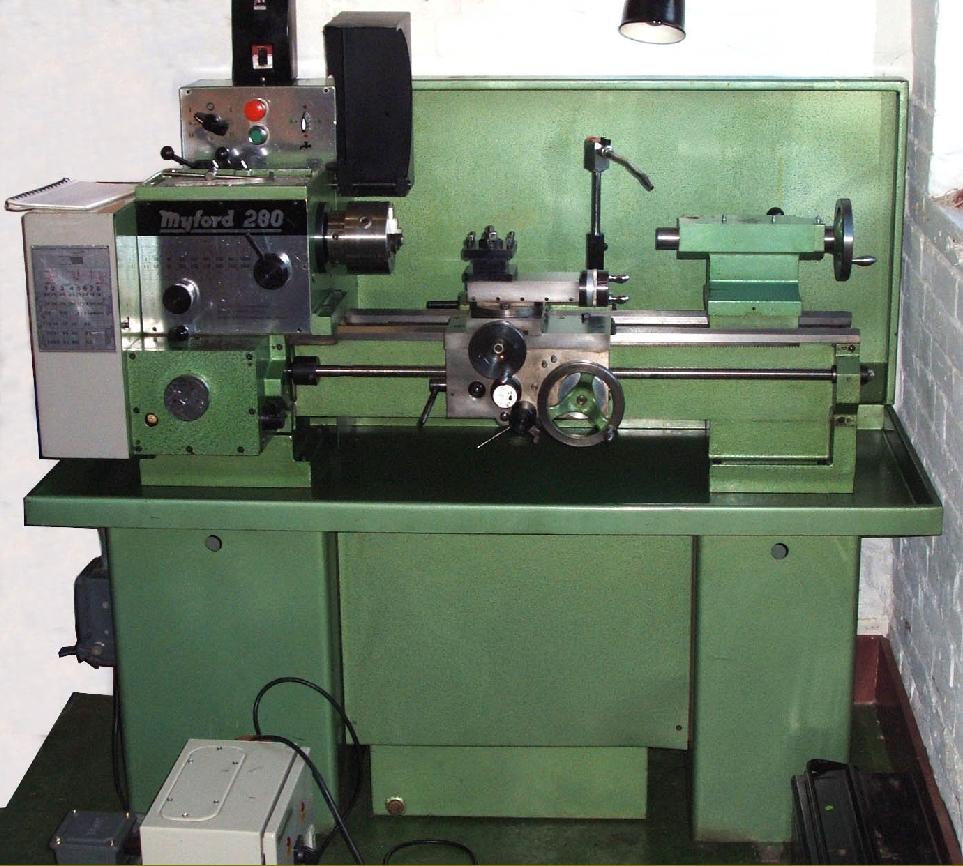
Electrical fittings varied with early machines having a switch box mounted at the rear of the headstock and later models an improved self-contained enclosure fastened to the front edge of the chip tray at the headstock end of the stand. The usual type of "no-volt" push-button starter was fitted, to prevent the machine restarting after a power cut, and an emergency stop button and a low-voltage control circuit also provided.
An owner's story:
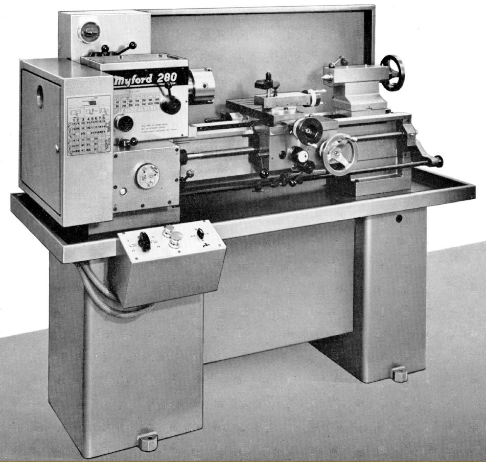
In late 1985 the question of a replacement for my Myford Super 7 arose. The criteria was at least a 5" centre height, an all-geared head and a V-way bed. Several lathes were examined, including Denford, Boxford, Myford, Harrison and the recently resurrected and redesigned Holbrook. The choice was eventually narrowed down to the 280 and the Harrison; the latter was a more pleasing design than the 280, but appeared to be of lighter construction - but the clincher came with the position of the saddle handwheel. On the Harrison this was on the left - and I can still recall from my apprenticeship days the shower of brass and red-hot gunmetal chips directed on to the backs of my hands. Having chosen the 280 I contacted Myford only to find they had discontinued manufacture. However, they had one metric 3-phase 280 left in stock and I attempted, over several weeks, to have this converted to Imperial form and single-phase electrics, I think must have become fed up with me pestering them because they eventually, to my disappointment, announced it had been sold. To help, they suggested that I contact Trevor Whiting, an ex Myford employee who had started a machine-tool business. I spoke to Trevor, who told me that, to his knowledge, Myford had enough parts to build one more 280, and said to leave it with him. Amazingly, Trevor persuaded them to make one and it was delivered to me on 26th July 1986. The lathe as delivered is shown in the copy of the brochure, 280P1..
|
|