|
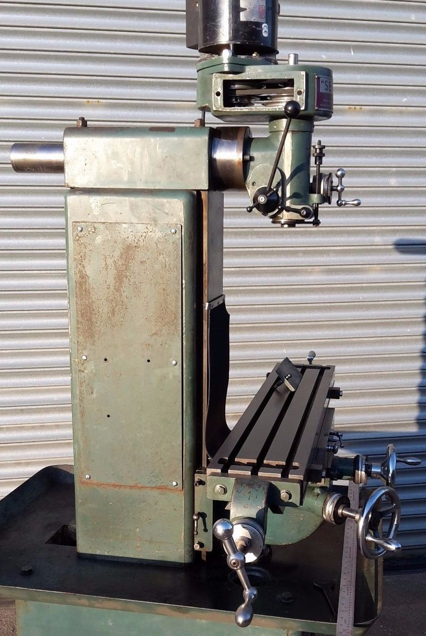
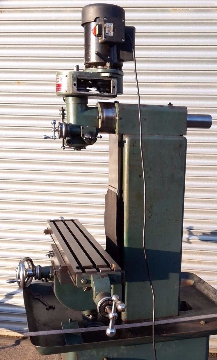
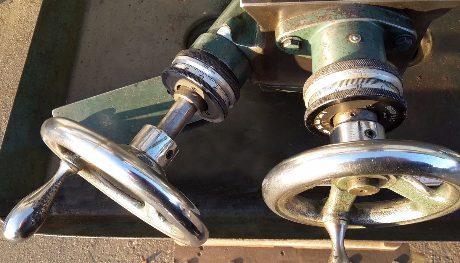
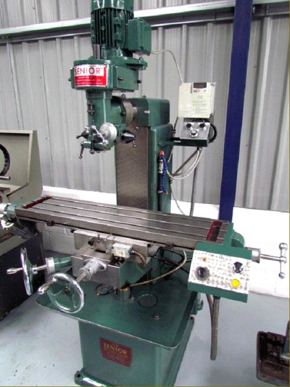
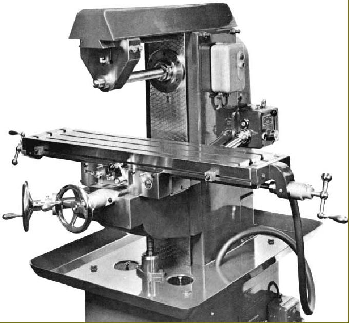
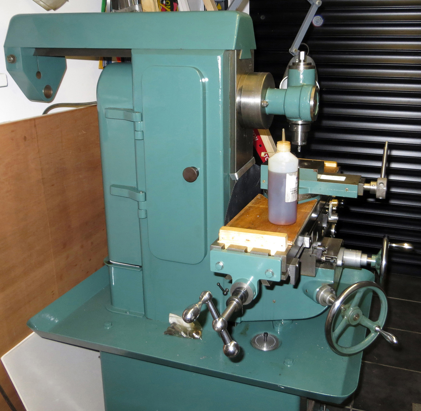
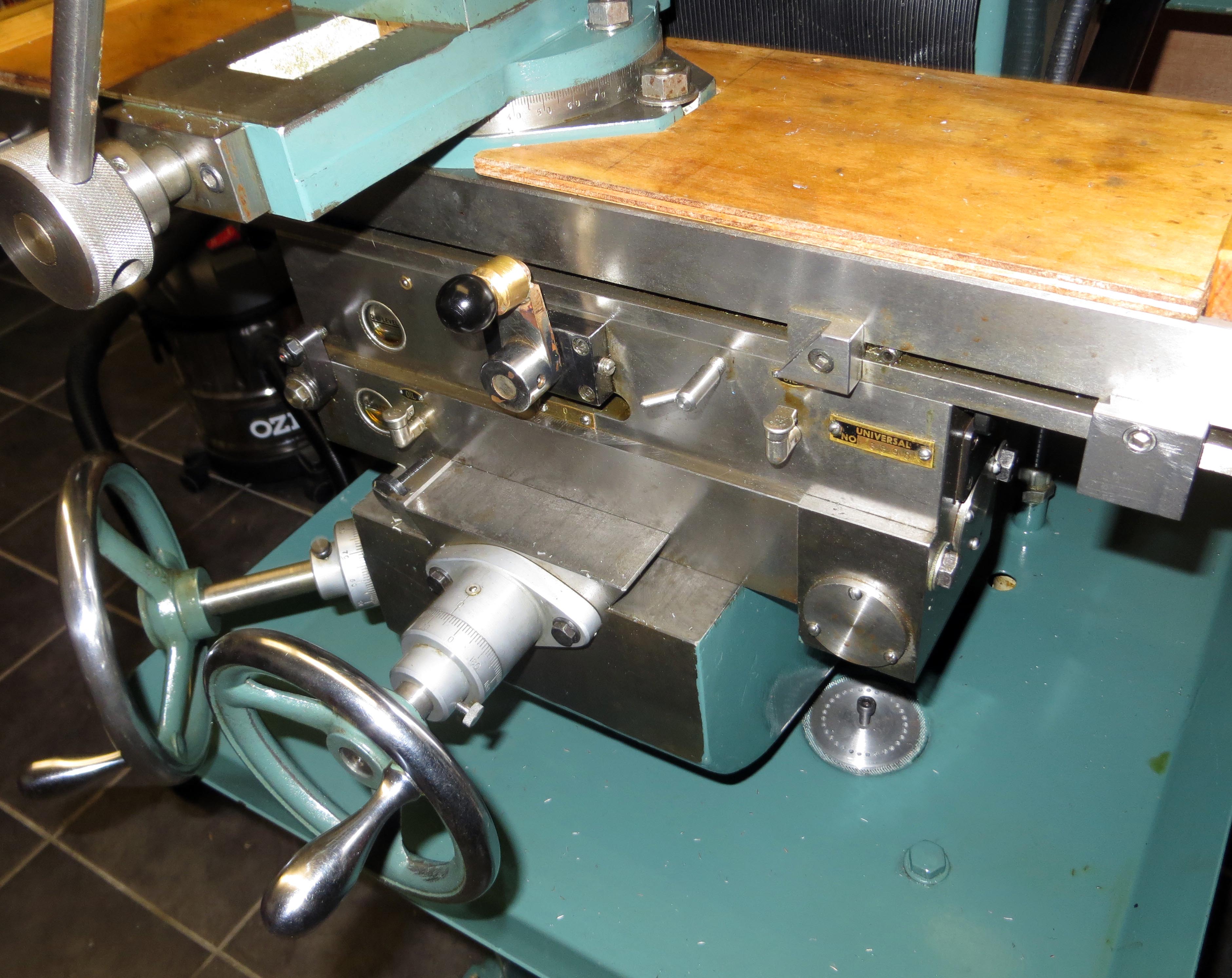
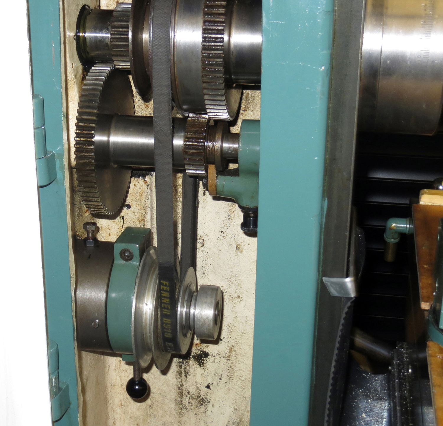
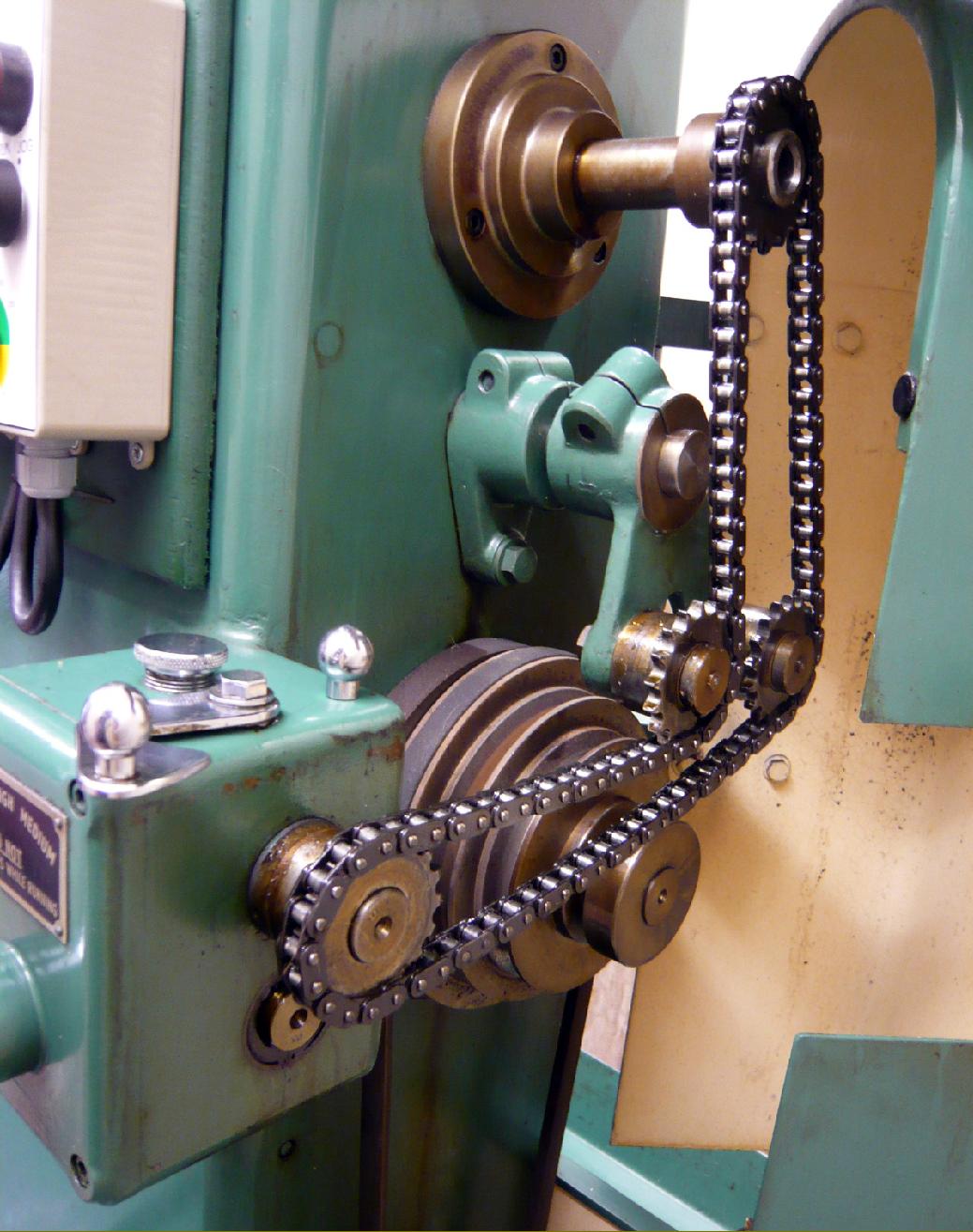
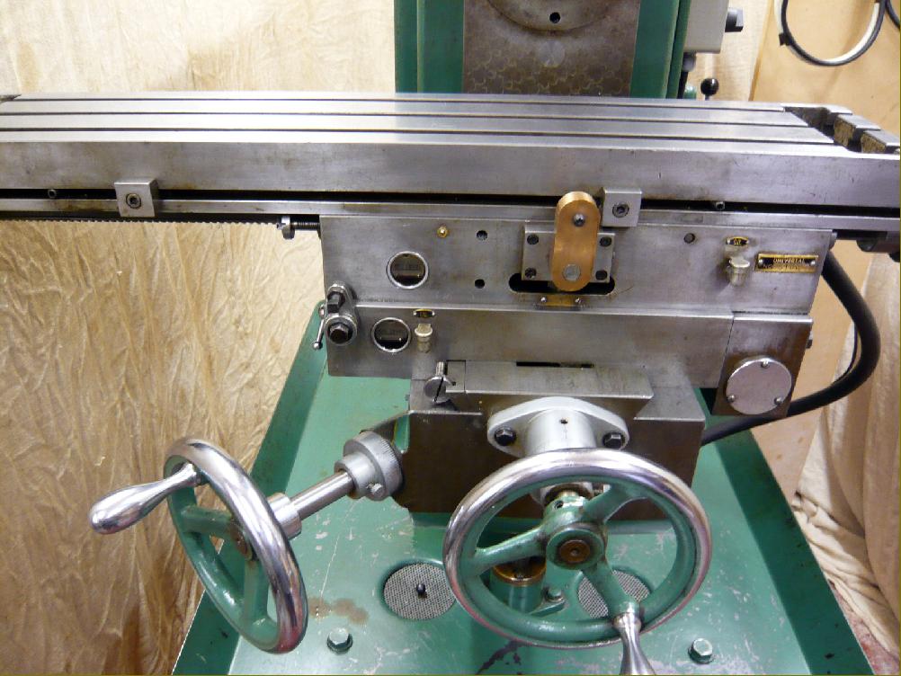
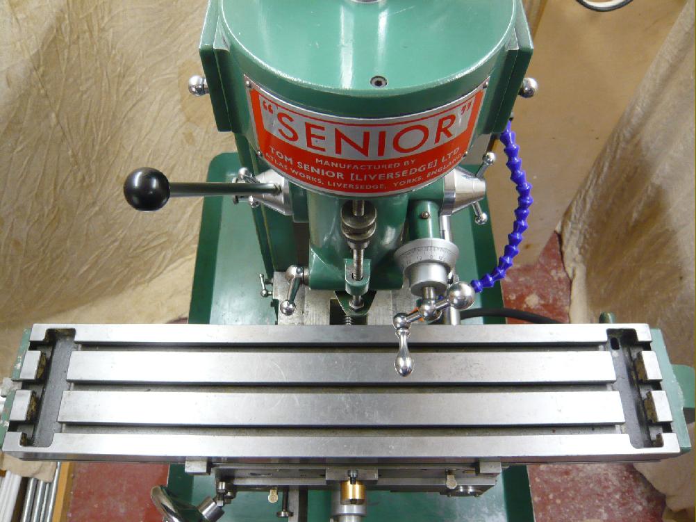
Home Machine Tool Archive Machine-tools Sale & Wanted Tom Senior Model "Major ELT" Instruction Books and Catalogues are available for the Senior range Tom Senior Older Millers Standing for Extra Long table the Major ELT ( a variant of the dovetail overarm "V.S.") was a top-of-the-range model that included a number of enhancements and modifications to improve its performance and accuracy. Alterations included a dovetail overarm socketed into the top of the main column (replacing the less satisfactory round type), an extra long, 37" x 8.5" table with 28" of longitudinal travel, a knee of increased size and rigidity and, at 9", a cross feed some 2" longer than any previous Senior miller. Instead of a belt drive to table's power-feed gearbox a chain was used, this improving the machine's metal-removing ability when using a slab cutter A very expensive - and hence rare - version of the ELT was available with a swing table (thus making it a truly "Universal" model) - though this version is sometimes found with the standard not extended table. Like the Standard "Major", the ELT had the internal reduction gears, these giving twelve speeds on the horizontal spindle from 50 to 1600 r.p.m. and allowing deep cuts to be taken when using the horizontal mode. One expensive option was the self-contained, belt-driven "S-Type" vertical head, this being fitted to the end face of the dovetail overarm. Beautifully built, the S-Type head used a 0.5 h.p. motor (1-phase or 3-phase) with drive by a Z-section V-belt to a spindle whose 2.5-inch travel quill was equipped with both fine and quick-action drilling feeds - the former being engaged through a cone clutch, exactly in the manner used on the Centec vertical head.. The spindle ran in precision-class Timken taper roller bearings (with a needle roller bearing at the tail) with early machines having four speeds from 480 to 2760 r.p.m. on a 3-phase supply and from 500 to 2,800 on 1-phase. Later versions had six speeds (though with the same speed range) - or a very effective electronic infinitely-variable speed drive unit. However, the option was available of a slower-running motor - 950 r.p.m. - though few can have been sold. Simple but effective snap-on covers at each side of the head guarded the belt run - though simple the mechanism was far from cheaply constructed, with spring-loaded balls held within bronze housings. |
|
|
||
|
|
||
|
|
||
|
|
||

|
|
||


|
Senior Home Page Senior Lathes Senior Shapers & Planers Price List Home Machine Tool Archive Machine-tools Sale & Wanted
|