 |
 |
 |
 |
 |
 |
 |
 |
 |
 |
 |
 |
 |
 |
 |
 |
 |
 |
 |
 |
 |
 |
 |
 |
|
|
|
|
|
|
|
|
|
|
|
|
|
|
|
|
|
|
|
|
|
|
|
|
|
|
email: tony@lathes.co.uk
Home Machine Tool Archive Machine-tools for Sale & Wanted
Machine Tool Manuals Machine Tool Catalogues Belts
Books Accessories
Hendey
Lathes of the 1920s & 1930s
14-inch & 24-inch Geared Head
Cone-head 12 to 16 inch Cone-head 18 to 24-inch Taper Turning
Slide Rests Relieving Motor Drives
New-type, Mid-1930s Geared-head Lathe Accessories
|
|
|
|
|
|
|
|
|
|
|
|
|
|
|
|
|
|
|
|
|
|
|
|
Although flat-belt drive lathes can be astonishingly smooth running - and produce amazingly-good surface finishes - their ultimate metal-removal ability is limited by the amount of power the belt can transmit. So long as cutting tools were only slightly harder than the metal they were working, this was not of too great a concern, but as better qualities of carbon (and finally tool-steel) became available, and metal-removal rates began to climb, the limits of flat-belt power transmission were quickly reached. Although engaging backgear helped and some lathes (the US makers Harrington and Hamilton amongst them) were double and even triple backgeared - this reduced spindle speeds below those desirable for optimum results; it was obvious that the limits of the system, had been reached and a radical solution was called for - the fully-geared headstock. Unfortunately, one of the problems with geared-head lathes is their propensity, especially when worn, to leave fine "vibration" marks in the turned surface; although often lost in the "roughness" of commercial turning - or in rough turning done prior to grind finishing - such marks become increasingly obvious when the machine is of sufficient quality to generate a particularly smooth finish. It was quickly realised that for the best possible results it would be necessary to isolate the headstock from as many connections with a gear drive as possible - and so the concept of a remotely-mounted gearbox was developed.
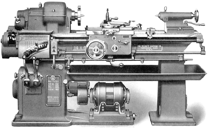
One of the earliest attempts at this type of construction was made by Hendey with their 14-inch E.C.M. (Enclosed Chain Motor Drive) Engine Lathe. The means of changing the spindle speed was (apart from backgear) removed from the headstock and built into a separate gearbox (pivoted for chain-adjustment purposes) within the headstock-end cabinet leg. The box contained nine hardened alloy-steel gears, sliding on three hardened and ground shafts, all running in an oil bath and with the speed changed by two ball-ended levers positioned on the front face of the cabinet leg just below the screwcutting gearbox. Nine speeds were provided - doubled to 18 with the headstock-mounted backgear - from 15 to 407 rpm. The last shaft in the box carried a sprocket for 2-inch wide "silent-chain drive" which ran up the headstock spindle. Because the spindle had to carry only a backgear and sprocket for the chain drive, its construction, and that of its surroundings was greatly simplified.
|
|
|
|
|
|
|
 |
|
|
|
|
|
|
1920s Hendey 14-inch E.C.M. Motor Driven Engine Lathe.
|
|
|
|
|
|
|
|
|
|
 |
|
|
|
|
|
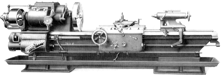
Hendey 24-inch Geared-head lathe
The spindle had nine speeds - typically from 10 to 320 rpm - three through gearing carried on the spindle, and six through double back gears.
The 1.75-inch bore spindle, threaded 4-inch x 3 t.p.i, was manufactured from a high-carbon, hammered steel forging, and finished to what was described as "scleroscope-hardness". The spindle was bored for a No. 6 Morse taper sleeve, and normally ran with a No. 5 Morse centre in place.
The spindle ran in tapered, plain bearings, each lubricated with a "ring oiler", and with its own adjustment to minimise the effects of contraction and expansion as the work load varied throughout the day - yet without disturbing the running adjustment.
The spindle end thrust was taken on the face of front bearing through a hardened and ground steel collar interposed between face of hearing and spindle collar; once the end-thrust adjustment had been made it should have remained constant over a long period of service - any wear in the taper bearings and spindle being adjustable by a simple resetting of a collar nut. The headstock was lubricated by the simple means of the lower gears dipping into the oil, and flinging it around inside the casing. A simple friction clutch was fitted to the headstock drive, controlled by two levers, one directly below the headstock the other carried on the bottom of apron.
Able to generate 36 different English threads and feeds the screwcutting gearbox was available with extra gears available to cut metric and other threads not listed on the plate. An automatic stop was fitted - which worked in both directions for both screwcutting and feeds - this was a feature of all later Hendey lathes - but one which the handbook cautioned against using (on these early models) at higher speeds..
|
|
|
|
|
|
|
|
 |
|
|
|
|
|
|
Early-pattern Hendey geared headstock. To change speed the spindle was stopped and lever A moved to its OUT position. Lever B could then be turned across its quadrant to select the desired speed. The "backgear" on this headstock ran in permanent mesh with the spindle, and was engaged and disengaged through a dog clutch operated by the lever C.
|
|
|
|
|
|
|
|
|
|
|
|
|
|
email: tony@lathes.co.uk
Home Machine Tool Archive Machine-tools for Sale & Wanted
Machine Tool Manuals Machine Tool Catalogues Belts
Books Accessories
Hendey
Lathes of the 1920s & 1930s
14-inch & 24-inch Geared Head
Cone-head 12 to 16 inch Cone-head 18 to 24-inch Taper Turning
Slide Rests Relieving Motor Drives
New-type, Mid-1930s Geared-head Lathe Accessories
|
|
|
|
|
|
|
|
|
|


