 |
|
|
|
|
|
|
|
|
|
|
|
|
|
|
|
|
|
|
|
|
|
|
|
|
|
|
|
|
|
|
|
|
|
|
|
|
|
|
|
|
|
|
|
|
|
|
|
|
|
|
|
|
|
|
|
|
|
|
|
|
|
|
|
|
|
|
|
|
|
|
|
|
|
|
|
|
|
|
|
|
|
|
|
|
|
|
|
|
|
|
|
|
|
|
|
|
|
|
|
|
|
|
|
|
|
|
|
|
|
|
|
|
|
|
|
|
|
|
|
|
|
|
|
|
|
|
|
|
|
|
|
|
|
|
|
|
|
|
|
|
|
|
|
|
|
|
|
|
|
|
|
|
|
|
|
|
|
|
|
|
|
|
|
|
|
|
|
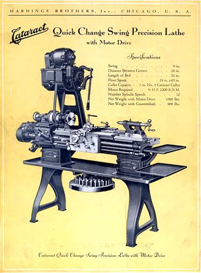
Designed personally by Mr. Franklin Hardinge - and in production for the first time during WW1 (1914 -1918) - the fabulous Hardinge 9" x 28" "Cataract Quick-Change Swing Precision Lathe" was a new departure for the company. Built in very limited numbers - it is though that only three-hundred or so were sold - today 45 have been located with the serial numbers jumping from a 3-digit form at No. 334 to a 4-digit at 5789. The highest number so far found is 7374 with some evidence existing that production might have continued until as late as 1928. The earliest-known survivor is No.6 and the last example to emerge, No. 136, was found in England during 2017.
As standard the lathe's capacity was, considering the enormous depth, width and weight of the bed, very modest but, as its name implied ("Quick-Change Swing"), it was possible to make better use of its strength and order a set of raiser blocks for headstock, tailstock and toolpost that took the centre height from 4.5 to a more useful 7.5 inches. These blocks (they are very rare) were missing from an example owned by the writer some years ago (date stamped 1917), a machine that had been standing neglected for many years; although superficially in poor order, the quality shone through and with just a thorough clean, careful oiling and attention to the main adjustments it was successfully restored to active and accurate duty.
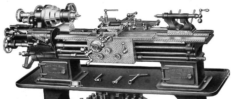
With an excellent general specification there were, amongst other delights, an enormously deep and wide bed, a carriage with immensely long wings and a 21/32-inch diameter front headstock bearing carrying a massive, well-supported, hardened and ground 1.25" bore spindle with a 23/16" x 10 t.p.i. Thread. The inside of the spindle takles standard 5C collets - a fitting that was to become rather popular. However, although the catalogue specification was for a 5C, it's entirely possible that lathes might have been supplied with alternatives - for example, a customer with a large collection of 4C collets might have ordered that fitting instead (the 4C has a body diameter of 0.95", a length of 3.00, not including the domed portion and a 15/8" x 10 t.p.i. thread; the 5C spindle thread is 23/16 x 10 t.p.i.
Hardinge obviously went to an enormous amount of trouble with the design and patented not only the whole lathe (in so far as that could be done) but also each significant individual feature, including the quick-change screwcutting and feeds gearbox, the carriage and apron-feed mechanism, headstock bearings and ball bearing/thrust adjustment--and even the collet carousel (searching US Patents using the Google system will reveal most of the details). One useful fitting (continued until the present day on the Hardinge HLV-H lathe) was a quick withdrawal mechanism whereby the top slide could be instantly disengaged from a screwcutting job even with the spindle running at high speed. The original spoked, cast-iron backgears were perhaps on the fragile side - they have been known to strip - but this was the lathe's only known weak point. A full screwcutting gearbox was fitted and drove a 1-inch diameter 6 t.p.i leadscrew with a separate powershaft for the standard-fit power sliding and surfacing feeds (both engaged by safety-overload friction clutches) with an automatic, precision-adjustable disengagement to the sliding feed. Extremely long saddle wings overlapped the front and back of the headstock by several inches - giving improved support to the cutting tool when brought up to the spindle nose. Taper turning (with fine-screw adjustment of the setting) was fitted as standard; the top slide could be swivelled through 360° (just one square-headed bolt required slackening first); twin-bolts clamped the tailstock in place and a useful swing-out rotating collet tray was fitted beneath the chip tray. To improve productivity and the finish on work, the operator was encourage to use the right rate of feed (three being available for each setting of the gearbox) just a single control lever, which worked through the gearbox input gears, being used to make the change.
It appears that the Cataract Quick-Change Swing lathe inspired Mr. Edgar Holbrook to produce the very similar Model B No.9, a lathe with an identical bed, the same quick-withdrawal mechanism on the top slide and also, it is believed, a 5C collet fitting in the headstock spindle..
|
|
|
|
|
|
 |
|
|
|
|
 |
|
|
|
|
|
|
|
|
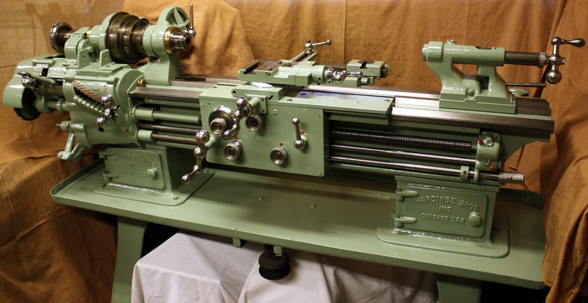
Hardinge Cataract "Quick Change 9-inch swing Precision Lathe" with its unusual and distinctive storage cupboards built into both the headstock and tailstock bed feet
|
|
|
|
|
|
|
|
|
|
|
 |
|
|
|
|
 |
|
|
|
|
|
|
|
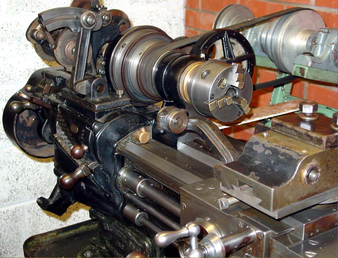
A swing-out, rotating collet tray was fitted as standard. The lever marked "N" in
the picture is the top slide quick-withdrawal control
|
|
|
|
|
|
|
|
|
|
|
|
|
|
|
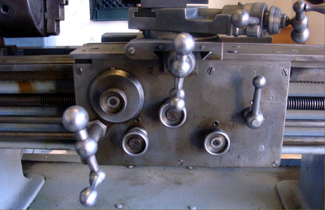
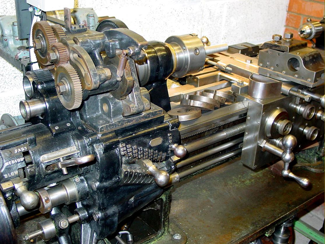
Detail of the headstock and screwcutting & feeds gearbox control levers
|
|
|
|
|
|
|
|
|
|
|
|
|
|
 |
|
|
|
|
|
Based on the bed used for the Cataract Quick-Change Swing Precision, the Turret Tool Post Lathe was designed for the precision production of work associated with optical parts - especially lens mountings and other jobs where several operations on delicate materials involving turning, boring, recessing and internal and external threading had to be done on one undisturbed setting. Threading was by a headstock-mounted chasing unit with an independently-adjustable double tool head that allowed internal and external threading to be done on one setting whilst each of the six tools in the cross-slide mounted turret was independently adjustable for "diameters and lengths". The headstock bearings were equipped with oil reservoirs with feed by wicks.
|
|
|
|
|
|
|
|
|
|
|
 |
|
|
|
|
|
|
|
|
|
|
|
 |
|
|
|
|
|
|
|
|
|
|
|
 |
|
|
|
|
|
 |
|
|
|
|
|
|
A well-preserved Quick-Change fitted with the rarest accessory of all--a relieving attachment
|
|
|
|
|
|
|
|
 |
|
|
|
|
|
|
Another view of the Hardinge Cataract Quick-Change lathe's relieving attachment
|
|
|
|
|
|
|
|
 |
|
|
|
|
|
|
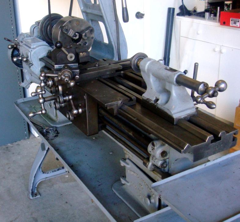
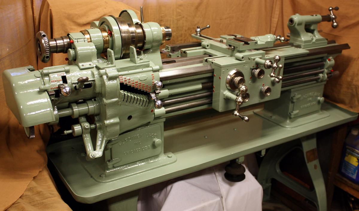
A recently restored Cataract Quick-change Swing Toolroom lathe dated 1917. Note the enormous depth of the bed. This particular example was rebuilt in England during 1950 by the machine-tool makers Cravens. The restoration was comprehensive for, instead of replacing the original and perhaps fragile straight-cut cast-iron backgears with other of the same design (the originals have been known to strip) they were replaced by ones of a helical form - and with those on the spindle in bronze. As part of the re-engineering, the whole inside of the main pulley was modified as well, with the small bronze backgear extended to form a sleeve bearing on which the pulley could turn. Unmodified examples of the lathe do not have the cut-outs in the pulley flange for the retention screws holding the bronze insert in place. The back gear actuation handle (cut down on the example above) would normally have been on the rear back gear lug, not at the front as shown. In addition to the pictures on this page, more of this machine are here
|
|
|
|
|
|
|
|
|
|
|
|
|
|
 |
|
|
|
|
|
 |
|
|
|
|
|
|
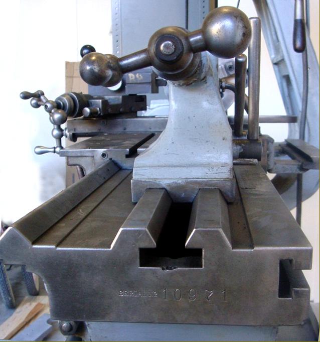
Bed section. The carriage ran on a single V at the front and a flat at the back. The tailstock (and headstock ) were aligned on a central bevelled-edge way
|
|
|
|
|
|
|
|
 |
|
|
|
|
|
 |
|
|
|
|
|
|
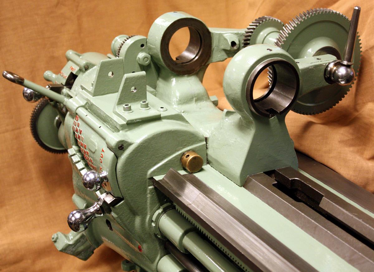
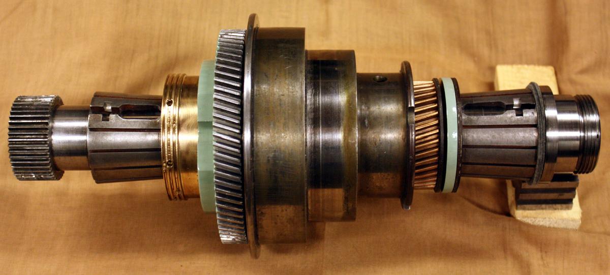
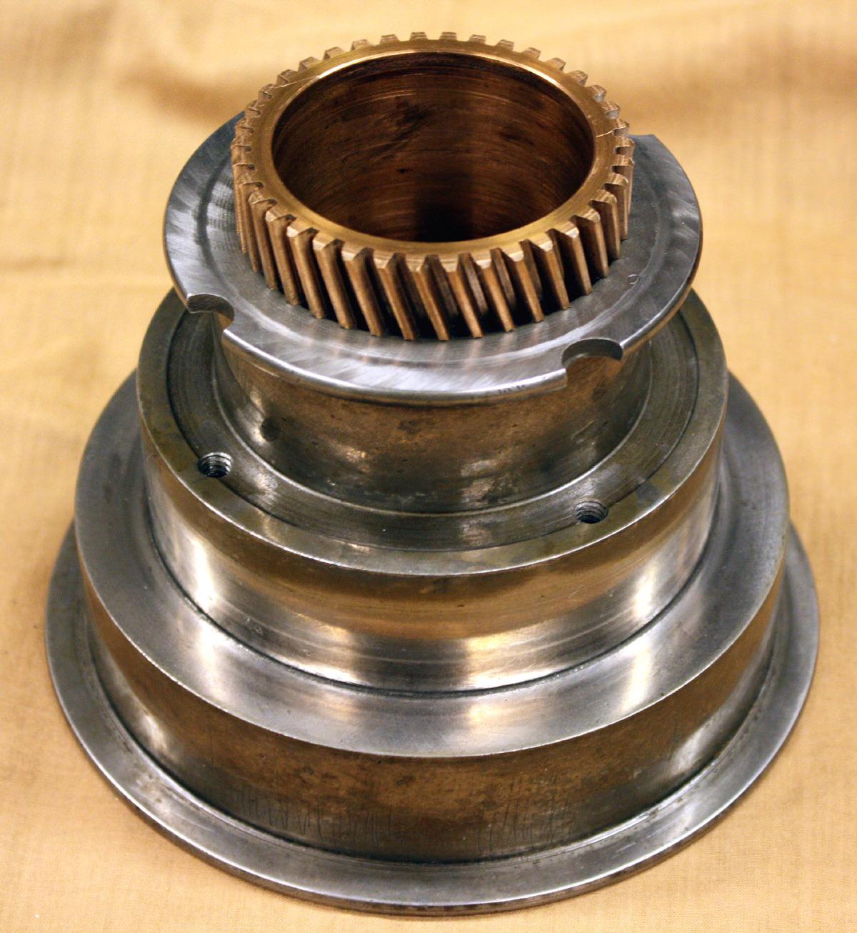
The giant spindle assembled into the headstock casting
|
|
|
|
|
|
|
|
|
|
|
|
|
|
 |
|
|
|
|
|
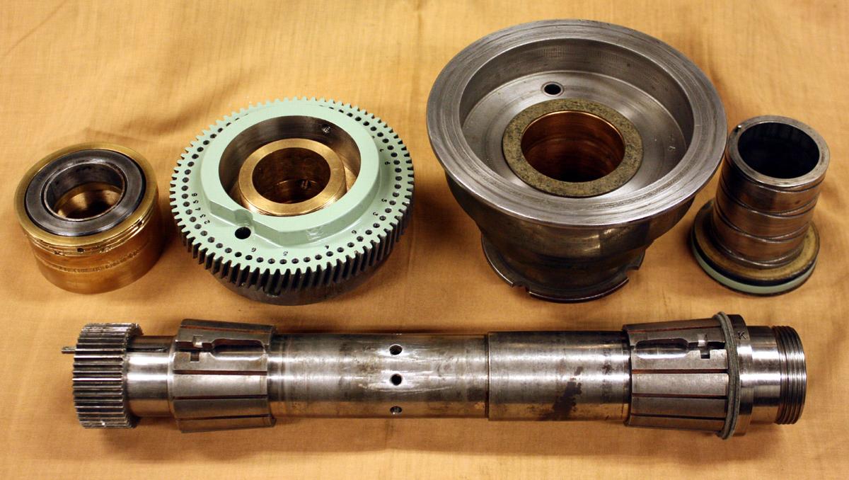
Headstock spindle components - artistry in metal
|
|
|
|
|
|
|
|
 |
|
|
|
|
|
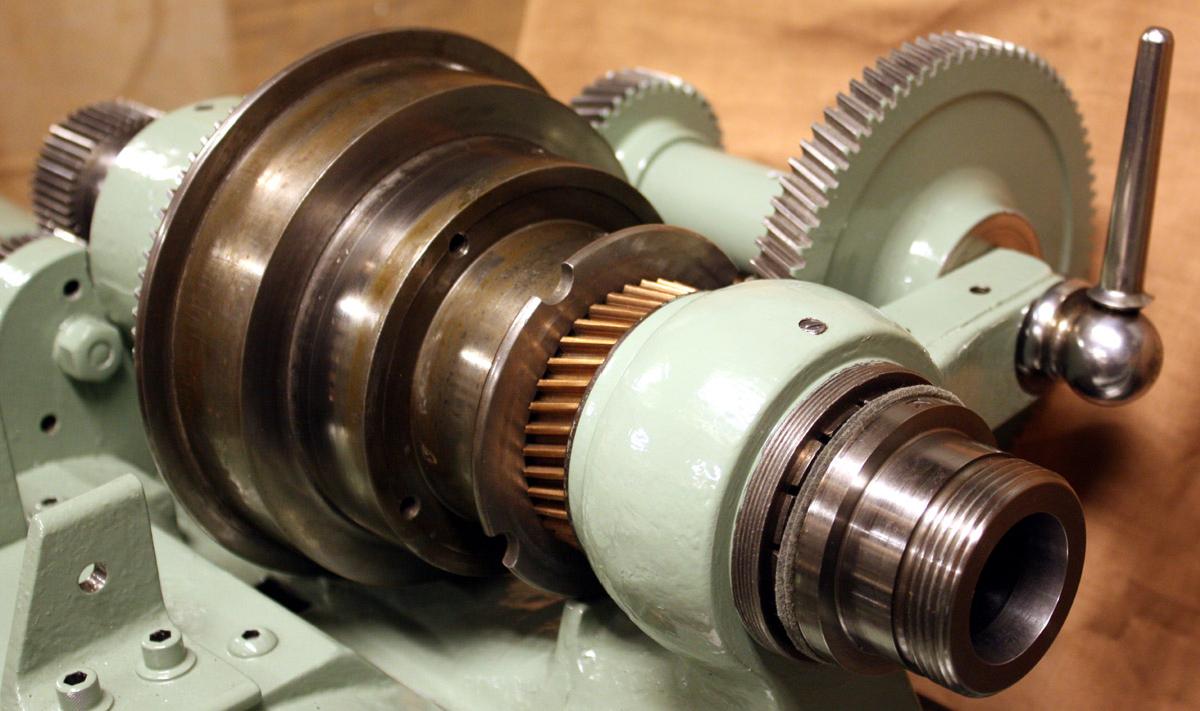
Assembled headstock spindle, pulley, backgears bearings and changewheel drive gear
|
|
|
|
|
|
|
|
 |
|
|
|
|
|
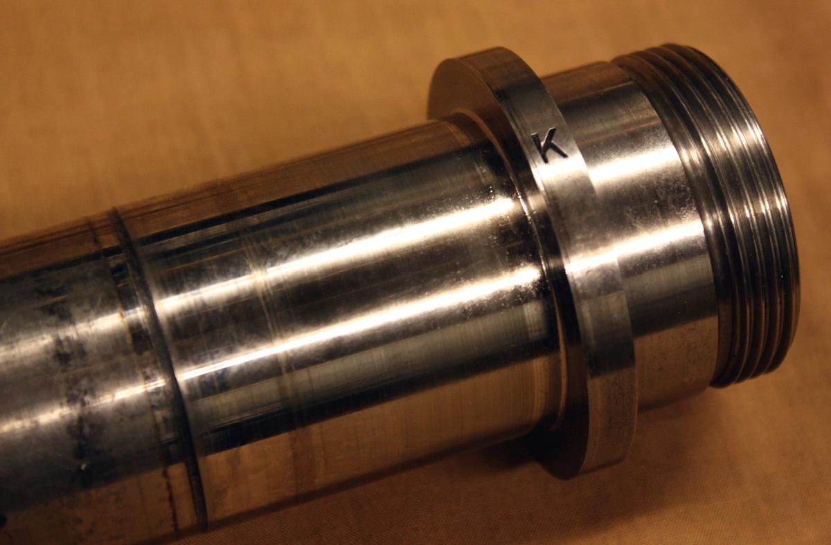
Even after decades of use the hardened spindle shows only minimal sings of wear
|
|
|
|
|
|
|
|
 |
|
|
|
|
|
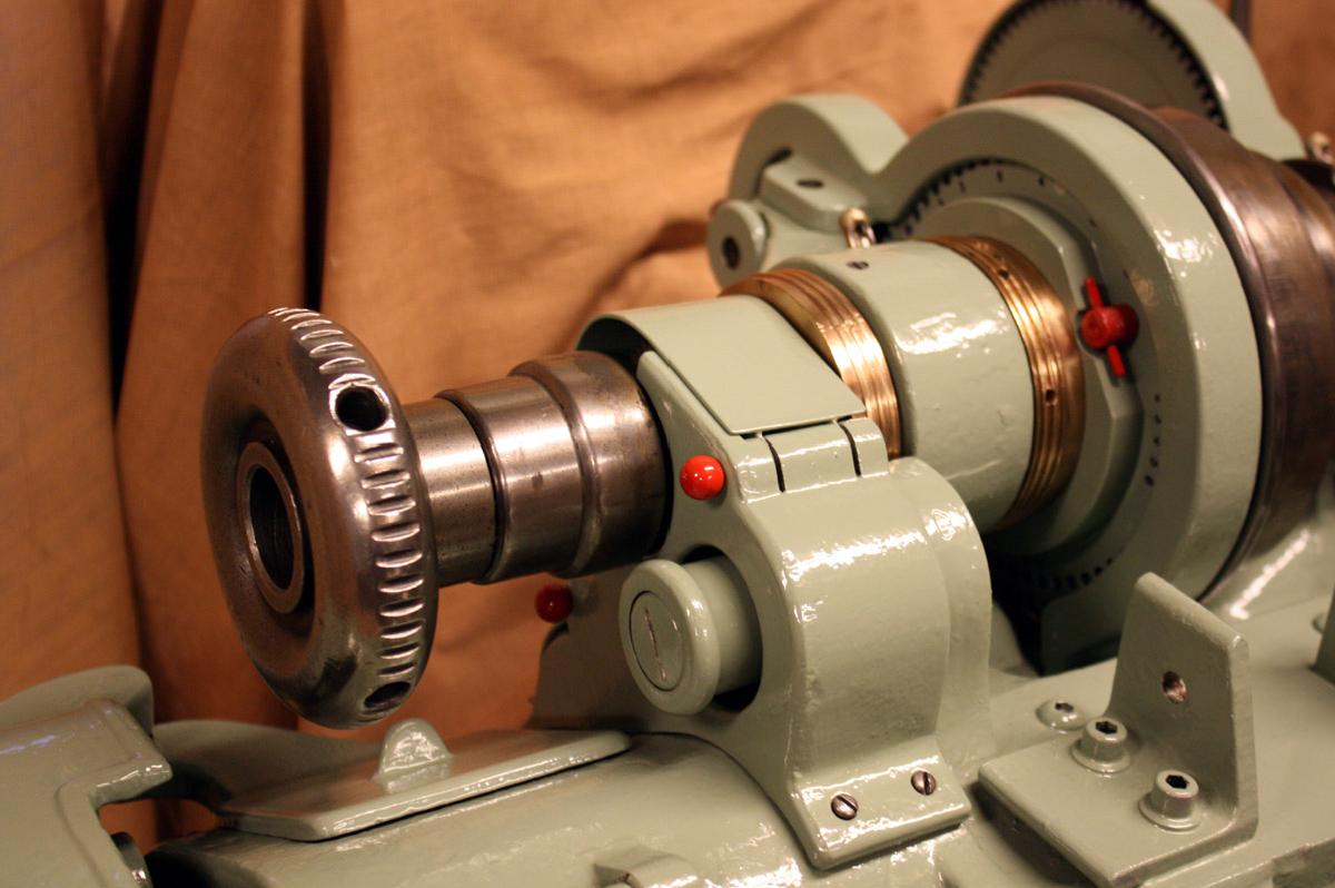
Spindle end with collet drawbar and covers for the backgears and drive gear in place
|
|
|
|
|
|
|
|
|
|
|
|
|
|
 |
|
|
|
|
|
|
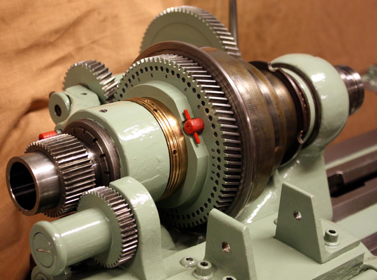
Covers removed. Like many high-quality lathes, the cataract had the smallest pulley towards the tailstock end of the bed so allowing the bearing to be surrounded by the maximum amount of metal. The red pin disengages the spindle bull wheel from the pulley to allow the engagement of the backgears
|
|
|
|
|
|
|
|
 |
|
|
|
|
|
|
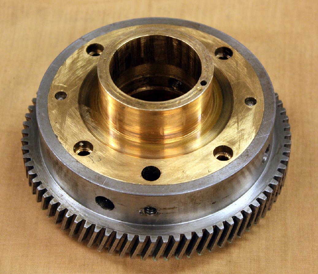
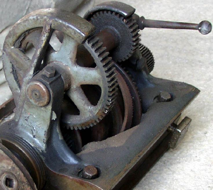
The backgears on this rebuilt lathe have been changed to a helical form for smooth, strong drive. The smaller spindle gear is in bronze and pressed into the pulley (just like a Series 7 Myford) to form a bearing surface for the pulley to turn on when slow speeds are engaged
|
|
|
|
|
|
|
|
 |
|
|
|
|
|
 |
|
|
|
|
|
|
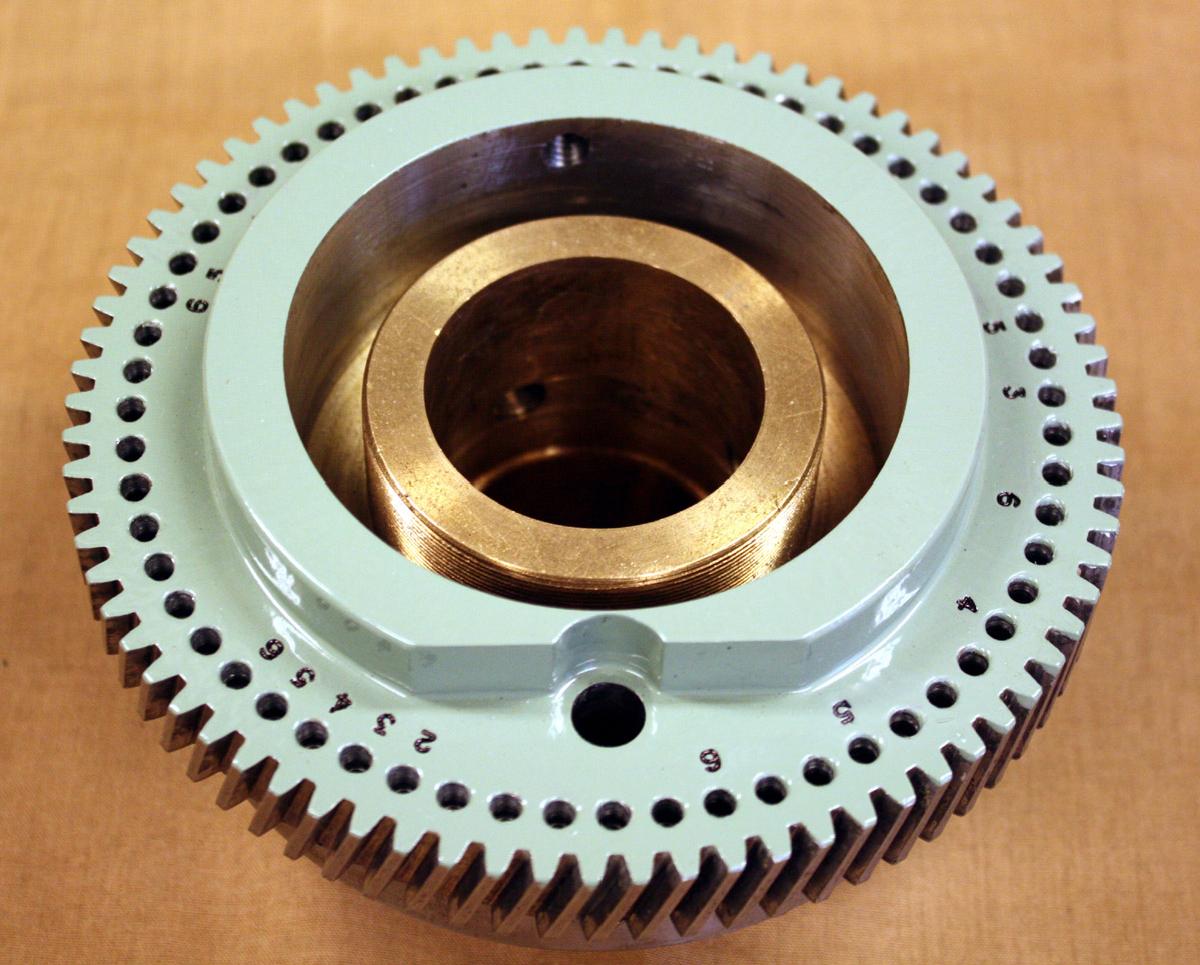
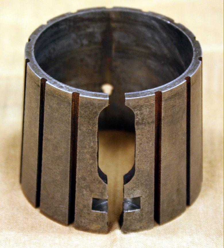
Outside face of the spindle bullwheel and its circle of 60 indexing holes
|
|
|
|
|
|
|
|
|
|
|
|
|
|
 |
|
|
|
|
|
|
Inside face of the spindle bullwheel and its bronze insert
|
|
|
|
|
|
|
|
 |
|
|
|
|
|
|
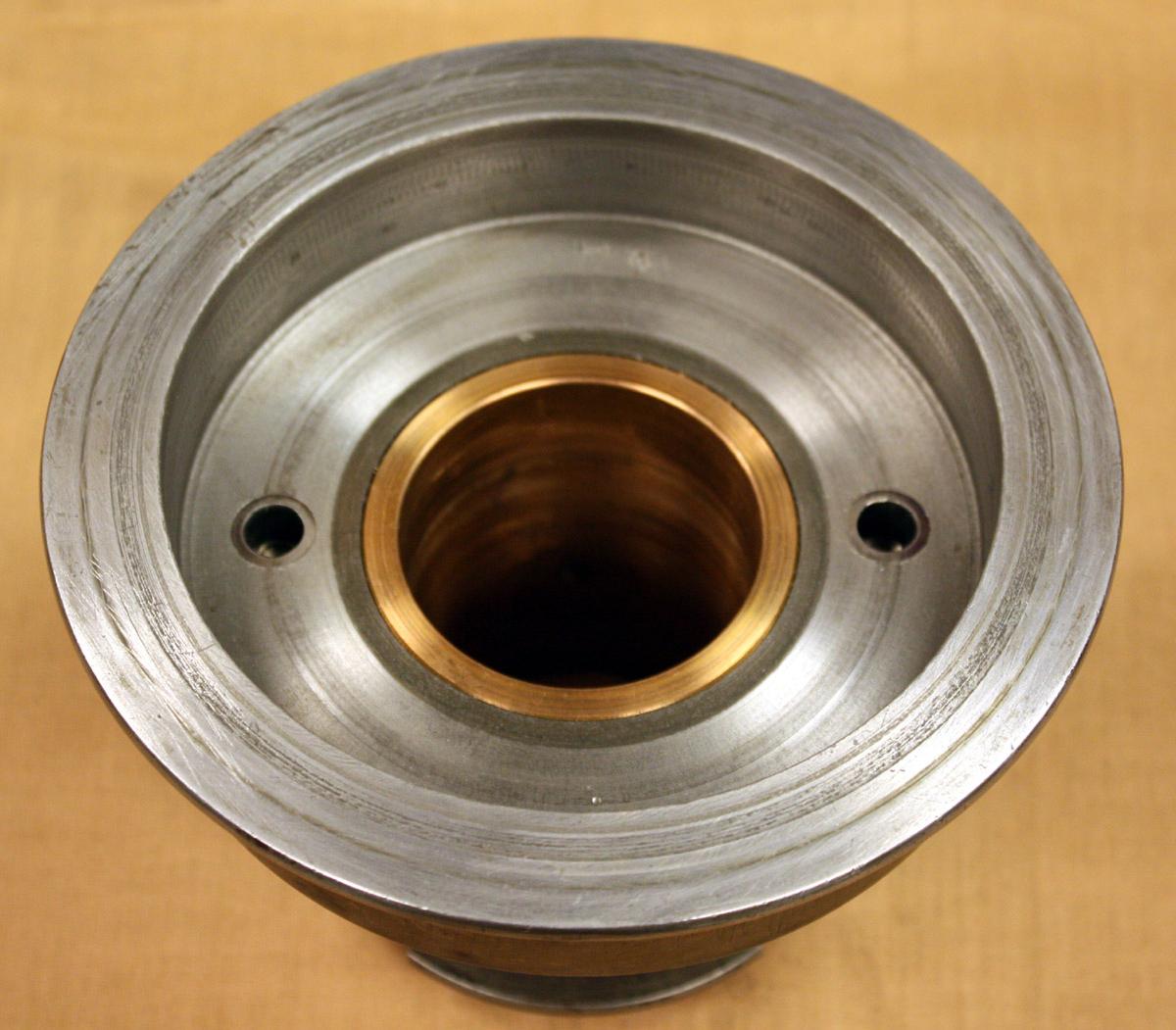
Beautifully-made, long-life spindle bearing
|
|
|
|
|
|
|
|
 |
|
|
|
|
|
|
An unrestored headstock showing the original backgears and their engagement lever
|
|
|
|
|
|
|
|
 |
|
|
|
|
|
|
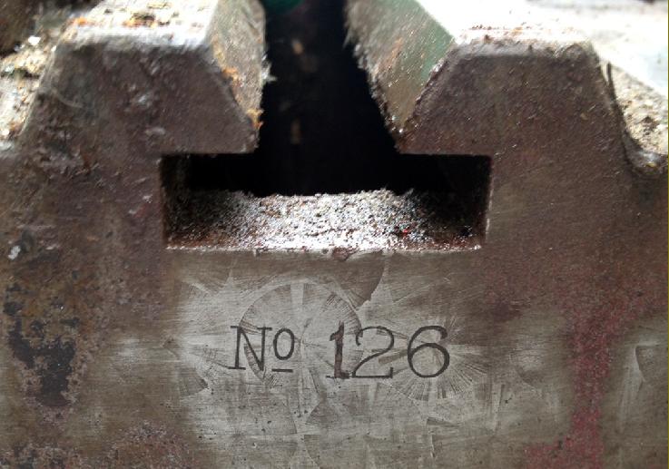
No. 126 - discovered in Birmingham during 2013
|
|
|
|
|
|
|
|
|
|
|
|
|
|
 |
|
|
|
|
|
|
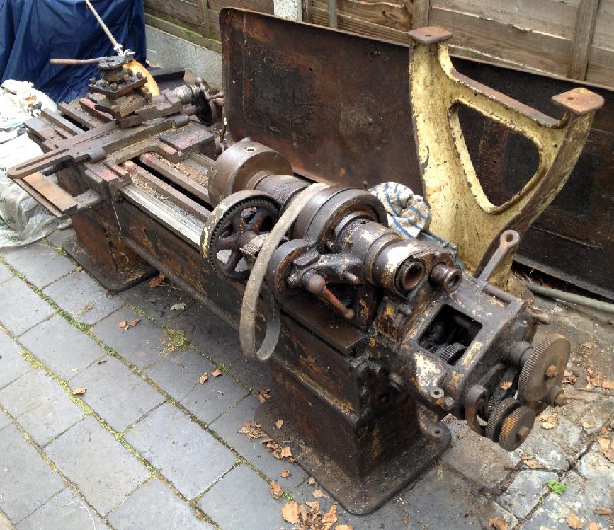
Complete and ready for restoration
|
|
|
|
|
|
|
|
 |
|
|
|
|
|
|
Note, on this example, the very large diameter micrometer dial on the cross-feed screw
|
|
|
|
|
|
|
|
 |
|
|
|
|
|
|
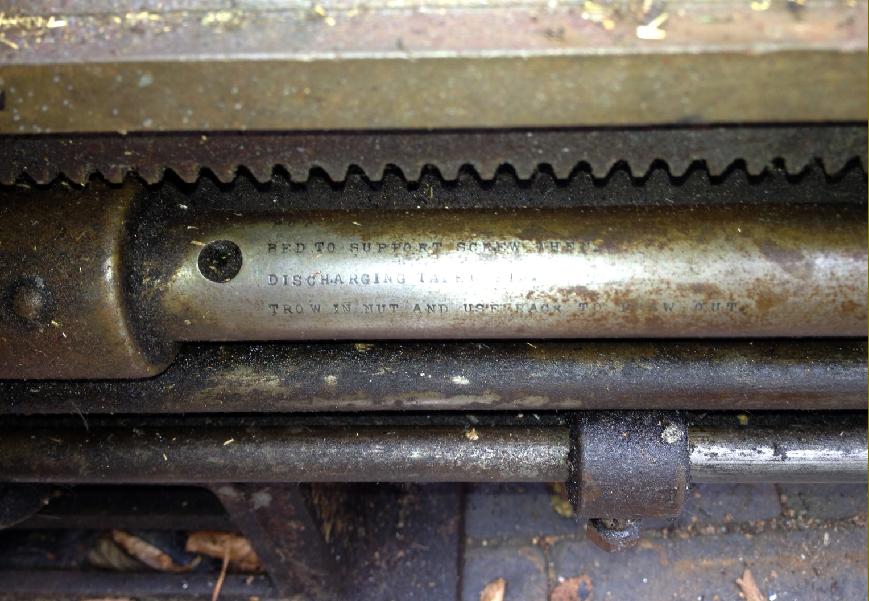
Special screwcutting instructions engraved on the leadscrew
|
|
|
|
|
|
|
|
|
|