|
Home Machine Tool Archive Machine-tools for Sale & Wanted Books Accessories Cataract Accessories Cataract Stands & Drives Cataract Drills & Pinion Cutter "Quick-change" Toolroom Lathe Cataract Millers Hardinge History Cataract Home Page Hardinge Elgin Lathes & Millers |
A photograph taken in the centre of the author's home town of Sheffield, England, at the end of the 19th century shows that the largest advertising hording in this industrial metropolis was taken not by a maker of machine tools, cutlery or steel - but by a manufacturer of industrial drive systems. In factories of the time the vast majority of machines did not have their own drive motor, but were connected to a centrally-driven transmission system that snaked around the roof of the factory using up vast quantities of hangers, bearings, brackets and associated ironmongery before finally arriving at what was often a complex, multi-speed countershaft system directly over the machine itself. It is hardly surprising that the makers of such equipment probably made more profit than the machine companies themselves. Thus, one of the most intractable difficulties faced by designers of all early machine tools, especially small ones, was that of providing a compact, efficient, slip-free, reliable and easily-used transmission system. Cataract themselves admitted that this aim had infrequently been met and so, to counter the suggestion that Precision Bench Lathes were mere toys unable to be employed productively in industry, they designed a set of stands and drive systems to overcome as many of the problems as possible - although this was always at a huge additional cost. The solution, in order to generate both a suitable speed range and arrange for the machines to be stopped, started and reversed quickly, was to combine stands and drive systems in one unit and operate the controls through foot pedals and hand levers connected to wire-operated belt shifters and clutches.
All early Cataract stands were of a similar design and based on threaded, cast-iron feet into which fitted 1.25-inch diameter gas pipe. The tops of the stands were made from clear pine lumber, sometimes covered with a 20-gauge thick sheet of steel which was galvanised and provided with a beaded and turned edge. The whole structure was bolted to both to the floor and often the ceiling as well (to a maximum recommended height of eleven feet) and braced by 1/2" guy rods, threaded left and right-hand for ease of adjustment. As an alternative, the stands could be provided as rather more rigid "free-standing" units with an additional system of pulleys mounted underneath and the overhead countershafts and electric motor carried on shorter acorn-topped posts braced by horizontal tie rods. Cataract provided not only complete stand and drive units but also all the small parts necessary for a customer to built their own.
Later Cataract and Hardinge drive systems were simplified by redesigning the lathes to accept the drive from underneath. Unfortunately, while this resulted in a neater, safer and less-expensive assembly, it meant that the lathes could no longer be set up on the owner's own bench. The final solution to the problem of neatly integrating a lathe and its drive system came in 1932 with the introduction of the American-made Atlas 9-inch model..


|
Shown with a Cataract No. 3 Lathe mounted, this was the basic stand as supplied in the early part of the 20th century. The wooden top was 72" x 28" and the tubular uprights required bracing against the ceiling. A variety of countershafts was available with both extra speeds and a reverse drive engineered into them. |
||
|
The same stand as shown above could also be arranged to drive an end-of-bed-mounted horizontal milling machine. |
||

|
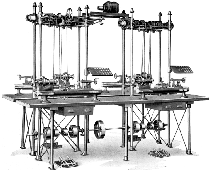
Cataract Two-Lathe Outfit on the standard R-2 bench with a clear pine wooded top 96" long and 28" wide. Inset into the top was a section of 20-gauge galvanised iron with a beaded and turned edge. The feet were of cast-iron threaded for 1.25" gas pie. The assembly was braced both ways with 1/2" guy rods, threaded left and right for ease of adjustment. |

|
|
||

|
Cataract Standard R-2 Double Bench Unit with Under Drive. |
||

|
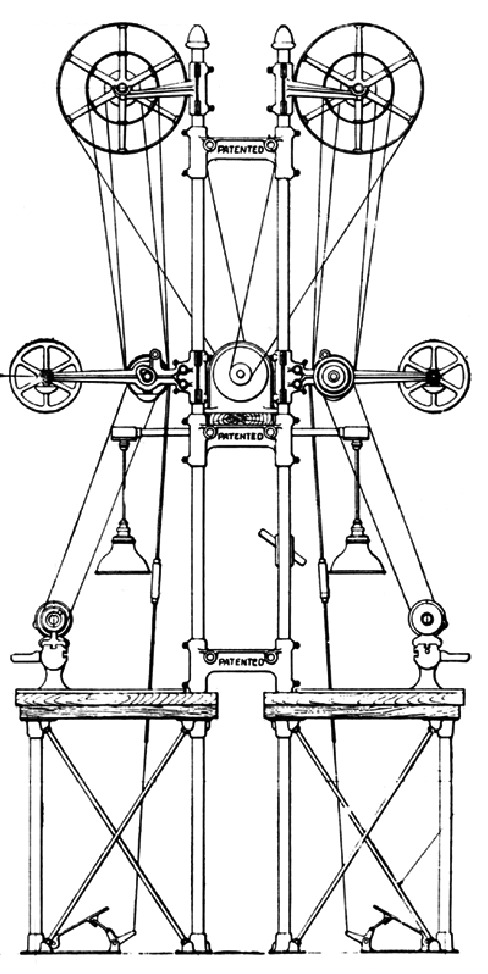
When lathes with standard and high-speed overhead drives (for grinding and milling) precision drills and bench millers were combined in one drive system, the complexity became almost overwhelming with both overhead and underdrive countershafts integrated into one vast array of unguarded, thrashing belts. |
||
|
|
||
|
2-speed jackshaft for wall or ceiling mounting - recommended maximum speed 375 rpm. This unit was designed to drive to the countershaft unit shown immediately below. |
||

|
"Two-Speed Counter" for drive by the jackshaft shown at the top of the page. This unit was of the Fast-and-Loose type with two "free-to-rotate" 6-inch diameter pulleys (each able to take 1.25-inch wide belt) positioned at either side of a central and wider pulley that was keyed to the central shaft. By operating foot or hand-controlled strikers the operator was able to instantly change from one speed to the other. Combined with the 1-inch wide 3-step pulley (that drove down to the machine tool) a total of 6 speeds was available. |
||

|
3-speed jackshaft for wall or ceiling mounting - recommended maximum speed 375 rpm. This unit was employed to drive the complex and very much more expensive 3-speed "Plain" and "Universal" Counters shown below. |
||

|
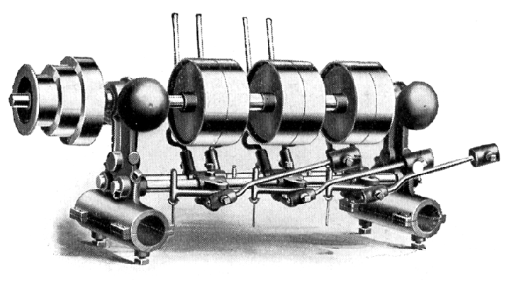
3-speed "Universal" countershaft for use on the stands constructed from gas pipe; the same unit was also available with flat feet for wall or ceiling mounting. The large-diameter, narrow overhead pulley was used to run high-speed grinding and milling heads held in the lathe toolpost. |
||
|
|
||

|
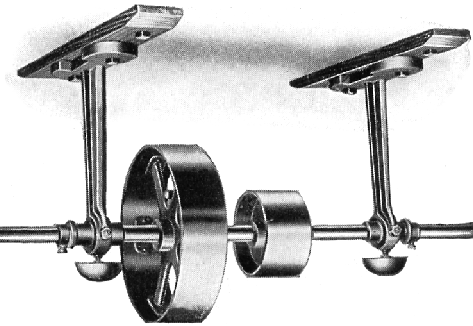
The jackshafts for use on the bench stands were fitted with hangers incorporating clamps to grip the gas tubing framework. Like the units for wall and ceiling mounting they could be lengthened to accommodate multi-machine drives through the use of a longer through shaft and additional supports. |
||

|
Cataract high-speed countershaft for driving grinding and milling cutters |
||
|
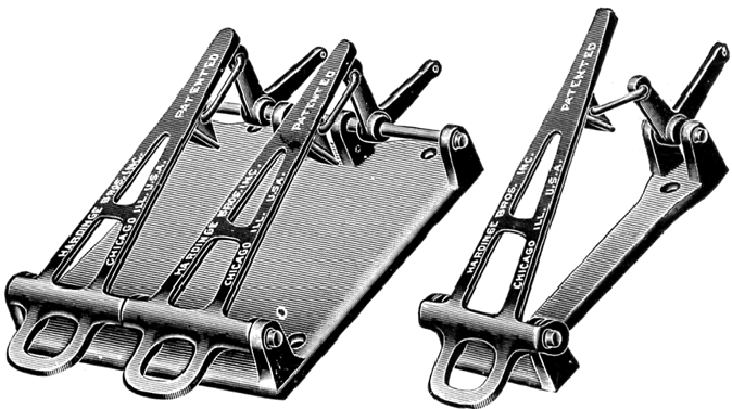
Cataract Automatic Locking Foot Treadles. These devices were available as a single units (Part No. 185) as a double (part No. 186) or as a triple (Part No. 187). There were intended to operate belt shifters on fast-and-loose countershafts with a downward motion on the treadle engaging and locking the drive and a light tap on the heel part moving the belt back onto the loose pulley and so stopping the machine. |
||
|
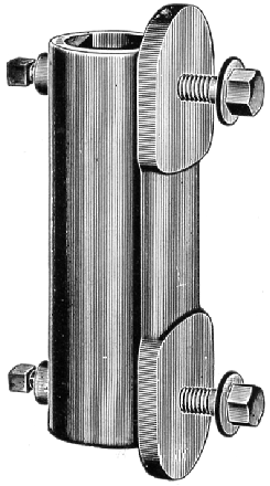
Cataract supplied all the small parts necessary to set up a countershaft system: illustrated left is the bracket for holding the 1.25-inch diameter gas piping against a wall or ceiling where a home-built stand was being constructed. |
||
|
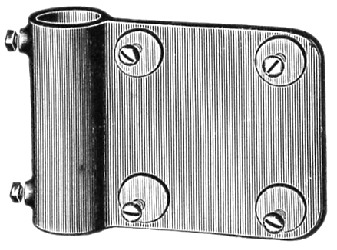
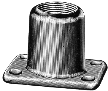
An essential part of the cataract "gas-pipe" stand was the cast-iron sockets into which the pipes screwed. These were supplied in left and right-hand threaded versions with the intention that not only could the whole assembly be levelled up by their use but, by arranging the Jack and Countershafts correctly, belt tension could be easily adjusted as well. |
||
|
"Quick-change" Toolroom Lathe Cataract Millers Hardinge History Cataract Home Page Hardinge Elgin Lathes & Millers & Drive Systems Home Machine Tool Archive Machine-tools Sales & Wants Books Accessories |
||