 |
 |
 |
 |
 |
 |
 |
 |
 |
 |
 |
 |
 |
 |
 |
 |
 |
 |
 |
 |
 |
 |
 |
 |
 |
 |
 |
 |
 |
 |
 |
 |
 |
 |
 |
 |
 |
 |
 |
 |
 |
 |
 |
 |
 |
 |
 |
 |
 |
 |
|
|
|
|
|
|
|
|
|
|
|
|
|
|
|
|
|
|
|
|
|
|
|
|
|
|
|
|
|
|
|
|
|
|
|
|
|
|
|
|
|
|
|
|
|
|
|
|
|
|
|
|
|
|
|
|
E-MAIL Tony@lathes.co.uk Home Machine Tool Archive Machine Tools For Sale & Wanted Machine Tool Manuals Machine Tool Catalogues
Hardinge "Cataract" Millers - USA Cataract/Hardinge Millers of the 1930s Cataract Lathes Hardinge Lathes
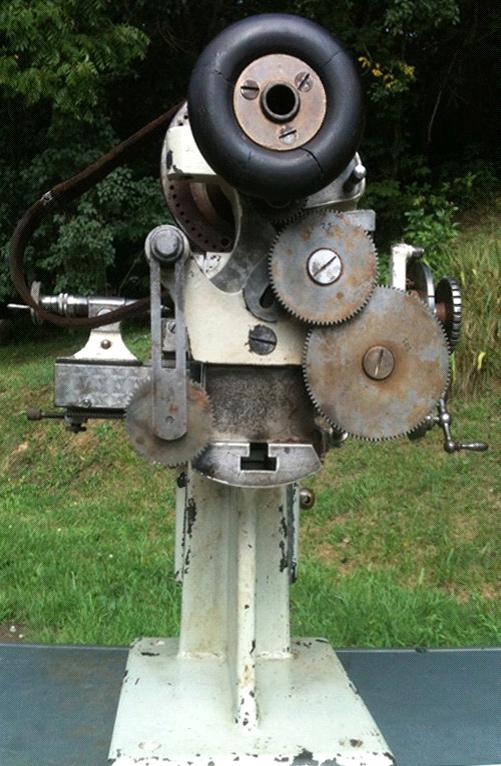
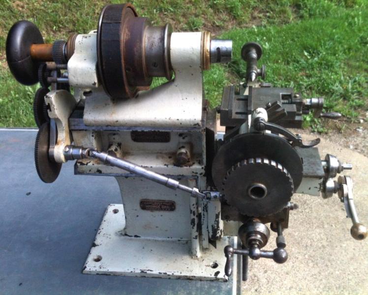
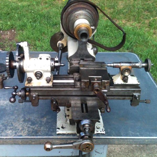
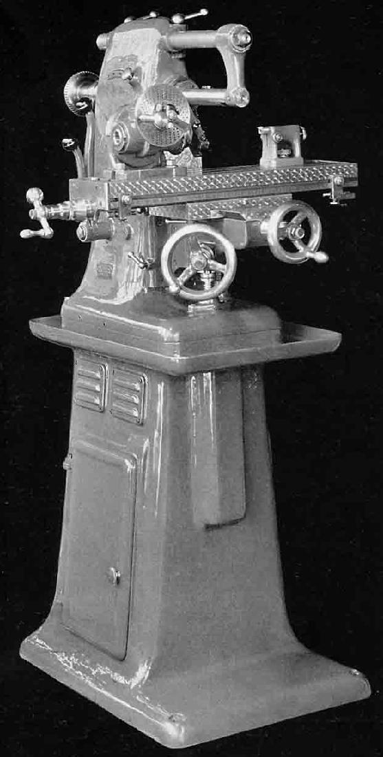
Manufactured by the American Hardinge precision lathe and collet company the first Cataract horizontal and vertical millers, constructed before World War 1, were small machines standing just 161/2" high. They made use of several already-existing parts - the main body casting was topped with a replica of the precision bench-lathe bed, to which a slightly modified No. 3 lathe headstock was bolted, whilst the knee and compound table were identical to those offered as conversion kits to turn the company's lathes into horizontal millers. As a further economy the table power-feed arrangement was provided by the same drive used on the lathes as a screwcutting attachment - and also retained the very useful adjustable automatic knock off control. There was no overarm support for the cutter and the machine would have been limited to work of a lighter duty only. The knee and compound table of the vertical miller were identical to those used for the horizontal and, whilst the head casting was completely different, it also used the same spindle and bearings found in the Cataract No. 3 lathe headstock. With a maximum clearance of 61/2" from the spindle, the table was 12" long by 33/16" wide; it carried one central T slot, which had bevelled sides to locate fittings such as the dividing unit, and two plain outer T slots for clamping work. The table had a cross travel of 4" and could be moved longitudinally through 51/2" by a screw feed or by 5" using a rack-operated lever mechanism that bolted to the same location used for the power-feed attachment. Before the lever feed could be engaged, the main slide nut had to be removed but, as this was exposed on the side of the knee casting, the job took only a moment. All of the indexing type, the micrometer dials were 17/16" in diameter and graduated to read in thousandths of an inch. Another much larger and stronger miller, the No. 5, was also produced from around 1912 and continued to be manufactured, in a modified form with neat, enclosed drive systems and 2-speed motors, into the 1930s and 1940s. Improved Cataract millers, first produced during the 1930s, followed to some extent the development of the company's bench lathes - having completely enclosed V-belt drive systems with the two-speed motors operated by neat external levers. Later still, Hardinge dropped the Cataract label and advertised the machines, with further modifications and additions to the range, under their own name. All Hardinge Cataract millers were available with a range of high-quality accessories, some of which are shown lower down this page. Continued below:
|
|
|
|
|
|
|
|
 |
|
|
|
|
|
|
The original Cataract bench-lathe miller conversion the knee and table assembly of which were used on the company's first self-contained horizontal and vertical millers.
|
|
|
|
|
|
|
|
 |
|
|
|
|
|
|
Above and immediately below: the original pre World War 1 horizontal and vertical millers that made use of the knee and table used to convert the company's precision bench lathes into simple horizontal millers.
|
|
|
|
|
|
|
|
|
|
|
 |
|
|
|
|
|
|
Whilst the head casting of the vertical miller was completely different, it used the same spindle and bearings of the No. 3 lathe headstock.
|
|
|
|
|
|
|
|
|
|
 |
|
|
|
 |
|
|
|
|
|
|
|
The heavier of the two Plain Dividing Heads had a 6" diameter indexing plate, a "half-automatic" indexing mechanism, adjustable bearings and a hardened and ground spindle with a taper to accept either No. 3 or No. 4 Hardinge collets. A sixty-notch indexing plate was supplied as standard but plates could be obtained with any number of notches up to and including three hundred and sixty six.
|
|
|
|
|
|
|
|
|
|
|
The standard 21/8" centre height Plain Dividing Head had a 4" diameter indexing plate and a spindle to accept Hardinge No. 3 collets.
|
|
|
|
|
|
|
|
|
|
|
|
|
|
 |
|
|
|
|
|
|
|
|
The tailstock for the dividing heads had a 11/2"-travel spindle fitted with a Hardinge No. 3 taper. To the end of its production, in the 1930s, it continued to use that hallmark of early precision machine tools - a handwheel with the centre section turned away and two resulting raised rims each delicately knurled.
|
|
|
|
|
|
|
|
|
|
|
|
|
 |
|
|
|
|
|
|
Cataract No. 5 bench horizontal miller (complete with the maker's standard-fit 6" dividing attachment) as first manufactured during the early years of the 20th century. This was a very much more substantial and massive machine than the company's first bench millers with a 24" x 6" (working surface 20" x 6") table that carried three ordinary 7/16" T slots; the longitudinal travel was 12" and the cross and vertical both 6". The spindle, of "crucible steel" - a quality endorsement still popular in the early 1900s - ran in 3 degree taper bearings of phosphor bronze that were adjustable for wear and was fitted with a "Hardinge" 5C collet nose with a maximum capacity of 1 inch. In hardened steel, the overarm was ground and lapped to a perfect fit within the casting; the cutter arbor was 7" long and 7/8" in diameter and the distance between arbor and overarm 4 inches. The largest of the 4-step spindle pulleys was 61/2" in diameter and took a 13/8"-wide belt. For bench mounting the miller's base was 26" deep and 12" wide and the machine weighed, in basic form, 300 lbs. By the 1930s the No. 5 miller had been considerably modified and, in line with the company's bench lathes, had acquired an enclosed headstock and a drive system with a 2-speed electric motor controlled by a pair of concentrically-mounted external levers (see below).
|
|
|
|
|
|
|
|
 |
|
|
|
|
|
|
Hardinge BB4 Appearing to have been advertised with just the Hardinge, as distinct from the Cataract name, were the small BB4, a developed version of the light-duty horizontal MD4 (and available with a pre-loaded ball-bearing spindle only) and a tool-room horizontal miller that could be supplied in either "TM" form as an ordinary universal plain (with an optional vertical head) or as the "UM" when fitted with a swivelling table designed to mount a universal spiral-dividing head for cutting spirals. Like all small Hardinge millers the BB4 was superbly made from top-quality materials and finished to a high standard. Although a relatively small machine, with a table having a working surface just 12" long by 33/16" wide and without an overarm support for its cutters, the hardened and ground pre-loaded ball-bearing 4C collet spindle was driven by 3 V belts - an arrangement that must have provided a more-than-adequate surplus of grip over metal-removing ability. The maximum collet size was 3/4" and the 8 spindle speeds, driven from a 2-speed motor under-slung within the standard sheet-metal cabinet stand, ranged from 180 to 3000 rpm. With hand-scraped ways - and positive locks - the table was almost identical to that fitted to the earlier MD3/MD4 being the same 12 inches long but, at 33/16", just 1/16" narrower. Unfortunately the table travel was slightly reduced on all three axes with a longitudinal movement of 5", traverse of 31/8" and vertical of 5". A generous 24" x 29", the chip tray sat on a stand with a 39" x 38" plan foot - a measurement that included an allowance for the opening of the cabinet's collet and tool-storage doors. By the time this machine became available, the Hardinge habit of supplying an indexing dividing head and tailstock with each miller as standard had stopped and these useful items were confined to the expensive Accessory List. Continued below:
|
|
|
|
|
|
|
|
 |
|
|
|
|
|
Hardinge TM/UM Miller - and copy by Richard Haighton of Burnley, England Made from the mid 1930s until 1977 (an astoundingly long run) the best known and most common of the Hardinge miller range, the TM/UM, was a carefully-designed, heavily-constructed machine intended to be strong and accurate enough for both production and toolroom work. Interestingly, because nothing similar was being built in the United Kingdom, Richard Haighton Ltd. of Canning Street, Burnley (makers of the Haighton Cadet lathe) produced a short run of close copies, probably in either the late 1950s or early 1960s Branded as the Haighton Major HSU1 it is a very rare machine - and few can survive. Fitted with an ordinary table the TM was the standard machine whilst the UM, with a swing table, was the "Universal" model. With a working area of 203/4" x 61/2", the table had a longitudinal travel of 14" (11 =1/2" with power feed) a traverse feed of 51/2" and a vertical movement of 131/4". The optional table power-drive attachment gave rates of travel from 1/8" to 13" per minute and was unusual in providing a total of 32 different feeds. All the gibs strips were of the proper tapered type, giving better support and allowing more precise adjustment. A thoughtful touch was the ability to disengage the transverse handwheel engagement; once released, by sliding a collar towards the micrometer dial, the operator could walk around the machine without fear of nudging the handle and upsetting the position of the table. The double nuts for longitudinal and traverse feed screws were adjustable for backlash and the 3"-diameter micrometer dials were larger than other Hardinge millers with, for the first time, parallel engraved surfaces instead of the bevelled ones used previously. Carrying a 5C collet nose - hardened and ground like all those fitted to Hardinge machine tools - the spindle ran in pre-loaded, grease-packed-for life ball bearings and had 8 speeds from 110 to 1850 rpm. The two speed motor was held on a pivoting plate within the sheet metal cabinet stand and used a 4-step V-belt pulley to transmit power to a 2-step V belt countershaft with the drive then taken vertically upwards, via 2 V belts, to the spindle. Motor-speed switching was controlled by the usual Hardinge method of two concentrically mounted levers, one selecting high and low speeds and stop, the other forward and reverse with a second, separate, stop function. Available as a 7/8" or 1" diameter, the cutter arbor was ground on its end in the form of a 5C collet and held into the spindle by a draw bar equipped with a ball-thrust bearing; it was supported by a drop bracket containing a precision ball race whilst the solid steel 2"-diameter overarm was ground and lapped to be a perfect fit within the main casting. Although not supplied as standard, provision was made to retro-fit a coolant system with all the necessary holes drilled and then sealed with plugs to stop dirt entering. Oil cups were provided to lubricate the longitudinal and traverse feed nuts and the table and carriage slides - in the latter case lines scribed on the table and carriage had to be lined up before oiling to allow the lubricant to reach its correct destination..
|
|
|
|
|
|
|
|
 |
|
|
|
|
|
|
Headstock from the BB4 vertical miller with grease-packed, pre-loaded precision ball bearings and 3 V-belt drive
|
|
|
|
|
|
|
|
|
|
|
 |
|
|
|
|
|
|
Headstock as used on the plain bearing millers with 2 V-belt drive and wick-supplied lubrication
|
|
|
|
|
|
|
|
|
|
|
 |
|
|
|
|
|
|
Right-angle accessory base
|
|
|
|
|
|
|
|
|
|
|
 |
|
|
|
|
|
|
Swivel Base. Designed to allow the indexing head or "Universal Adaptor" (below) to be mounted at an angle on the table and work machined at an angle or taper.
|
|
|
|
|
|
|
|
|
|
|
 |
|
|
|
|
|
|
Universal Adaptor. This device could be fitted either directly to the milling machine table (so that the swivel table was aligned at 90° to the headstock) or mounted on the swivelling base above - so allowing work to be machined at any angle. The 10-inch long T-slotted table could accept any of the usual table-mount accessories including indexing heads and tailstocks.
|
|
|
|
|
|
|
|
|
|
|
 |
|
|
|
|
|
|
Rack-operated table lever feed
|
|
|
|
|
|
|
|
|
|
|
 |
|
|
|
|
|
 |
|