|
Atlas made metal-turning lathes, in various styles, from the early 1930s until the late 1970s but this page deals with the Company first model, the 9-inch, with links above to take you to descriptions and pictures of the later and more common 6-inch, 10-inch and 12-inch models.
Although "V" belts had been widely available from the early years of the 20th century they were in the form of wide and clumsy sectional belts (identical in concept to today's "T-Link" type) and widely used on the final drive of less-expensive motorcycles where their "soft" action took some of the roughness out of the crude power delivery then common. However, in 1930/31 a revolution in transmission design was created when the first continuous-loop, narrow-section "wedge" belt was introduced - with the Atlas company taking immediate advantage of its possibilities by introducing, in 1932, an entirely new lathe, the world's first with an integrated, all-V-belt drive system. With motor and countershaft attached to the back of the machine there was no longer any need for the new owner to find a location in the workshop where he could spend the best part of a day struggling to install a wall or ceiling-mounted countershaft; this machine could be dropped onto a bench, plugged in and used within minutes of arriving home. Described as having a "Compound V-belt Drive" the lathe was of light construction, with a 9-inch swing (4.5-inch centre height) and also appeared in that year's printing of the Sears, Roebuck catalog as the Craftsman "Metalcraft". The machine continued to be sold (and improved in detail) until 1938 when its status had deteriorated to being advertised on the same page - and under the same heading - as the "Utility" 10-inch, the latter a simplified machine based on the much-improved model first offered in 1936.
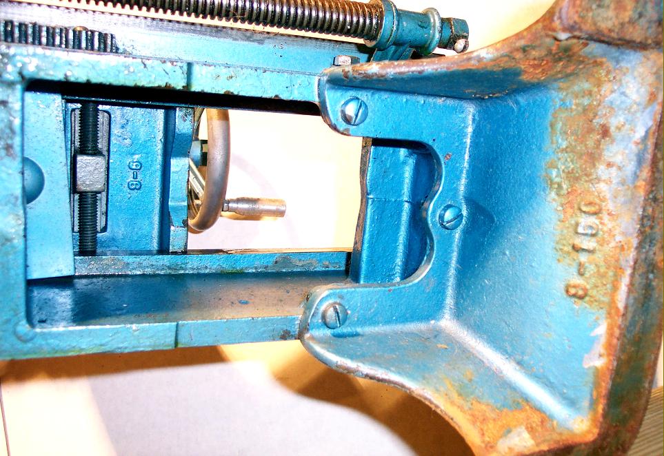
In the first 9-inch catalog the lathe was not accorded a model number but, from the second and subsequent editions, the Type designation 918, 924, 936, 942, 948 and 954 were used with the units and tens digits denoting the bed lengths that gave, respectively 18", 24", 36", 48" and 54" between centres.
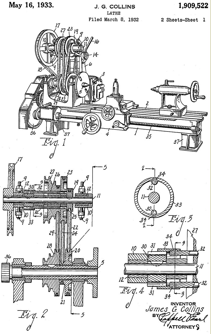
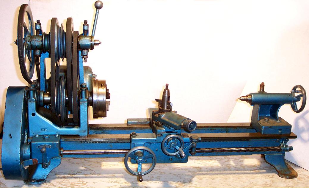
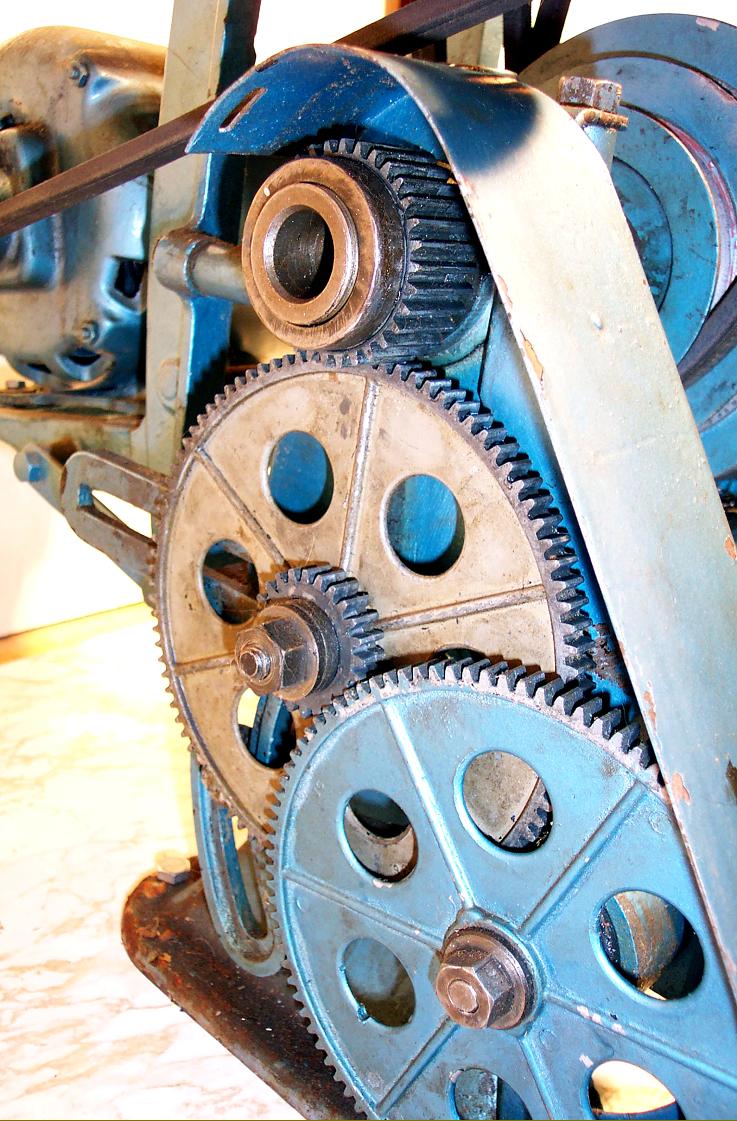
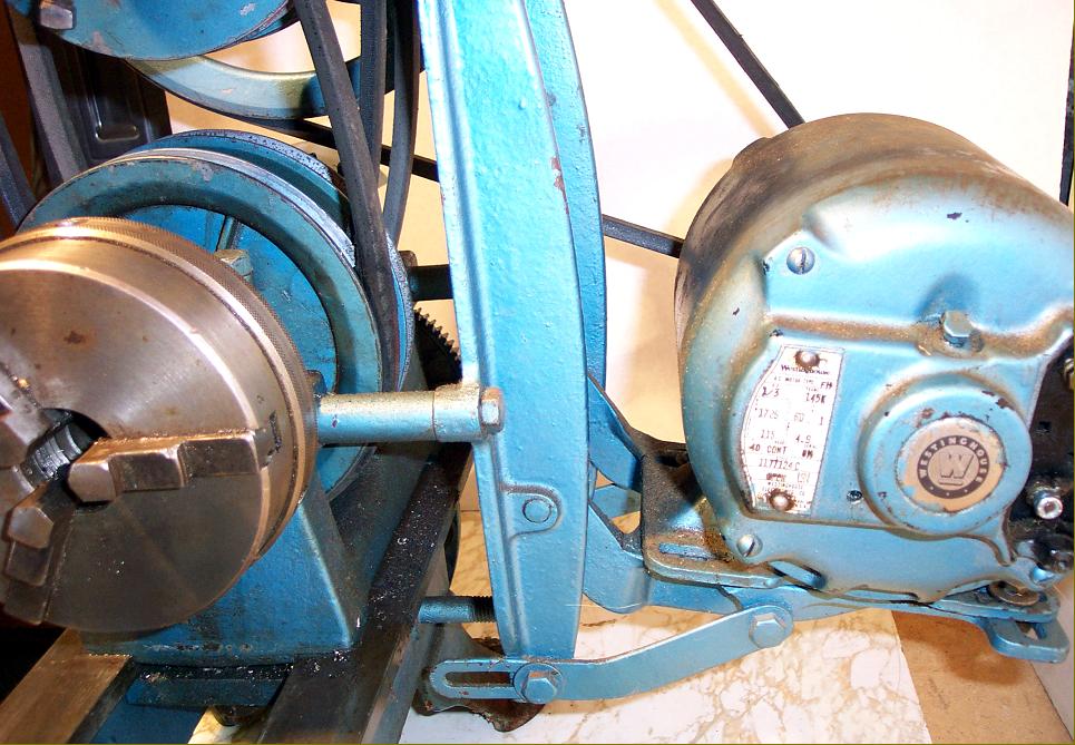
Although a revolutionary machine, everything about the 9-Series minimal appearance would seem to suggest that the management's instruction to the designer was, "Use the smallest amount of metal that allows a component to do its job" - and it is instructive to compare it to the later, more fully-developed, heavier and rigid 10-inch machines shown on other pages. The lathe was not fitted with a backgear (unless specified with a simplified drive as one of the cheaper "Unit Plan" machines) but instead used a "double-reduction" V-belt system running on a Hyatt roller-bearing countershaft unit bolted to the back of the headstock. The lathe's ingenious drive was protected under a United States patent No. 1909522 in the name of James G. Collins - but assigned to the Atlas Press Company, by whom, presumably, he was employed. The application was filed on March 8th, 1932 and granted on the May 16th, 1933.
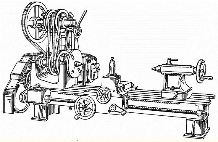
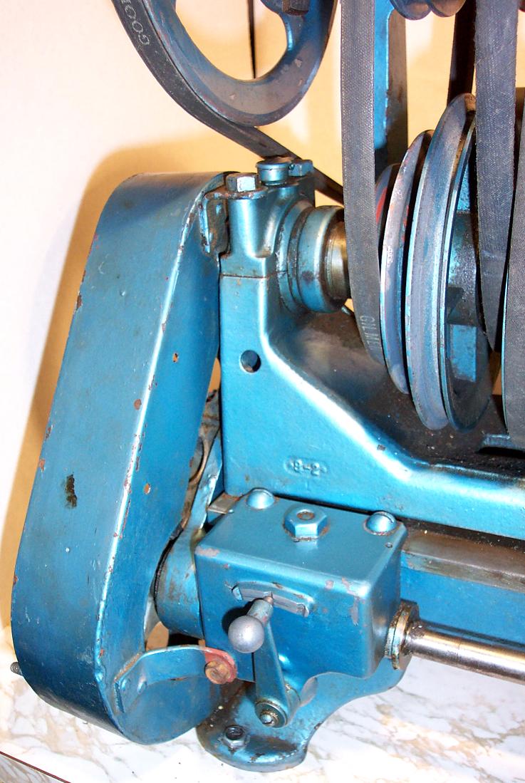
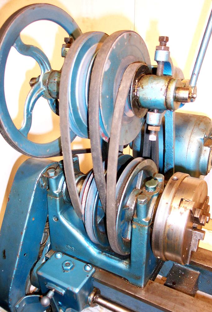
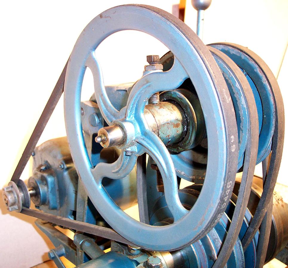
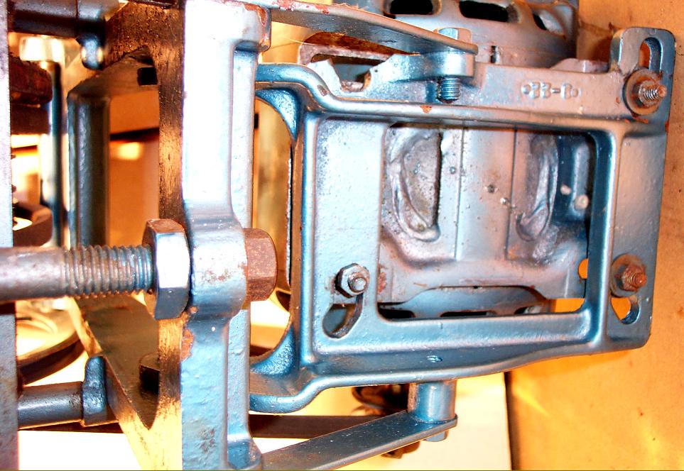
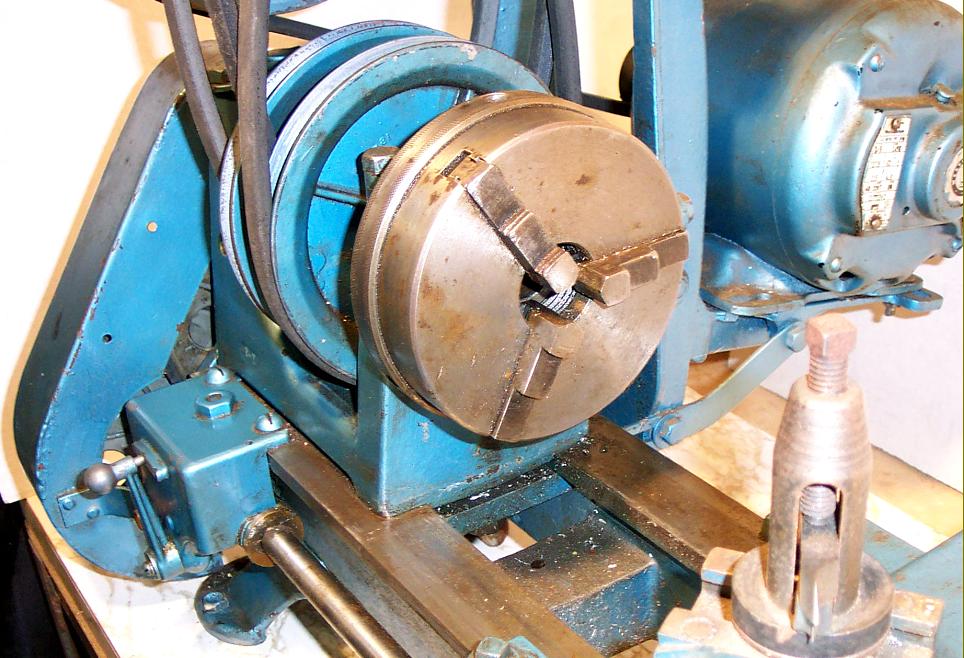
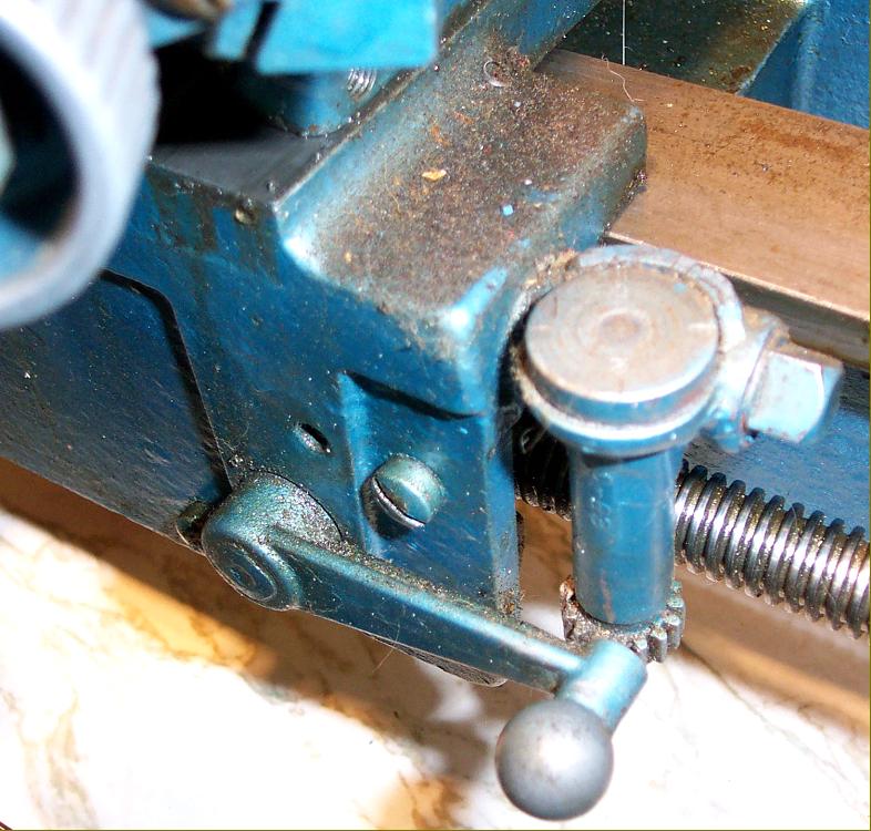
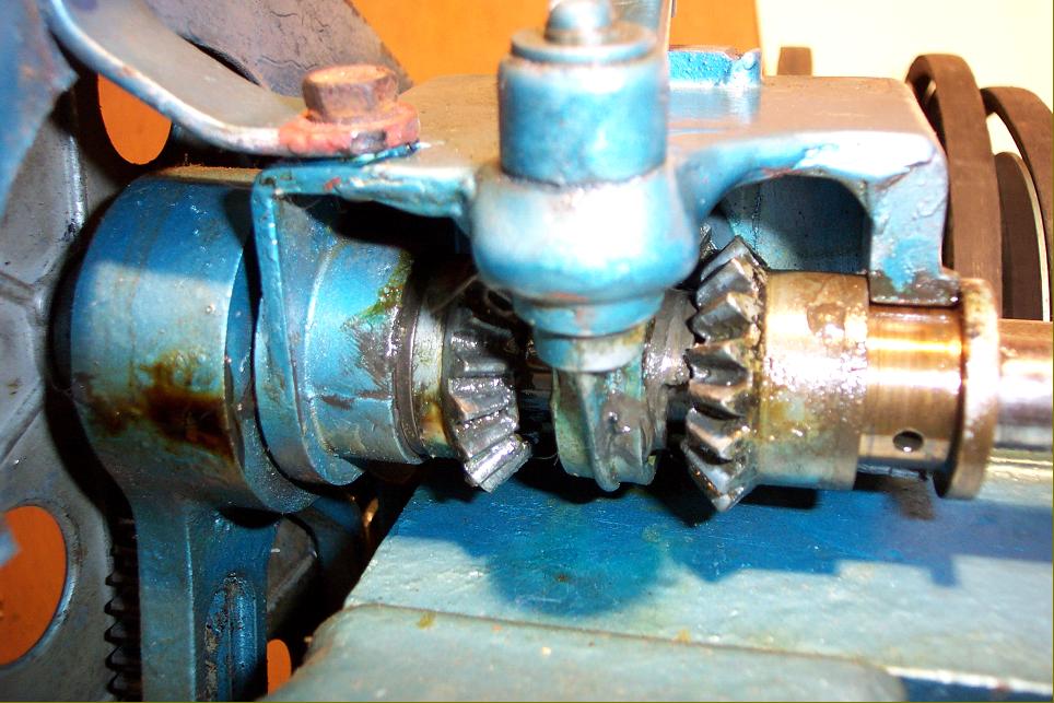
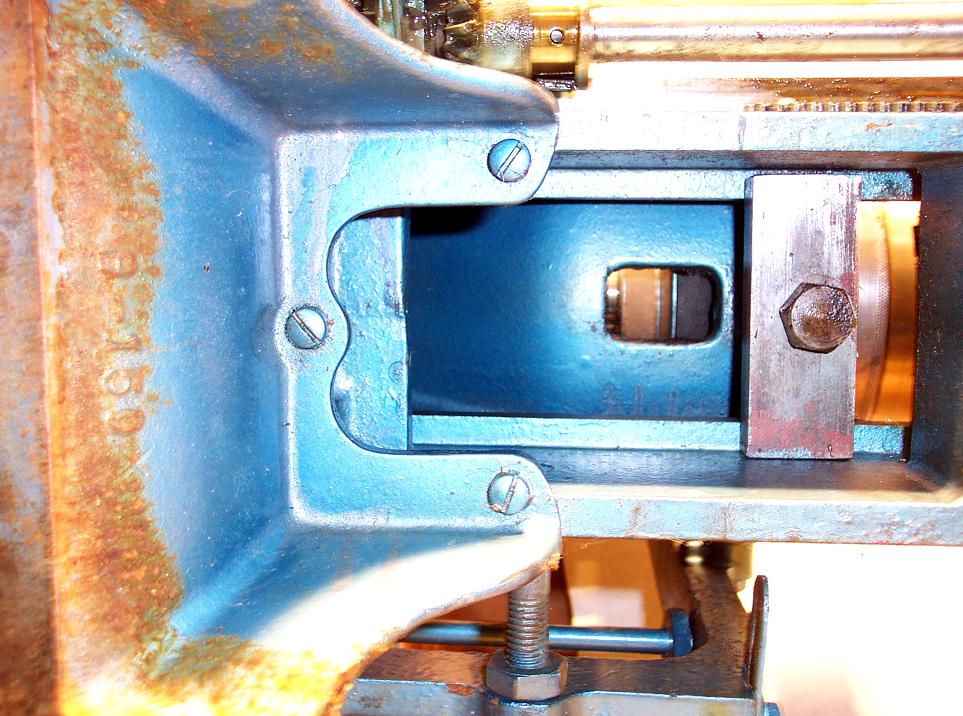
In the "high-speed" position the new drive system was entirely conventional; a small pulley on the motor drove a large pulley on the swing-head of the countershaft from which three direct-drive speeds, of 220, 370 and 600 rpm, were transmitted to a matching 3-step pulley on the headstock spindle. To obtain the low-speed range takes rather longer to explain than to set-up in practice. The countershaft-pulley shaft was formed in two concentric parts, the right-hand side carrying a large, single pulley that was driven separately from the headstock 3-step pulley by a small pulley fastened to its right-hand face. Normally the small right-hand countershaft pulley just idled, but a "shift collar", inboard of the left-hand countershaft bearing, could be moved to the right to bring it into action. When moved, the collar unlocked itself from the shaft and two pins, which extended from its face, went completely through the 3-step pulley and entered the single pulley on its right-hand side - and so locked the two together as a "floating unit". The eventual outcome of these various manipulations was that the drive went from motor to countershaft, countershaft to headstock, back from headstock to countershaft and then, using the 3-speed pulley, back to the headstock to give three slow speeds of 47, 80 and 130 rpm. Although the maker's instructions do not mention the point, some method of releasing the 3-step spindle pulley must also have been provided, otherwise it could not have acted as a drive transmitter. Scrutiny of the picture below should instantly make this interesting down-up-down 'modus-operandi' a little clearer. If you have one of these lathes, but no headstock-spindle drive belts, a good starting point is to try 30-inch "A" section belts (1/2" wide across the top) on the two right-hand pulleys and a 31-inch on the left. The drive, although it eliminated costly backgears, cannot have been a success for, with a drive using only belts, it's difficult to get a really low gear ratio - and the slower the belts run the greater their tendency to slip. In addition it was, (and still is) surprisingly difficult to machine sets of pulleys - and purchase quantities of accurately-sized V belts - so that a multi-step drive works without the need for some small adjustment in tension when the belt is moved from one speed to another. A further problems comes with extended use for, as the pulleys wear, the difficulty of setting the belts "just so" increases. On the Atlas, some differences in belt length could be partially compensated for by adjusting the setting of the countershaft bearings in their simple but ingenious "floating" housings with, of course, the whole head further adjustable for belt tension against an over-centre locking bar.
Because the Atlas was (for so light a machine) capable holding rather large pieces of metal, the original low-speeds-through-belts design was almost certainly dropped because, in "low-gear", if the cutting tool was applied to the edge of a 10" diameter piece of steel, the drive would have been hard pushed to cope. A conventional backgear system was introduced on the later 10-inch lathes - and the problem solved.
Continued below:
|
|