|
Home Machine Tool Archive Machine-tools for Sale & Wanted Books Accessories G. BOLEY LATHE STANDS & DRIVES Boley Capstan Lathes Late Model 4L Boley Milling Machines Stands & Drives 4BK Watchmakers' Lathes 1a, 2a, etc Watchmakers' Lathes Headstock Bearings Triangular Bed Lathe Bevelled-edge Bed Lathe Model 5LZ Production Lathe Size 2 BE2 Precision Drill - an especially fine example being the superb 86-page Lathe & Watchmakers' Tools Catalogue |
|
|
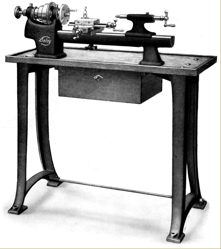
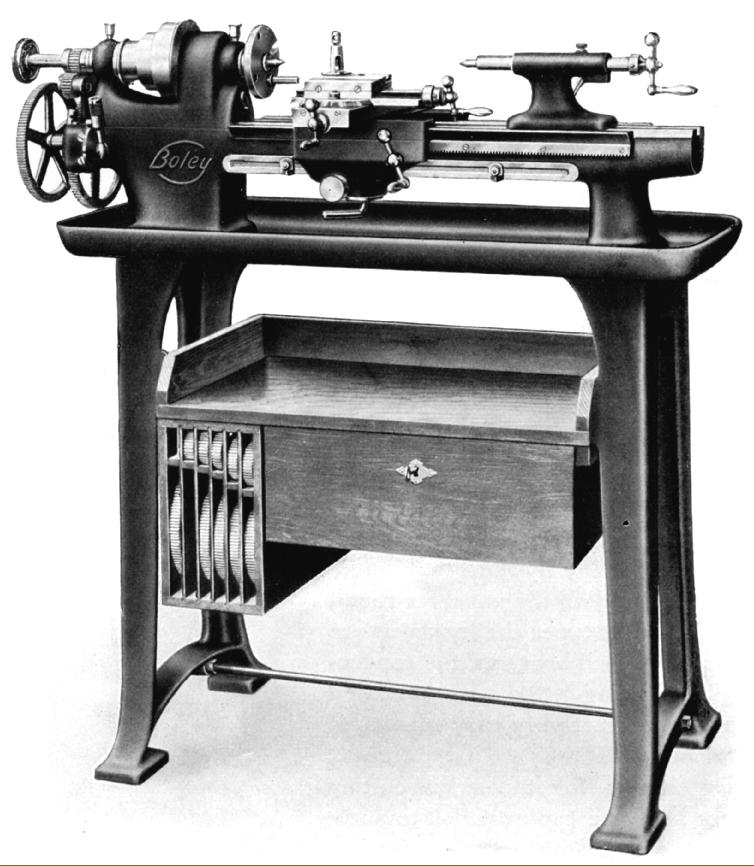
Boley Stand g6 with a 3C lathe. The cast-iron legs were formed with extensions at the top to reach under and support the seasoned oak top. The tool drawer was included in the price. |
|
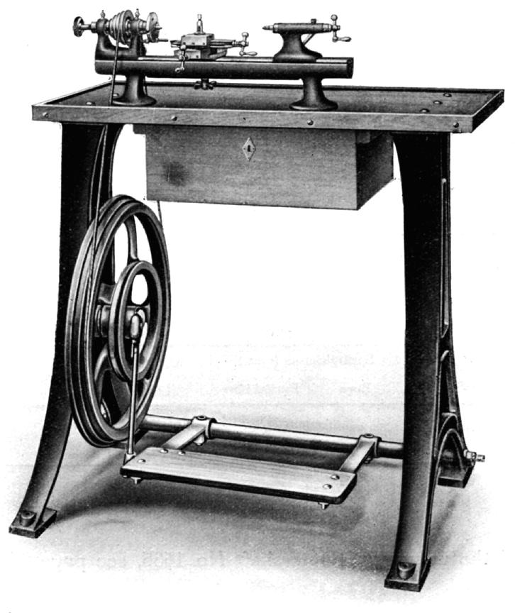
Boley stand g9 with a No. 2B lathe. This lighter precision lathe was driven by a round leather rope from a flywheel running on ball bearing |
|
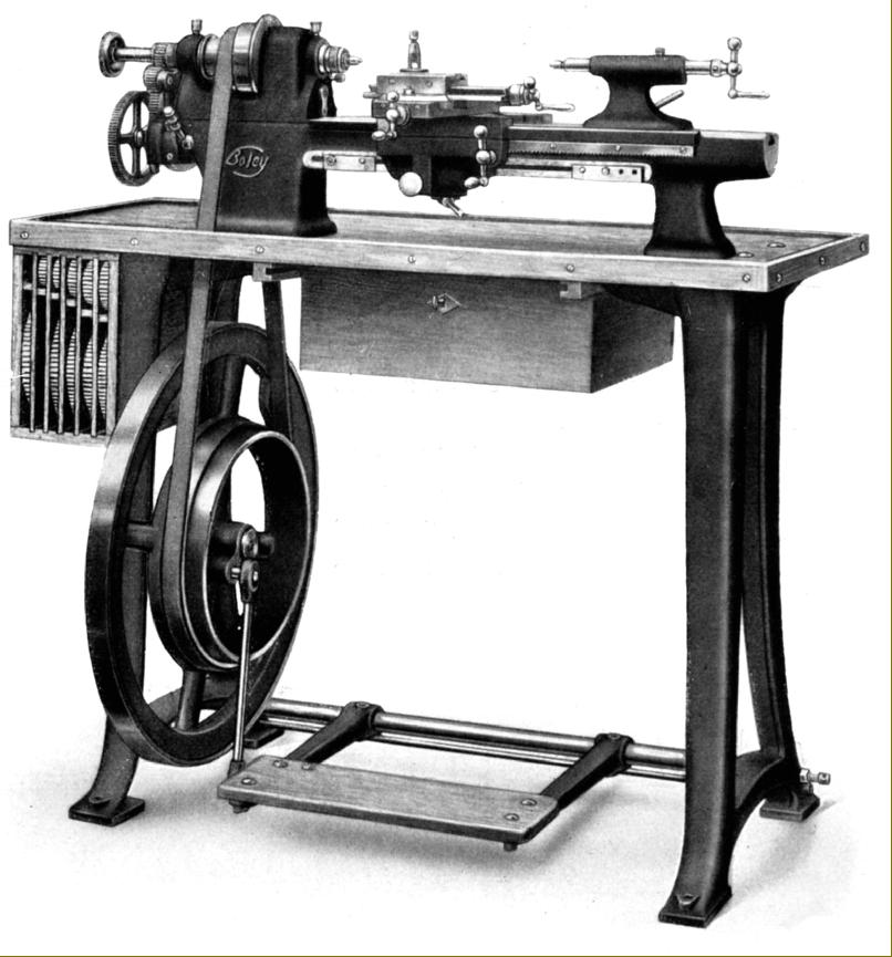
Boley stand g11 with a backgeared and screwcutting 3L lathe. The flywheel was mounted on ball bearings and the connecting rods had hardened, easily turned and long-lasting bearings. A very similar but lighter stand, the g6 ,was made to carry the much smaller No. 2 plain lathe with round-rope drive. The g6 could also, advised the makers, be employed to carry the No. 3 plain lathe. |
|
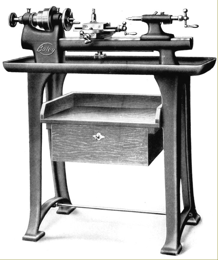
Boley stand g12 with cast-iron chip tray and 3C lathe. The tray had accurately machined faces to mount the lathe and the storage cupboard was topped by a shelf designed to carry a small coolant tank and pump unit. |
|
Boley stand g14 with cast-iron chip tray for screwcutting lathes. Similar to the G12 stand this was even more heavily constructed and the ideal base for the enormously heavy 3L lathe |
|
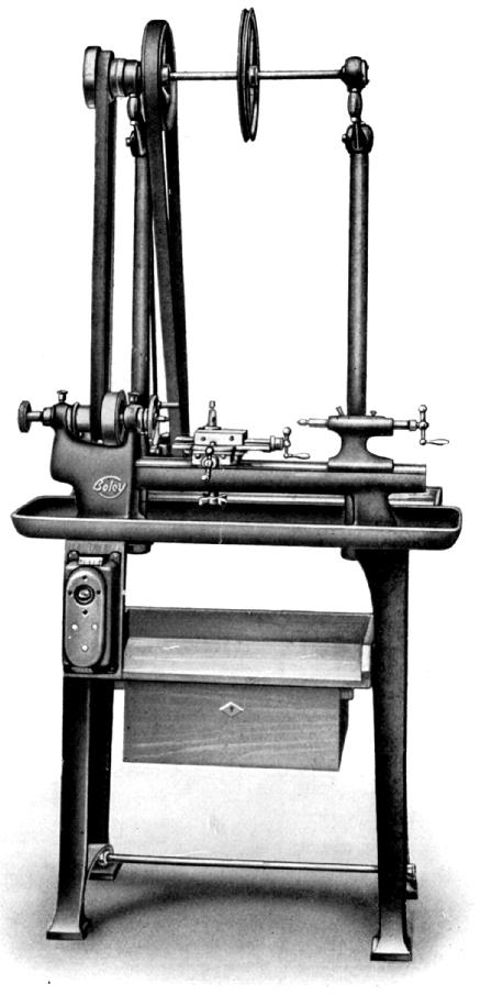
Boley stand g16 for independent electric drive. This was very similar to the g12 and g14 stands but with the addition of a pair of columns, fixed by brackets to the rear of the chip tray. The columns carried a shaft, running in ball races, that drove the headstock spindle pulley and could also be adapted for driving toolpost-mounted high-speed grinding and milling attachments. Rather oddly, instead of extending the cast-iron chip tray rearwards to carry the electric motor, a wooden tray was added for this purpose. |
||
|
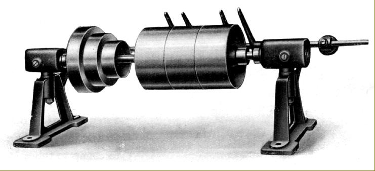
Boley countershaft H4 - an entirely conventional unit with "fast-and loose" pulleys and running in self-aligning, oil-ring bearings. The unit was also built in an H2 version with one fast and one loose pulley - and could be fitted with a round-rope pulley (from 300 to 350 mm in diameter) to drive toolpost-mounted accessories The wide central pulley was free to rotated on the shaft with the outer pair each driven by its own flat belt - each at either a different speed, or arranged to run in opposite directions. As the striker forks shifted the belts across the lathe spindle was caused to change speed - or instantly reverse. |
|
Boley 2-speed or reversing countershaft 1634 for clamping to a tube. This fast-and-loose assembly picked up a 25 mm wide flat-belt drive from the line shafting and transferred it to a 5-step pulley that took a round leather rope. By using tubes as part of the mounting system the countershaft could be quickly and accurately aligned with the machine below. This unit had oil catches beneath the bearings - ideal if a rigorous schedule maintenance was in place, but whose usual effect was to fill and drip. They also gave the poor lubricant man yet another job - mopping them out before refilling the oil wells. |
|
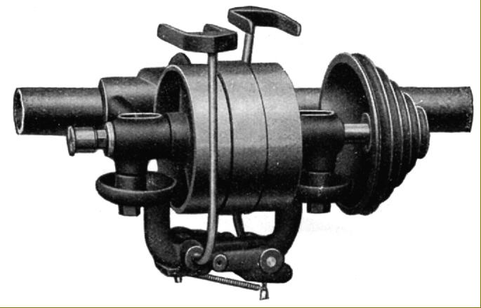
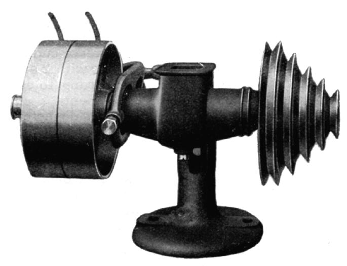
Boley Universal Countershaft 1636 for bench or wall mounting. With a modified foot the unit - under part numbers with a suffix R - could be carried on a tube. It was made in various sizes with spindles from 10 to 18 mm in diameter and belt pulleys 25 mm wide in 80 and 100 mm diameters with a 4-step round-rope drive or, as illustrated, with a 35 mm wide drive belt, a 150 mm diameter driven pulley and a 5-step output drive. |
|
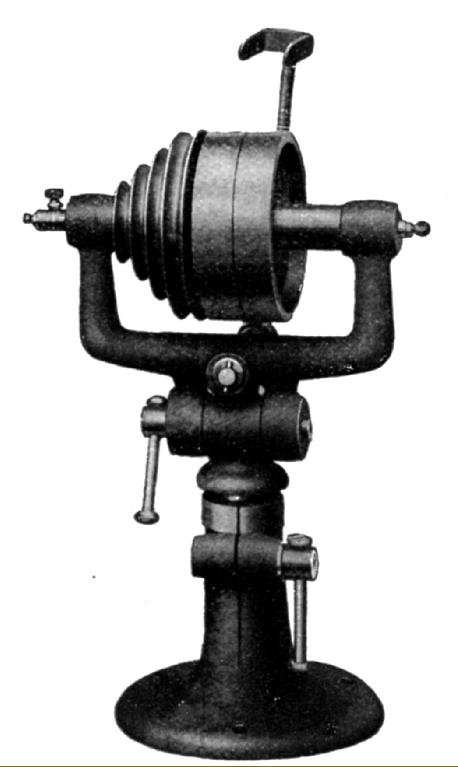
Boley multi-way adjustable countershaft No. 1631 for round belts with flat-belt fast-and-loose drive with 80 mm diameter and 20 mm wide pulleys. Another model, the 1633 was available to take 25 mm wide belt. The unit stood 310 mm high. |
|