 |
|
|
|
|
|
|
|
|
|
|
|
|
|
|
|
|
|
|
|
|
|
|
|
|
|
|
|
|
|
|
|
|
|
|
|
|
|
|
|
|
|
|
|
|
|
|
|
|
|
|
|
|
|
|
|
|
|
|
|
|
|
|
|
|
|
|
|
|
|
|
|
|
|
|
|
|
|
|
|
|
|
|
|
|
|
|
|
|
|
|
|
|
|
|
|
|
|
|
|
|
|
|
|
|
|
|
 |
|
|
|
|
|
|
Boley Lathe No. 1a. A typical Boley WW-Type watchmaker's lathe with a centre height of 50 mm, 110 mm between centres and a single foot. The headstock spindle was hardened and ground, fitted with hardened and ground precision bearings and the pulley provided with a ring of indexing holes located by a plunger visible at the left hand end of the headstock. A miniature compound screw-feed slide was available to special order - as was a wide range of other finely made accessories including capstan conversion parts.
|
|
|
|
|
|
|
|
|
|
|
 |
|
|
|
|
|
|
Boley Lathe No. 1b A longer version of the A, with 230 mm between centres, this lathe was fitted with a screw-feed compound slide rest and two bed supports as standard.
|
|
|
|
|
|
|
|
|
|
|
 |
|
|
|
|
|
|
Boley Lathes No. 2a (also 3a and 4a with increased centre height)
Heavier still, with a 65 mm centre height, the 2a was available in several versions named according to the type of countershaft used. The Boley 2 lathe was fitted with a screw-feed compound slide rest as standard .
|
|
|
|
|
|
|
|
|
|
|
 |
|
|
|
|
|
|
|
|
|
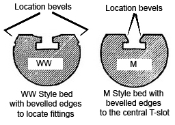
Boley watchmakers' lathes can be found with two "styles" of WW (Webster Whitcombe" bed: the traditional type and a modified version where the alignment of the headstock, tailstock and other fittings relied upon an "M" type with bevelled-sided T-slot
|
|
|
|
|
|
|
|
|
|
|
|
|
|
|
|
 |
|
|
|
|
|
|
Note quite what it seems….
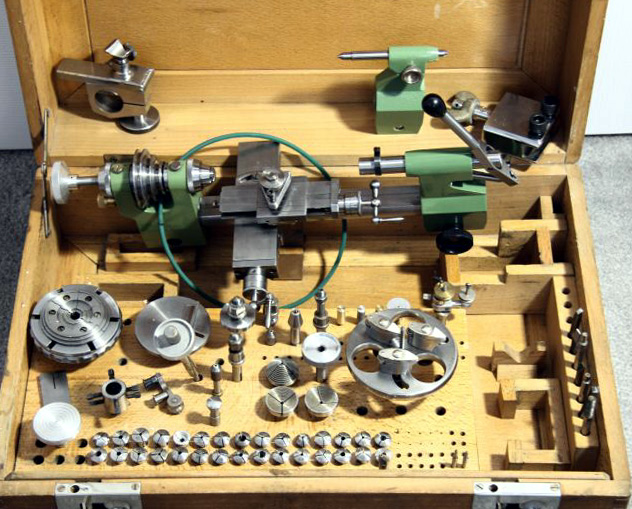
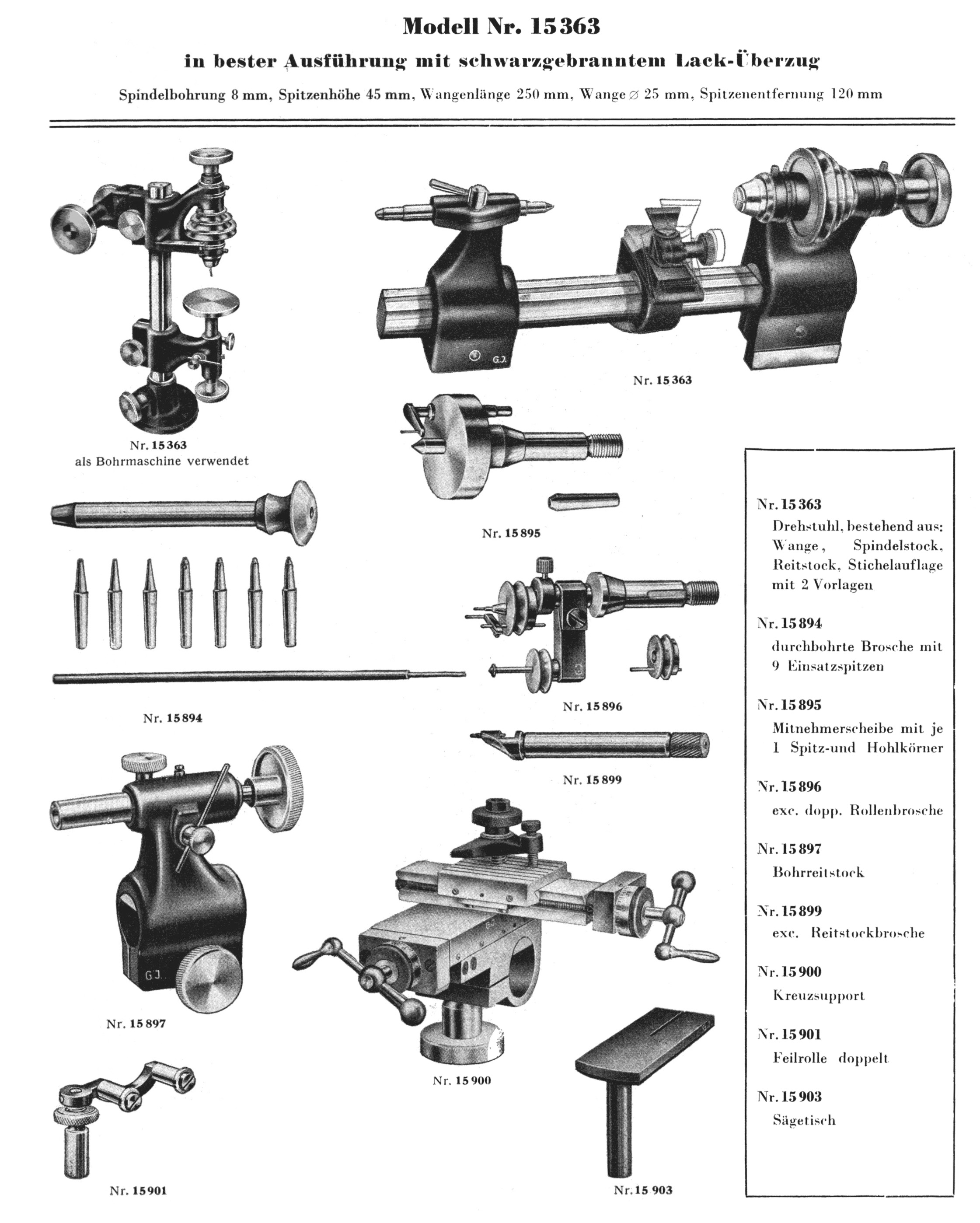
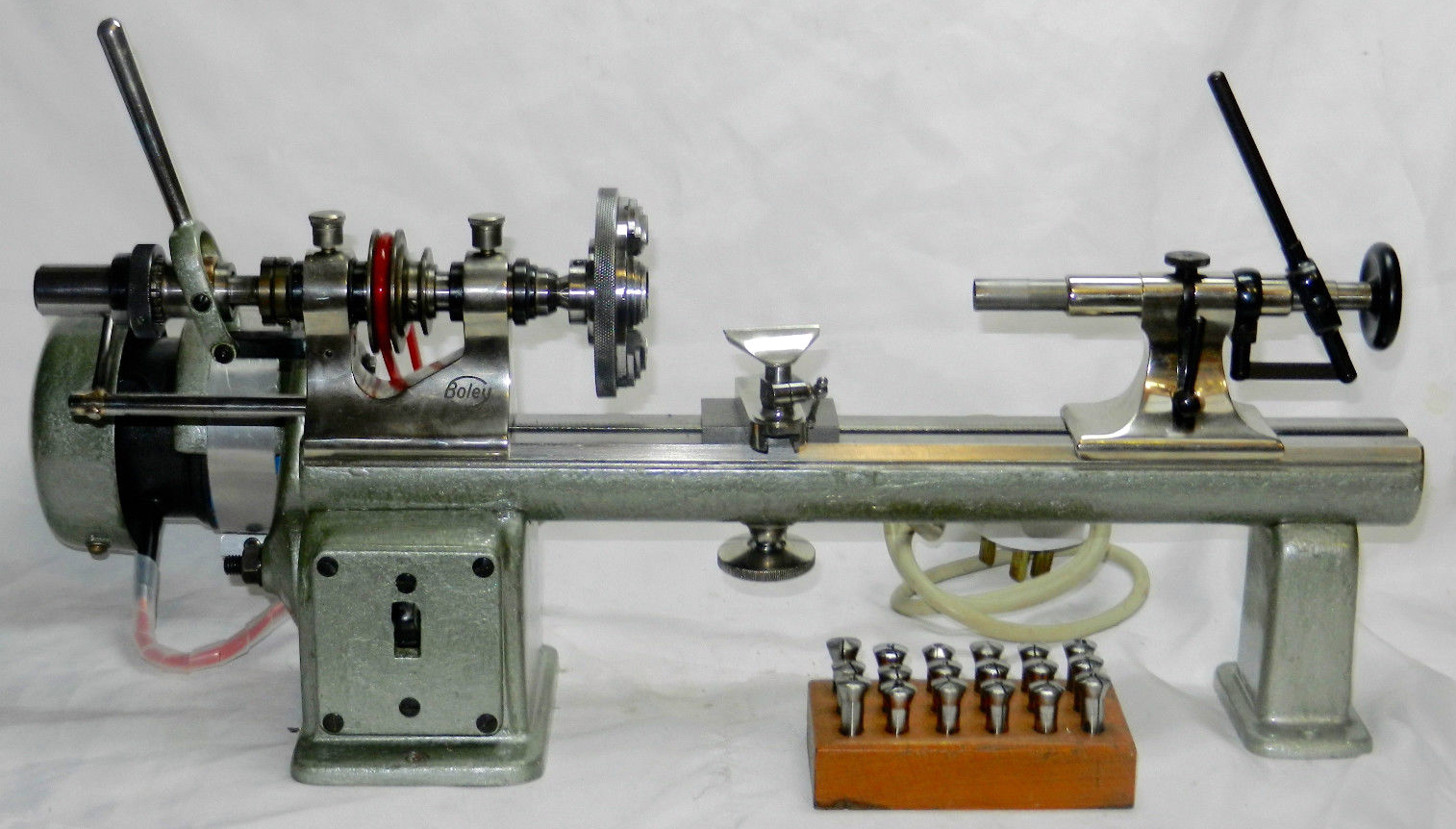
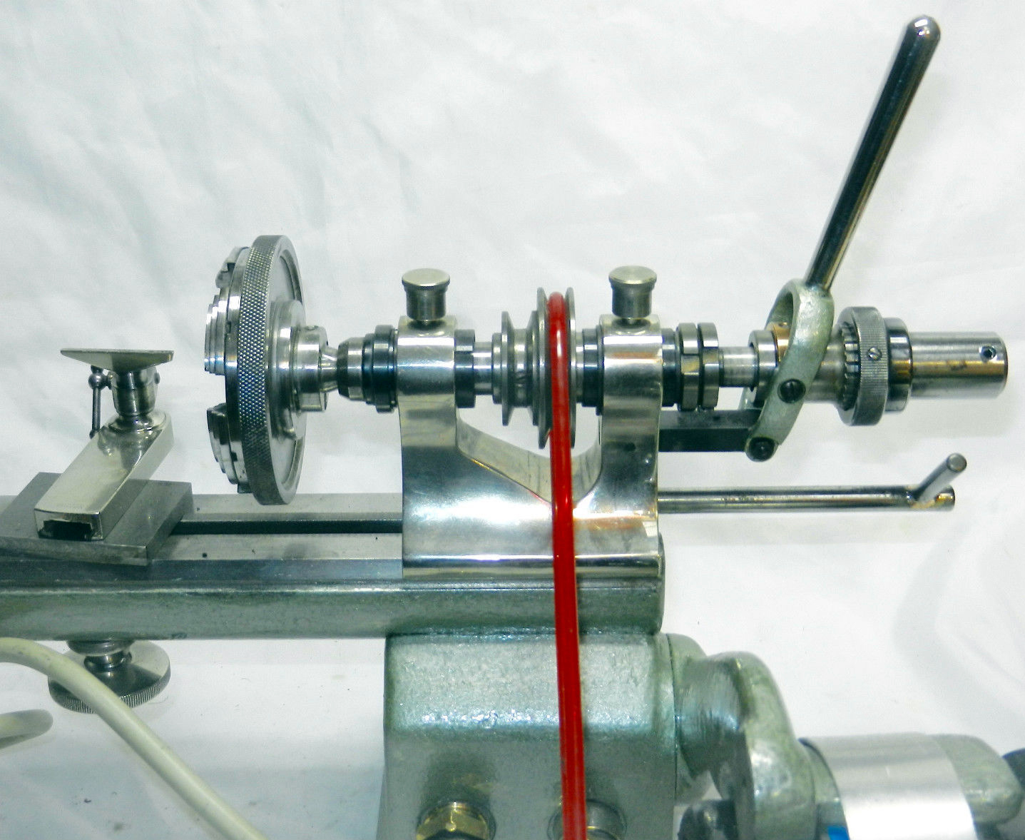
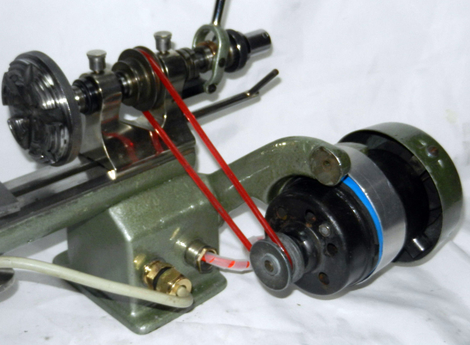
Although very late model Boley WW type watchmakers lathes had painted headstocks and tailstocks the example shown here - though clearly stamped Boley on the end of the bed - has a bed diameter of 25 mm - whilst all known genuine Boley-made versions are 19 to 20 mm. It was produced by a maker of watch and clockmakers' equipment based in the communist German Democratic Republic (GDR) Andrä & Zwingenberger from the 1950s until the late 1960s (or even 1970s). The lathes were of heavier-than-normal construction (reference the 25 mm diameter bed ) - and usually offered as a complete, boxed kit at a bargain price - the aim being to acquire Western currency at almost any cost. Unlike most other watchmaker's lathes paint (beautifully applied) was used on headstock and tailstock - again mimicking the last of the Boley WW lathes made during the 1950s.
The lathe was marketed world-wide, with the East German dealers Georg Jacob perhaps responsible for stamping the end of the bed G. Boley - though with a lack of finesse, the heavy punching and thicker letters too close together betraying the origins of the lathe.
A recent examination by its new owner has revealed that the 45 mm by 130 mm lathe, bought second-hand, has collets and step-chucks stamped variously Lorch, Boley and Boley & Leinen - a not-unusual experience with watchmakers' lathes. However, the solid white oak varnished case has finger (box) joints and panel construction for the top and bottom with very interesting pivoting latches that are flush with the front side when closed - so allowing a very safe, positive locking.
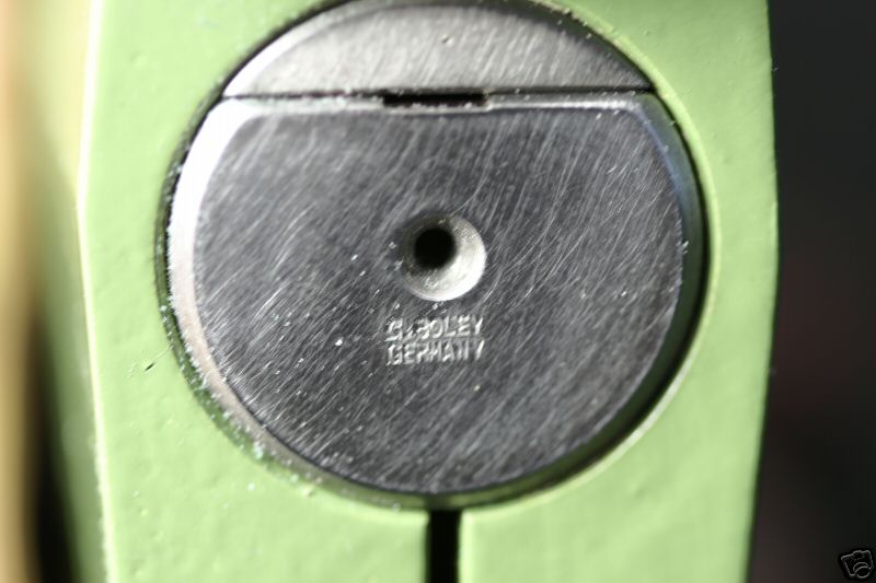
A little short of 260 mm long by 25 mm diameter (measured at 24.99 mm) the lathe bed is mounted on a nickel-plated foot with two 8 mm hex cap screws to secure the headstock and a 12.6 mm bolt and wing nut to clamp it to a bench. The bed is made from a solid bar of polished steel with a flat on top and grooved along the full length of the center line. It is stamped "G. Boley Germany" at one end while the other has a centre hole - with another hole lower down for an unknown use. The same name stamp can also be found on the base of the hand- rest base and underneath the saw table.
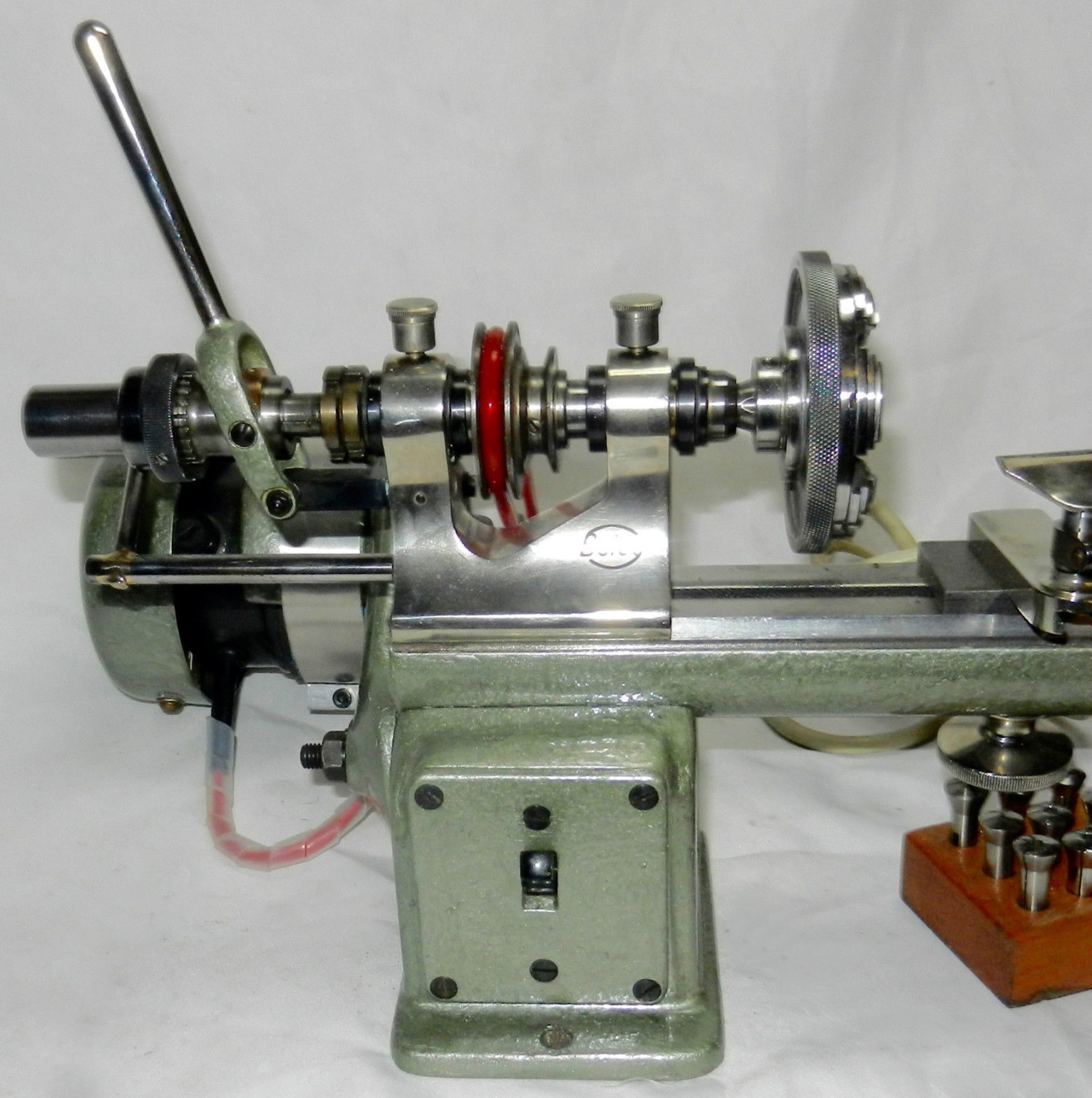
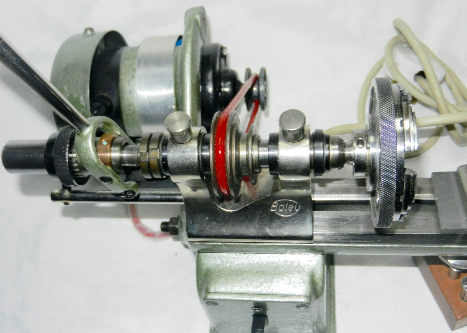
With an immaculate green paint finish the lathe uses a cast-iron headstock with an 8 mm bore spindle to take 8 mm collets secured with a steel draw tube having an aluminum handle. On the outer flange of the 3-step drive pulley is a circle of 60 division holes (with four larger holes evenly spaced every 15 to index a square) and indexed with the usual spring detent pin. The spindle bearings are plain bronze with ring-type adjusting nuts.
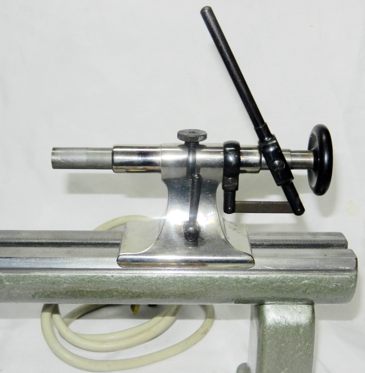
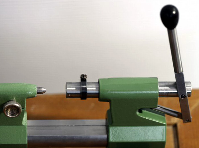
Two different cast-iron tailstocks, with black aluminum tightening nuts, are included with the lathe. The ordinary fixed version has the usual double-ended spindle, with male and female centers, whilst the drilling tailstock operates smoothly, has its own draw-in collet closer, an absolute maximum travel of 40 mm and a V-groove on the underside to prevent rotation. The adjustable (blackened steel) ring with screw lock located on the left side - though how this could be effective is difficult to see - a better position would be on the right hand side, between the tailstock body and the handle to limit travel.
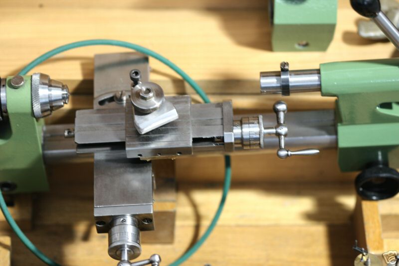
Built with a traditional dovetail construction and screw-adjusted gib-strips - just 2 screws for the top slide but 6 for the cross slide - the compound slide rest is well made and has a smooth, even silky, feel. The 0.8 mm pitch feed-screws run through bronze nuts and are equipped with 0-40 divisions (= 0.02 mm per division) and neat, zeroing micrometer dials with friction locking. Useful travel of the top slide is estimated at 50 mm and 35 mm for the cross slide.
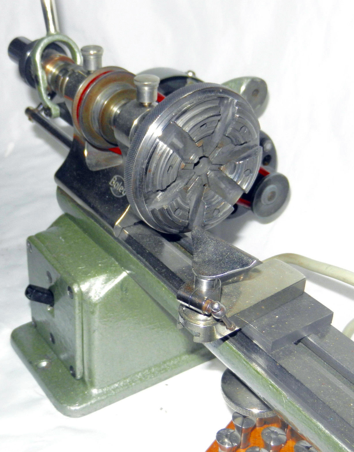
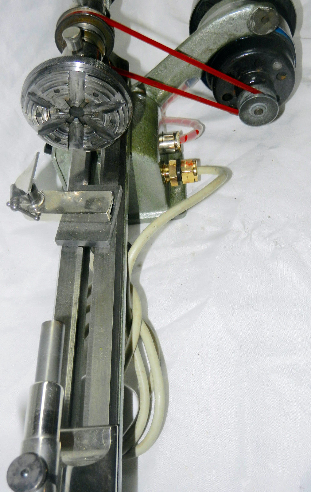
Included in the accessory kit are a number of useful items - through the tip-over T-rest does not match its base with any great accuracy and the two parts may well be of different origin as the filing roller-rest and saw table (20 by 40 mm) do not fit the hole - being larger by some 0.275" on the diameter of their support bars. Of 59 mm diameter the plain faceplate has one axial slot and adjustable angle plate, 44 mm long by 10 mm by 10 mm. The 85 mm diameter three-jaw faceplate is supplied with its own draw bar with a spring-center finder. the universal 68 mm diameter self-centering 3-jaw chuck can grip pieces internally and externally. The pivoting attachment appears to be of good quality as does a tailstock broche - the same as Nr. 15896 and 15 899 Georg Jacob model respectively. A number of collets, ring chucks, wax chucks and arbors complete the set.
If any reader can offer further insights into Andrä & Zwingenberger and their products the writer would be pleased to hear from you..
|
|
|
|
|
|
|
|
|
|
|
|
|
|
 |
|
|
|
|
|
|
1957 Catalogue from Georg Jacob showing the lighter-patter "Geneva" lathe
|
|
|
|
|
|
|
|
|
|
|
|
|
|
 |
|
|
|
|
|
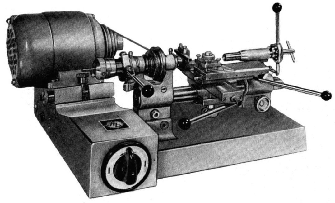
An all-lever-feed production version of the East German "Model 15363" dating from 1976 and arranged on a self-contained motor-drive and base unit.
|
|
|
|
|
|
|
|
 |
|
|
|
|
|
|
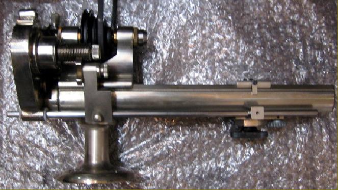
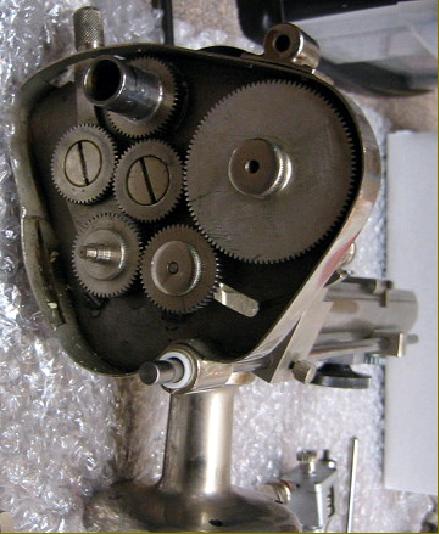
A very unusual G. Boley watchmaker's WW lathe with chase-type screwcutting driven by enclosed gearing that incorporated a tumble-reverse mechanism. While the principle was ordinary, the mechanical arrangement, and the shielded gears, are a set-up though to be unique on this class of lathe.
|
|
|
|
|
|
|
|
 |
|
|
|
|
|
 |
|
|
|
|
|
|
|
|
|
A genuine late-model G.Boley WW-type watchmakers' lathe from the 1950s with
built-in switchgear, built-on motor, and lever-action to the collet closer and tailstock spindle.
|
|
|
|
|
|
|
|
|
|
|
|
|
|
|
|
 |
|
|
|
|
|
 |
|
|
|
|
|
 |
|
|
|
|
|
|
|
|
|
|
|
 |
|
|
|
|
|
 |
|
|
|
|
|
 |
|
|
|
|
|
|
|
|
|
|
|
 |
|
|
|
|
|
 |
|
|
|
|
|
|
Late-model "Boley": the screw-feed compound slide rest followed the rest of the lathe in being of heavy construction - with generous amounts of travel - and 40 divisions on the metric micrometer dials.
|
|
|
|
|
|
|
|
 |
|
|
|
|
|
|
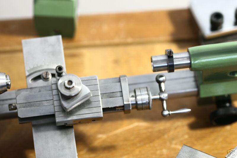
Parallel lines engraved on the top-slide tool clamping area are an immediate identification point
|
|
|
|
|
|
|
|
|
|
|
|
|
|
 |
|
|
|
|
|
 |
|
|
|
|
|
|
The lack of finesse in the "G.Boley" stamp - heavy punching with the heavy letters too close together - betrays the origins of the lathe
|
|
|
|
|
|
|
|
|
|
|
|
|
|
|
|