email: tony@lathes.co.uk
Home   Machine Tool Archive   Machine-tools Sale & Wanted
Machine Tool Manuals   Catalogues   Belts   Books  Accessories

Denford Viceroy Variable-speed
Drive Lathes:
Synchro, 280, 280VS, Enterprise
Micromatic, Inchmetric & 280VB

Viceroy Home Page   Viceroy Synchro, 280 & Enterprise Lathes
   
Viceroy Wood Lathes   Viceroy Milling Machines   Viceroy Shaper

T.D.S.-1.L.S., T.D.S.5.G.B., T.D.S.3.M.W. Educator & Types 240 and 250

Viceroy Drills   T.D.S. 5 GB Photo Essay

Handbooks and Parts Manuals are available for
most Viceroy Metal Lathes, Viceroy Wood Lathes 
and Viceroy (AEW) Milling Machines and
other Viceroy Publications

From rather more humble beginnings with their TDS lathes, in later years Viceroy introduced a number of infinitely variable-speed drive lathes, the first of these being, in the early 1970s, the "Varispeed" electronically infinitely variable-speed Model TDS 1/1 GB V.S. - this being, almost certainly, the rarest of several other seldom-found Viceroy models. Of identical mechanical specification to the ordinary TDS 1/1 backgeared and screwcutting types, in place of the normal V-belt drive by countershaft, the Vairspeed used a powerful 1 h.p. shunt-wound, thyristor-controlled DC motor that gave infinitely variable speeds from 200 to 2000 r.p.m. in direct drive by a toothed belt and in backgear from 25 to 200 r.p.m. - a most useful speed range for either beginner or expert. Speed control was by dial selector with a surrounding spindle-speed ring, this being mounted in a convenient position at the top of the headstock's front face.
However, the
Varispeed was not a discrete model, but an add-on drive system that could be fitted to any of the T.D.S. models, those listed at the time being the T.D.S. 1/1 GB (screwcutting gearbox and power cross feed); the T.D.S 1/2P.C.S (screwcutting with a simple 2-speed feed box and changewheels and power cross feed); the T.D.S. 1 LS (screwcutting by changewheels only and hand-operated cross-feed); the T.D.S. 5B.G. (a simple, plain-turning, backgeared but non-screwcutting primary training lathe) and the T.D.S.3M.W. (a combined metal and wood lathe that could be specified by the customer in several forms including with backgear and power sliding feed). However, not a single example of a lathe equipped as a Varispeed has yet to be found so, if you own one, the writer would be interested to hear from you.
Following the
Varispeed, a group of specially-developed 5.5" x 24" lathes known as the 280, 280VS, Synchro, Enterprise 280/280VS and "Micromatic" were announced, the last mentioned being fitted with a simple CNC control system. The "Enterprise" badge was used on export models while the "Synchro" label appears to have been applied almost indiscriminately, the model name having no apparent connection with a particular specification. The 280-Series lathes, with a 0.5" increase in centre height, were a further improvement on the already well-specified and long-established belt-change versions and all were designed to be "easy-to-use" machines. Controls were conveniently to hand and speed and thread-selection levers required no releasing pins or clamps to be removed or reset before they could be moved. Two types were made: rear-drive and under-drive; while the former could, in theory, be supplied for bench mounting, they were always fitted to a robust, welded-steel cabinet with chip tray, splash back, safety interlocks on the covers and the option of built-in coolant equipment. The speed-change system was of the mechanical type with a wide transmission belt running between pairs of balanced cast-iron pulleys, one set of which moved further apart whilst, simultaneously, the other two came closer together - so giving an infinitely variable drive ratio. Although most models had their moving variable-speed pulleys operated manually, some Synchro versions were fitted with an electric motor operating through worm-and-wheel gearing with control by either push-buttons or a joystick. Interestingly, the motor used on this drive is wired "Delta" and marked 220v - but fed with 440 volts; this being done, apparently, to give the motor sufficient power to overcome a significant amount of friction in the mechanism controlling the expanding and contracting pulley as they approached the maximum-speed setting (experiments feeding the motor with 220V have shown that, if so supplied, it does not have the power to operate properly.
Because several versions of these lathes were made, and some models appear to be mixtures of different specifications, it is not possible to be categorical about fixtures and fittings (even the factory was confused after few years as to what had been built and when) and so the following must be taken as a general guide.
Schools, training departments, prison workshops and similar establishments were good customers for the 280 Synchro models and some were ordered thoroughly well equipped (after all, it was only tax-payers' money) with rear-mounted powered vertical-milling attachments, chrome-plated bedways, T-slotted boring tables, full collets sets, steadies and quick-set tooling commonly being found. The writer has, in the past, found examples still unused in storerooms a good thirty years after being put there and, although this supply has dried up, numbers of these machines are to be found on the second-hand market and, while often lightly used, are sometimes damaged due to mishandling of the controls, especially the gearbox. The introduction of these lathes coincided with a raft of burdensome new Health and Safety regulations, workshop administrators and teachers readily admitting that this caused them to simply remove all machining from the curriculum and substitute sitting-at-a-desk theory lessons. As a consequence, as workshops were redeveloped to promote Mickey Mouse engineering and Chinese-made snap-together assembly kits, even more unused or merely test-run  examples of these lathes came onto the market. Naturally, these ex-training machines represented tremendous value for money (especially to keen-eyed dealers) - though not for the poor taxpayers who funded both their purchase and the salaries and gold-plated pensions of the jobs-worth bureaucrats who then effectively forbade their use.
Continued below:

The rare Viceroy Varispeed version of the TDS 1/1 GB lathe

A splendidly original Viceroy 280 Synchro with the
"indented" 12-speed headstock-mounted speed selector

Continued:
Although clearly designed with the educational market in mind, the makers did not cut any corners with regard to longevity - the headstock, screwcutting gearbox and apron were all lubricated from oil sumps, with level windows to clearly show the state of the supply. The headstock, in the form of a tall but very short, open-topped box, carried a No. 4 Morse taper, 1.1-inch bore spindle running in Timken taper roller bearings and fitted, in some cases, with plastic (Delron) backgears.
WARNING: the writer has reports of owners using the wrong lubricant with the result that the gears can swell up, jam and break. In one case, even though the supposedly correct (replacement) oil was supplied it still caused the problem. The 280VS and Synchro were always advertised as having a D1/3" Camlock spindle nose (instead of a thread) and, unlike the threaded nose versions, did not need the strong "hinge-over" spindle lock to remove chucks and faceplates (though some machines were still so fitted).  Slow speeds on the 280VS were provided in two ways: one (with the motor and its variable-speed drive pulleys mounted behind the headstock) was entirely conventional, with a strongly-built backgear assembly engaged through a self-releasing and locking mechanism with a single-lever control. The other (with the motor and drive inside the cabinet base) was unusual: the output shaft from the variable-speed drive carried a small poly-V pulley that drove to a countershaft set above it. From there small and large Poly-V pulleys took the drive to large and small pulleys on the headstock spindle. Sitting between the headstock pulleys was a heavily-built, double-ended dog clutch, operated by a lever on the face of the headstock, that allowed either drive to be engaged instantly. Although the latter system was very quiet in operation, the use of a belt (rather than gears), meant that the reduction ratio achieved was not as great - nor could it transmit as much torque to tackle really heavy, large-diameter jobs. As far as is known the version with electrical control of the expanding and contracting pulleys was always built with its drive system mounted behind the headstock.
Fitted as standard with a 1500 r.p.m. 3-phase 1.5 h.p. motor, spindle speeds ran from 70 to 400 r.p.m. in low range and from 400 to 1600 r.p.m in high (but see comments at the bottom of the page).  The pulleys and their-shifting mechanism were very heavily built, to eliminate flex, and give a positive feel to the controls - either a headstock lever or stand-mounted wheel. Marking accurate speeds on variable-speed systems is always difficult and on the version with a manually-operated headstock lever this was achieved by arranging for it to index through a series of spring-loaded, indented positions, marked with the expected revolutions.  Versions with electrical control (and the Poly-V-drive model that used a stand-mounted handwheel) had their spindle speed displayed on a digital read-out.
Continued below:

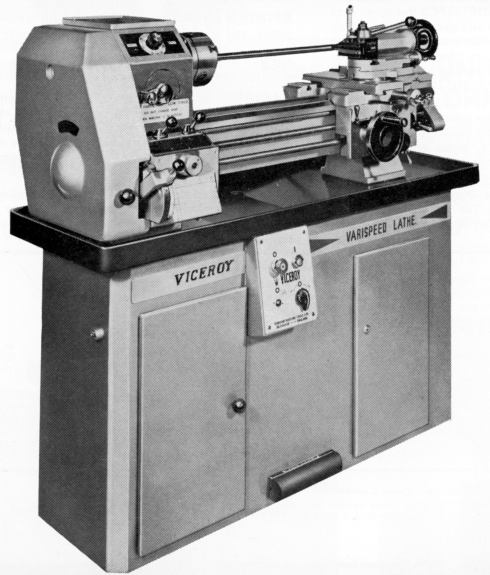
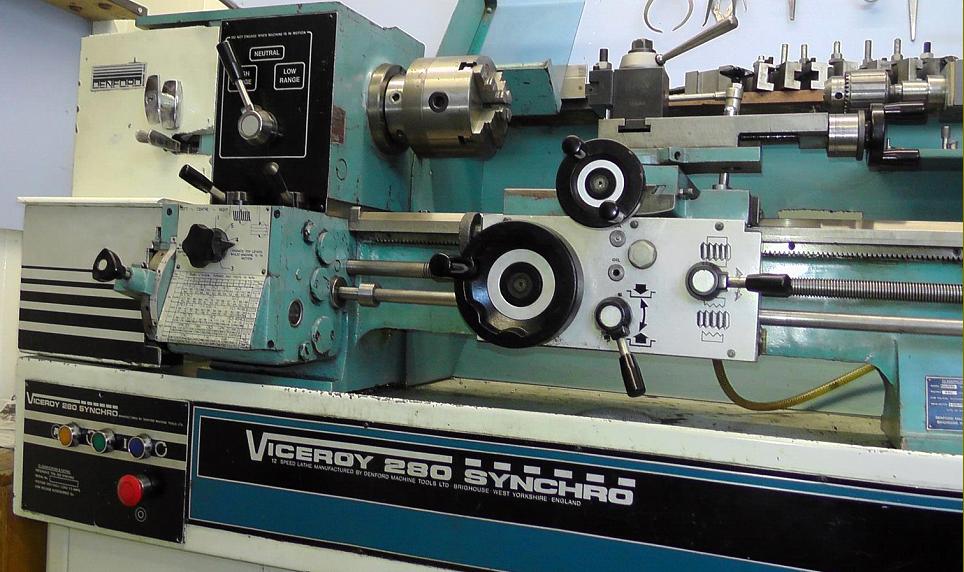
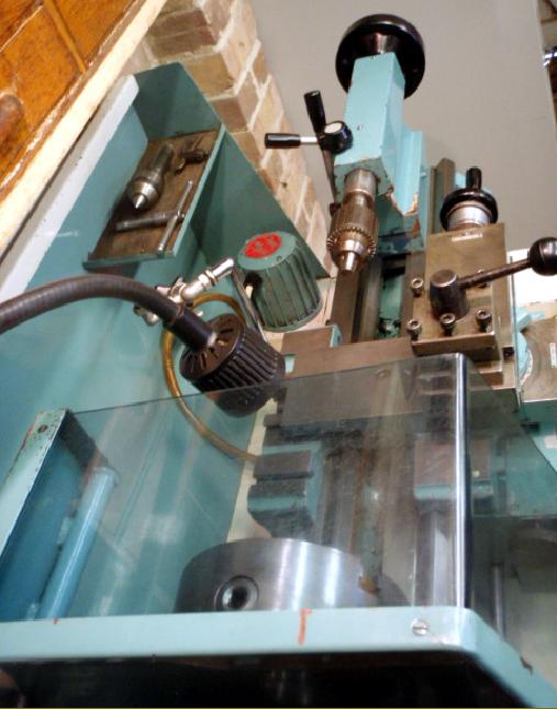
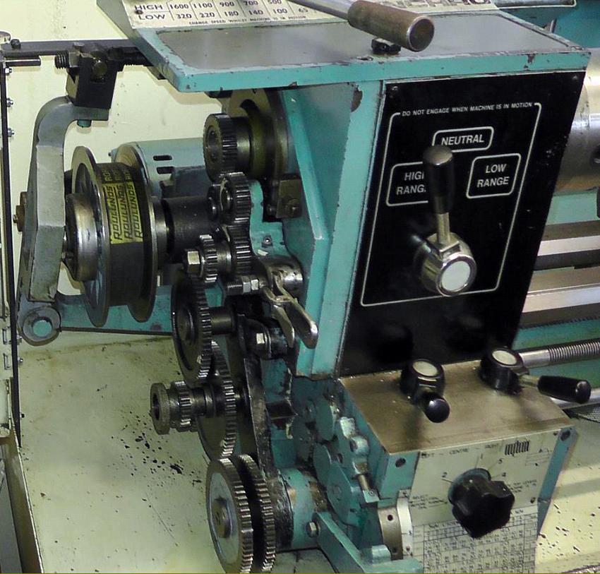
Inside the headstock of the unusual Poly-V drive Viceroy 280VS. The serrated ring on the right is part of the pulse generator system for the digital speed read-out
Continued:
Design and location of the electrical-control panels varied widely; in general, those with electrically-operated pulleys had a pendant unit fitted above the headstock combined with stand-mounted controls (either in the centre or below the screwcutting gearbox) and usually shown on etched aluminum panels; others had controls confined to the stand. Many lathes, especially those purchased for training workshops, were fitted with an unreliable, full-length pneumatically-operated foot switch fitted to the front of the stand at floor level.
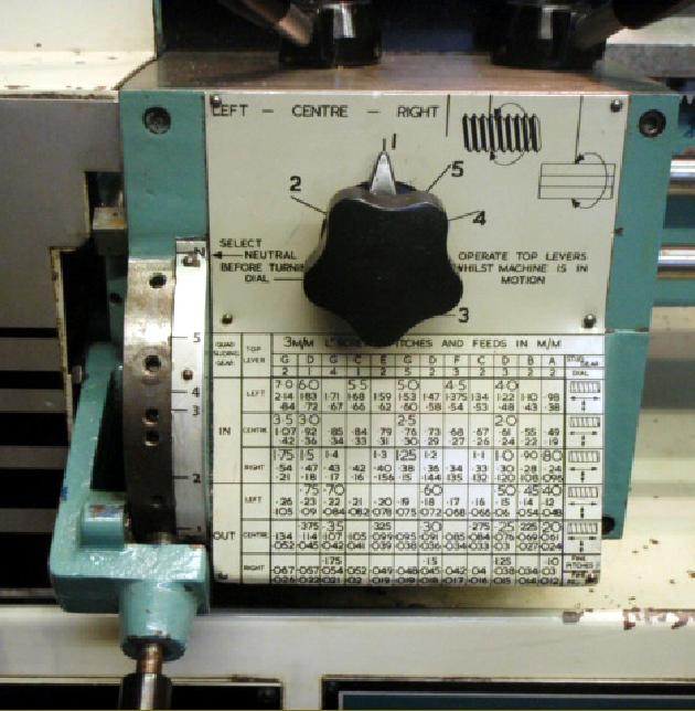
The screwcutting gearbox drove either a 3 mm or 8 t.p.i. leadscrew (with needle-roller thrust bearings) and a separate power shaft, the latter usually (but by no means always) fitted with a most useful automatic disengage to the saddle drive. The gearbox was a comprehensive affair with multi-lever operation, some of which had to be moved with the spindle stationary and others when it was turning and the changewheels in mesh - the arrangement allowing an instant change of sliding or surfacing speed. However, before operating the gearbox in this way a careful reading of the maker's operating instructions is essential: it is not safe just to play with the levers with the lathe running and "see what happens" - what "happens" may shatter the gearbox. On the metric box 72 pitches were available from 0.2 to 7.0 mm and on the English box 48 from 4 to 224 t.p.i. Feeds along the bed ranged from 0.03 mm to 2.14 mm or 0.0014" to 0.030" per revolution of the spindle.
Following previous Viceroy practice, the compound slide rest assembly used the old-style feed screws and nuts - but with the top and cross slide castings squared-off to give a more modern appearance. One point worth mentioning is that some machines have not two but three socket screws to lock the top slide to the cross slide: the missing screw is hidden away at the front of the casting - and not mentioned in the original handbook. While some saddles had plain wings most incorporated "as-cast" T slots in the rear pair that allowed, for example, a travelling steady to be mounted, a toolpost for turning at the extremes of the machine's capacity, jobs to be bolted down for machining by cutting tools in the chuck or coolant pipes clipped in place . 
While most 280 lathes had metric cross and top-slide feed screws, a few were produced to inch specification and some carried dual dials, with metric on the inner ring and inch on the outer. The tailstock was particularly strong and, because it carried a No. 3 Morse taper, drill shanks were far less likely to slip and ruin the spindle. All the handwheels - carriage, compound slide rest and tailstock - were in metal with a durable plastic coating, but retained by cheap and nasty spring-dowel pins.
Late-model Viceroy lathes offered a generally good quality of construction and a very decent specification that - while not up to the standard of a Colchester Chipmaster - was available at a considerably lower price and represented excellent value for money. Little-known and underrated, they offer terrific value second-hand.
If you have one of these lathes and its specification differs from those described, the writer would be interested to hear from you..
An owner writes with some most interesting and educational points
Now I've owned and used my 280 Synchro for nearly a year, can I offer a few comments to add to your own on the topic?
Generally, I like it a lot, it's accurate, relatively quiet, except at the highest speed setting, thanks to a combination of belt primary drive and steel/Delron back gears, and (for a home-workshop lathe) can take off serious amounts of metal. Mine is 3-phase, run off an elderly inverter and is the model with 12 speeds controlled by the lever at the top, so I don't have any issues with the 3-phase speed control motor which the VS model is prone too when inverter driven.
Actual spindle speeds are not what Denford claim them to be. The variable-speed pulley set up appears to be exactly in accordance with the factory drawings and there is no evidence that they have been 'messed with', but the resulting speeds differ from those stated on the machine plate which are 65, 100, 140, 180, 220 and 320 in low range and 380, 500, 700, 900, 1100 and 1600 in range. Even these differ from the Denford literature which claims 70-260 in low and 400 -1600 in high. Given a back gear ratio of 5.09-1, and taking the lowest speed as 70, which is the lowest I can get, then the lowest speed in high range must be 356, which doesn't correspond with either of the Denford figures. The best I can do, from a starting point of 70, is 70, 90, 120, 145, 175 and 225 in low range and 360, 460, 550, 745, 900 and 1150 in high range. My rev counter flickers a little, so it may be a few revs either side of this, but not enough to account for the difference. Yes its possible to get a higher top speed by adjusting the pulleys, but at the expense of raising the lowest speed correspondingly. Anyway, 70 - 1150 is fine for what I do, and when eventually my old inverter, which doesn't have speed control, gives up the ghost, it will be replaced by a modern one which does, so the whole thing becomes academic. The saddle has power sliding and cross feed, and the engagement/disengagement is very light even under load. A surprising omission for a machine built around 1980 is that the saddle is not fitted with 'wipers' to keep the dirt out of the slides, and this appears to have been common across the whole Denford range.
Like late model TDS1 lathe, the Synchro is fitted with a safety auto trip on the longitudinal feeds, and this seems to work well, though Denford emphasise that it's only a safety device and not to be used as an auto-stop mechanism during regular work. For accurate working to a shoulder an adjustable carriage stop is used. Curiously, according to the Denford Forum for all Viceroy lathes, some TDS 1 machines had an auto knock off on screwcutting as well, but as this worked by means of a rack mechanism opening the half nuts, and taking about 1/2" of travel to do so, this must only have been intended as a safety device, and not as Denford's equivalent of the Ainjest, for rapid thread cutting up to a shoulder. As yet I haven't heard of a 280 with this feature, but as the aprons appear identical, I can see no reason why not.
I like my 280  very much, and consider it to be solid and well built, and I can't understand why they don't seem as popular in the second-hand marketplace as the equivalent Boxford lathes, let alone the fabled Myford 254 or 280. My Denford, with a full set of chucks, faceplate, catchplate long slotted cross slide and both steadies, from a well known commercial dealer, delivered to my door, was less than 1/4 of the price the Myfords seem to fetch, if and when they ever come on the market..

On the Poly-V drive version of the 280VS the high-low range indicator made no mention of the necessity to engage gears.
The screwcutting gearbox was adorned with instructions and essential warnings

The drive system of the unusual 280VS model was contained within a very strong (but crudely-finished)  frame constructed from solid rectangular-section steel bolted to the inside back face of the cabinet stand. The shafts were held in self-aligning plumber blocks and, to allow the tension of the final drive belts to be set, the frame could be adjusted vertically by pusher screws at top and bottom.

Connection of the flexible-drive cable to the operating
arm that opened and closed the variable-speed pulleys

Handbooks and Parts Manuals are available for

most Viceroy Metal Lathes, Viceroy Wood Lathes

and Viceroy (AEW) Milling Machines and

other Viceroy Publications

Viceroy Home Page   Viceroy Synchro, 280 & Enterprise Lathes

Viceroy Wood Lathes  Viceroy Milling Machines  Viceroy Shaper

T.D.S.-1.L.S., T.D.S.5.G.B., T.D.S.3.M.W. Educator & Types 240 and  250

Viceroy Drills   T.D.S. 5 GB Photo Essay

Denford Viceroy Variable-speed
Drive Lathes:
Synchro - 280 - 280VS - Enterprise -
Micromatic Inchmetric 280VB

email: tony@lathes.co.uk
Home   Machine Tool Archive   Machine-tools Sale & Wanted
Machine Tool Manuals   Catalogues   Belts   Books  Accessories