 |
|
|
|
|
|
|
|
|
|
|
|
|
|
|
|
|
|
|
|
|
|
|
|
|
|
|
|
|
|
|
|
|
|
|
|
|
|
|
|
|
|
|
|
|
|
|
|
|
|
|
|
|
|
|
|
|
|
|
|
|
|
|
|
|
|
|
|
|
|
|
|
|
|
|
|
|
|
|
|
|
|
|
|
|
|
|
|
|
|
|
|
|
|
|
|
|
|
|
|
|
|
|
|
|
|
|
|
|
|
|
|
|
|
|
|
|
|
|
|
|
|
|
|
|
|
|
Launched in the early 1950s, and built in the Cincinnati Lathe & Tool Company factory in Wilmington, Ohio, the original Toolmaster was intended to compete with the outstandingly successful ram-head Bridgeport Series 1. However, with its non-nodding head - and hence greater rigidity than the Bridgeport - it sacrificed some versatility in favour of strength and was thus ideal for heavier work, especially (in the opinion of experienced operators) any type of boring. The Toolmaster was built in Series 1 form with "rounded" styling and then, from the early 1970s onwards in France, as the Types DD and MT - both with more modern "angular" lines.
Round-style Models
Offered as a range of six models, the: 1-A, 1-B, 1-C, 1-D, 1-E and H-V, some confusion exists between the maker's catalogues and maintenance manuals concerning the exact type designations. However, it would seem that, upon placing an order, customers were invited to assemble a machine from various standard components - column, knee, table and head and ram - to arrive at the desired specification. It is thus likely that used machines may not correspond exactly with the following details - though it should be possible, with a close examination, to determine exactly what is on offer. By the mid 1950s the range had grown to include all the previously-mentioned round-style types, with all employing an identical column (item 6JH), knee (item 6JK) and table assembly (item 6JH) - the only differences between them being in the type of head fitted.
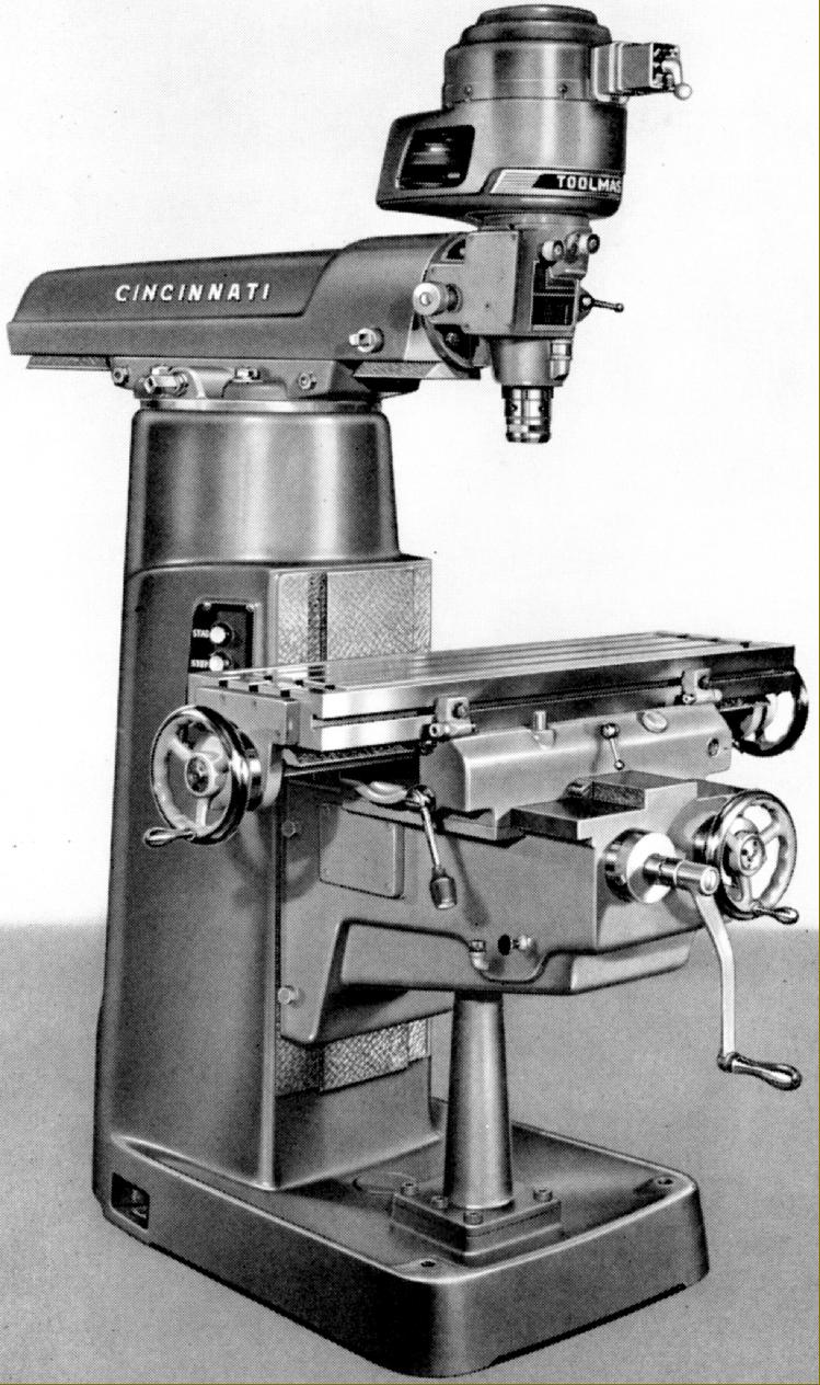
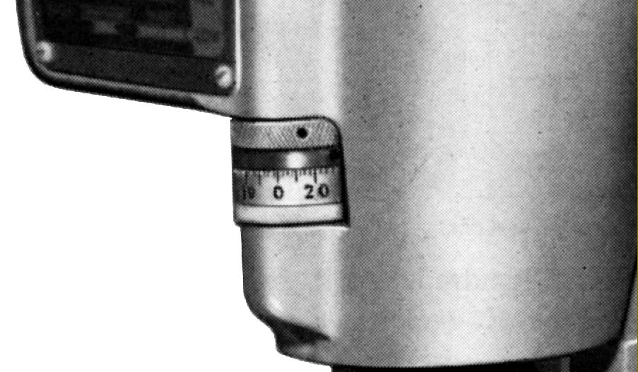
Driven by a shorter-than-normal to keep the overall height within reason, the 1-A and 1-B both had hand-feed tables as standard - though power is often found fitted as an option. From the motor a two-stage drive gave eight speeds - four by V-belt on 4-step pulleys and a high/low range through a toothed belt arranged to run over pairs of large and small pulleys. The customer was given a choice of three motor speeds: 900, 1200 or 1800 r.p.m that gave, respectively, spindle speed ranges of: 180 to 2825 r.p.m., 140 to 3800 r.p.m. or 215 to 5650 r.p.m. Early models were fitted with a 2-speed 0.75/1 h.p. motor (and possibly lacked the toothed drive) - but this this was changed at some point for a single-speed 1 h.p. unit. Although altering speeds meant the tiresome swapping of belts from one pulley to another, one advantage of this head was its very quiet running - it being far superior in this respect to either a Bridgeport or the "backgeared" head used on the Toolmaster 1-D. The 1-A was the basic model - this variant disappearing from the lists during the late 1950s - with lever-action manual down-feed only, whilst the 1-B was equipped with power down-feed - though only two rates, selected by a push/pull knob, were offered. At 0.006" per revolution, the faster feed was satisfactory but the slower, at 0.003", was insufficiently fine. Other models in the range, the 1-D and 1-E, had three feed rates, 0.0015", 0.003", 0.006", both up and down with a simple rotary-control change. The feed gearbox was lubricated by oil splash from a sump, both models had proper micrometer depth stops (the power-feed version had a clutch, arranged to slip as the drive reached the stop) and direct-fitting collets in the spindle nose. Machined at the back to accept a slotting head (simply swinging the turret around brought it into play) the ram had a travel of 14 inches (driven easily by a crank handle) with the head able to be inclined quickly and accurately through worm and wheel gearing once the four clamping bolts had been slackened.
Continued below:
|
|
|
|
|
|
|
 |
|
|
|
|
|
|
Cincinnati Toolmaster Model 1-B with power feed to the quill
Continued:
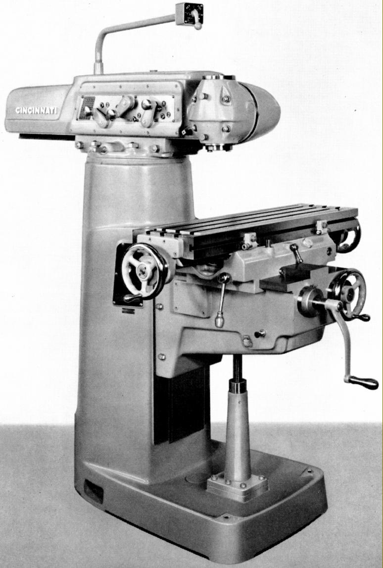
Fitted with a head having 17 inches of ram travel the 1-C was intended to be the most versatile model in the range and used the geared turret assembly offered as an accessory on other Cincinnati millers including the Dial Type, Cinedo and other general-purpose models. With a built in 2 h.p. motor and all-gear drive, this was an especially robust unit with a huge No. 40 International taper in the quill and a speed range that ran from 100 through 140, 215, 310, 490, 700, 1070 to 1530 r.p.m. Offered in standard from without quill feed (to improve rigidity) a conversion kit was available to allow the fitting of a short-travel (3-inch) spindle - though this involved the sacrifice of the No. 40 fitting and the use of a less rigid, smaller-capacity, B & S No. 7 taper. When fitted to the 1-C, the overarm was supplied complete with its vertical head mounted on a special, extended-length, double-swivel adaptor, the pair making a dedicated unit that could not be separated. This longer swivel housing was designed to allow the machine to be converted for horizontal milling, the head being rotated, to face inwards, and so provide a horizontal drive - the other end of the cutter arbor being supported in a conventional drop bracket positioned between the drive unit and column. If a non-quill feed head was required for use on the 1-B model, another version of the swivel housing was supplied.
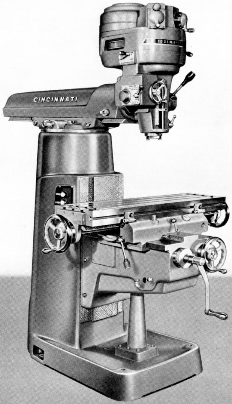
Introduced in the mid 1950s, the 1-D was an improved model and featured a much larger head with a more powerful motor (1.5 h.p. as standard but optionally, at extra cost, 2 h.p.) driving a mechanical expanding and contracting variable-speed pulley system to give a range from 85 to 3800 r.p.m. The head unit was divided into upper and lower sections: the top contained the belt drive and the lower a lathe-like backgear system (using helical gears) and (if specified at extra cost) a power-feed drive to the quill. The machine was fitted with a spindle brake as standard and the 5-inch travel quill had both rapid-action by lever and fine feed by worm-and-wheel gearing.
Continued below:
|
|
|
|
|
|
|
 |
|
|
|
|
|
|
Top-of-the-range Cincinnati Toolmaster Model H-V with geared overarm, special double-swivel bracket for the head, horizontal arbor and support bracket, a 1-D variable-speed drive head at the rear and power longitudinal and cross feed units
Continued:
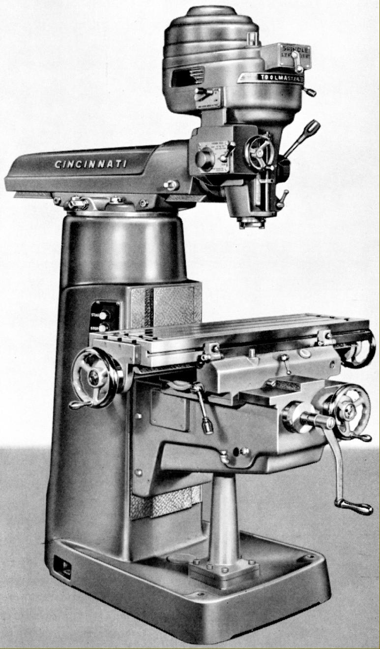
Identical to the 1-D in all respects except the head, the 1-E retained the lower section containing the reduction gearing and quill feed, but used a cheaper drive system that was, in effect, a more robust version of the all-V-belt-drive head used on earlier models.
Both the 1-D and 1-E are easily recognised by their large head, with the motor set well to the rear of the spindle line, and a rectangular rather than square switch housing on the front. Aided by the torque-enhancing backgear, spindle speeds spanned a most useful range: from 80 though 137, 234, 400, 600, 1030, 1750 to 3000 r.p.m.
Interestingly, the other model in the range, the very rare H-V (Horizontal-Vertical), was based on the 1-C and used the same all-geared head. Also fitted, on the back of the ram was a variable-speed Type 1-D head with power down-feed. So equipped, the Toolmaster became, in this ultimate form (though at some considerable cost), an even more versatile and useful machine. Speeds from the geared head could be specified as 75 to 1130 r.p.m or, optionally (and at no extra cost) from 50 to 750 r.p.m.
Until the late 1950s all versions were listed as having a 36" x 10" table with three 11/16" T-slots, hand-feed only as standard (independent power feeds to the saddle and table were optional) with a travel of sixteen inches longitudinally, ten inches laterally and seventeen inches vertically. For an extra charge a forty-two inch table could be supplied that had twenty-two inches of travel - a fitting that was eventually to be made part of the standard specification. However, when the forty-two inch table was standard, a further offer was made of a forty-eight inch table with twenty-eight inches of travel. Other table-related options were hardened and ground feed screws, a set of precision measuring equipment for longitudinal, lateral and vertical movements (and the various guides to carry the rods and DTIs); built-in optical measuring equipment and, of course, a coolant supply with the necessary electric pump and pipework. The feed-screw micrometer dials were usefully large, with well-spaced graduations, and handles were always fitted at both ends of the table. One useful fitting, common to all types, was an anti-backlash mechanism on the table-feed screw. This was not the complex unit used on the Dial Type and other general-purpose millers, but a simple arrangement where the nut was in two parts, one end being of larger diameter and threaded to accept two cap-headed screws that were used to drew it, laterally, against the feed screw. Table power feed, when specified, could be fitted to either or both longitudinal and traverse directions, with each having an identical nine rates from 0.75 to 15 inches per minute. Power was from a flange-mounted motor driving a self-contained, oil-immersed gearbox with control by the juxtaposition of two quadrant levers. Feeds were automatically disengaged by the usual dogs carried in a T-slot that ran down the length of the table's front face and proper micrometer stops - ideal for hand work - were also fitted as part of the ordinary equipment (but only on the non-power-feed versions).
All sliding surfaces were fitted with what the makers described as a headless type gib strips; these were of the ordinary tapered type, but with a socket-head screw let in flush at one end in such a way that a flange on its stem engaged with a cut-out in the strip. Adjustment could be fiddly and some effort was needed to get a good sliding fit with no play.
As a concession to heavy industrial use, and to guard against operator neglect, two separate one-shot, pull-and-release lubrication systems were fitted. One supplied oil to the saddle-to-table and saddle-to-knee ways and the longitudinal and cross feed nuts whilst the other lubricated the knee-to column ways and all the component parts of the knee-elevation mechanism - the screw and nut, support bearing and spiral-bevel gears. However, this still left the user to check seven different oil levels and attend to two
|
|
|
|
|
|
|
|
|
|
|
|
 |
|
|
|
|
|
|
Cincinnati Toolmaster Model 1-E with V-belt drive to the spindle, a speed-reducing "backgear" and the optional-extra power-feed quill
|
|
|
|
|
|
|
 |
|
|
|
|
|
|
Cincinnati Toolmaster Model 1-D with variable-speed drive to the spindle, backgear and a power-feed quill
|
|
|
|
|
|
|
 |
|
|
|
|
|
|
Cincinnati Toolmaster Model 1-C heavy-duty type with all-geared overarm. The model shown is to basic specification, without power feed to the table.
|
|
|
|
|
|
|
 |
|
|
|
|
|
|
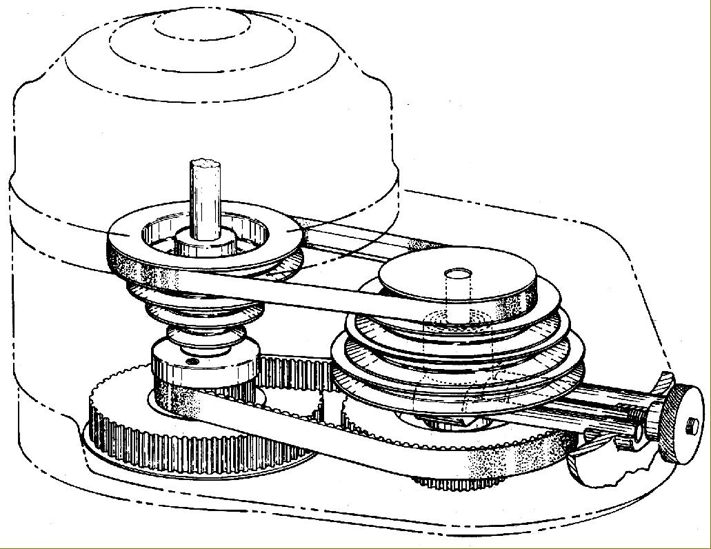
Quiet-running drive system used on the 1-A and 1-B Toolmaster with a combination of V and toothed belts.
|
|
|
|
|
|
|
 |
|
|
|
|
|
|
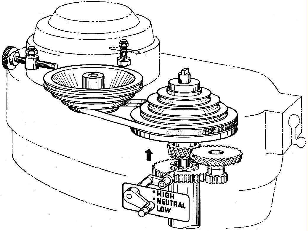
Heavy-duty, V-belt and backgeared drive used on the 1-E Toolmaster
|
|
|
|
|
|
|
 |
|
|
|
|
|
|
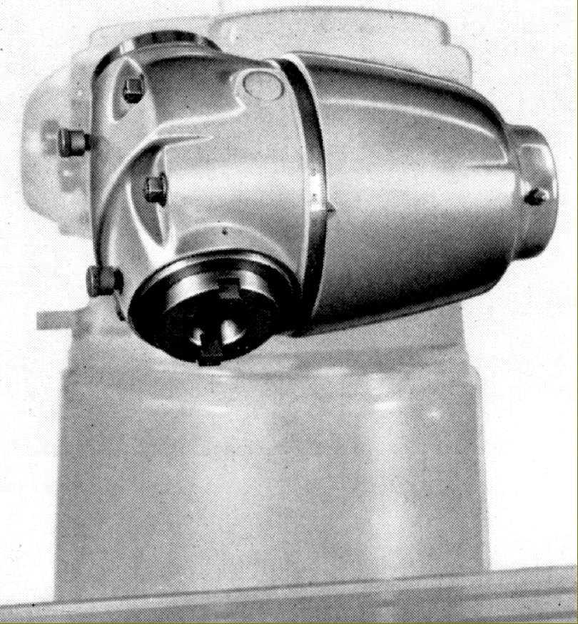
Heavy-duty No. 40 spindle vertical head fitted to the standard double-swivel adaptor
|
|
|
|
|
|
|
 |
|
|
|
|
|
|
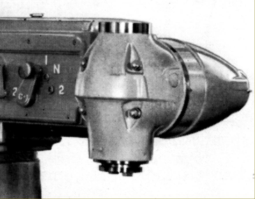
Heavy-duty No. 40 spindle head as used on the 1-C Toolmaster with an extended double-swivel housing that allowed the head to be turned so as to drive horizontally
|
|
|
|
|
|
|
 |
|
|
|
|
 |
|
|
|
|
|
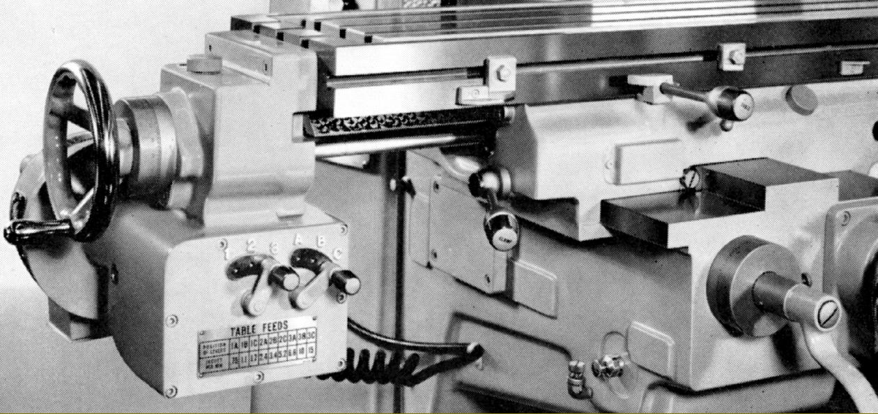
Power unit for traverse feed
|
|
|
|
|
|
|
 |
|
|
|
|
|
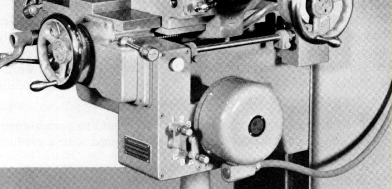
Table power-feed attachment
|
|
|
|
|
|
|
 |
|
|
|
|
|
|
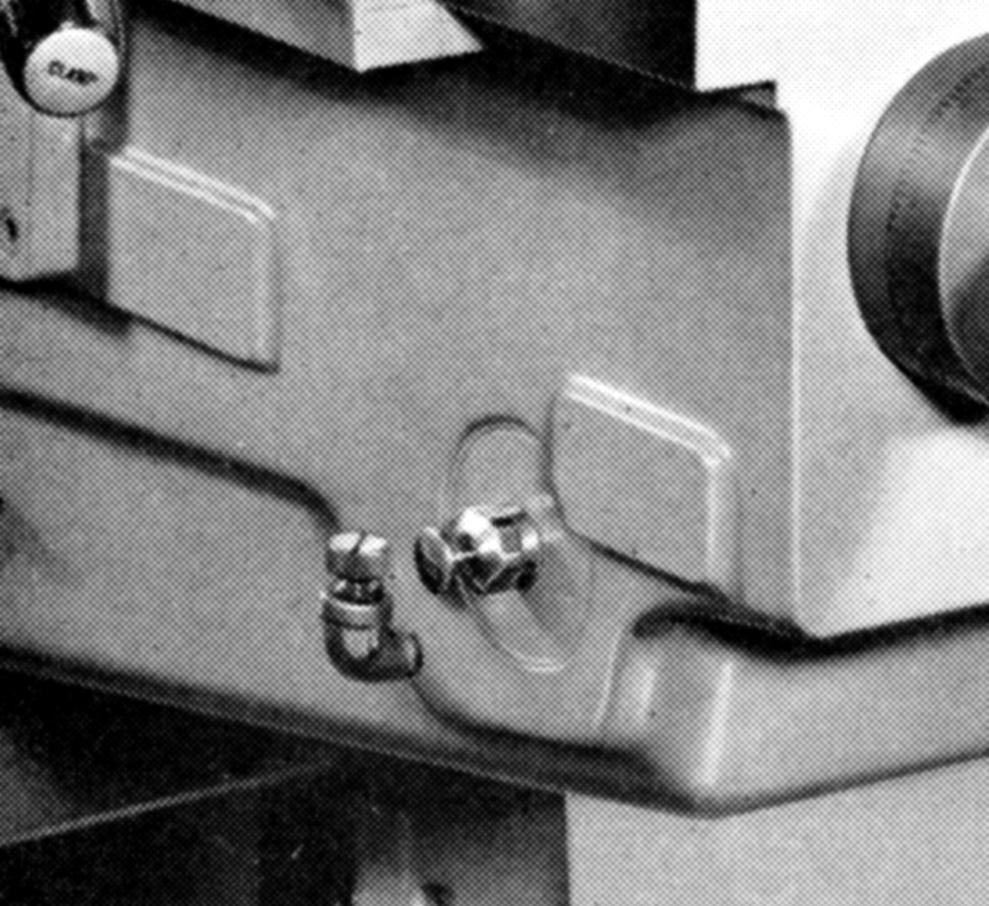
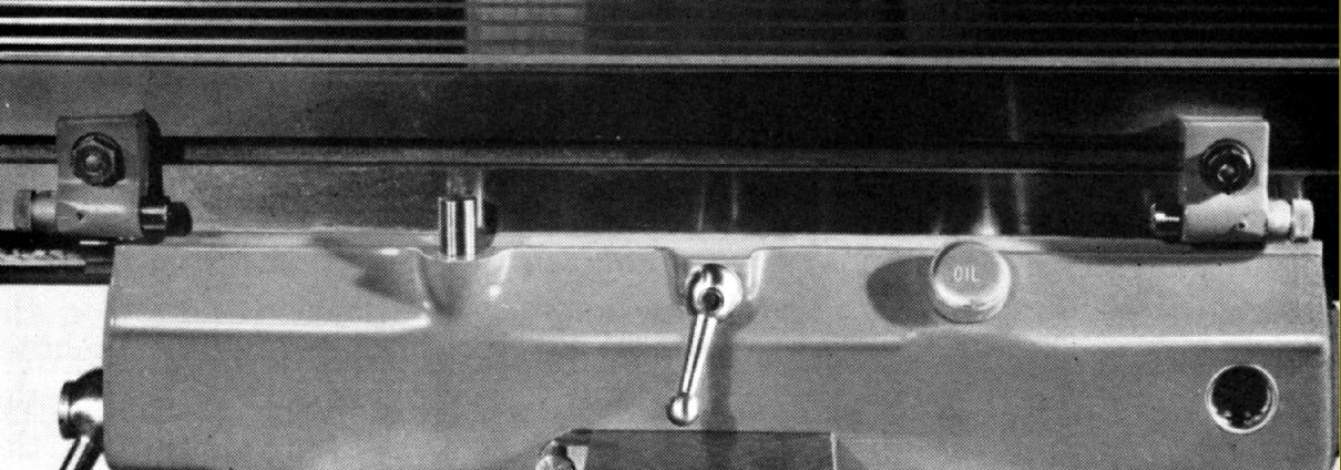
One-shot oiler for the knee-to column ways and all the component parts of the knee-elevation mechanism - the screw and nut, support bearing and spiral-bevel gears.
|
|
|
|
|
|
|
|
|
|
|
|
 |
|
|
|
|
|
|
One-shot oiler for the saddle-to-table, saddle-to-knee ways and the longitudinal and cross feed nuts
|
|
|
|
|
|
|
 |
|
|
|
|
|
|
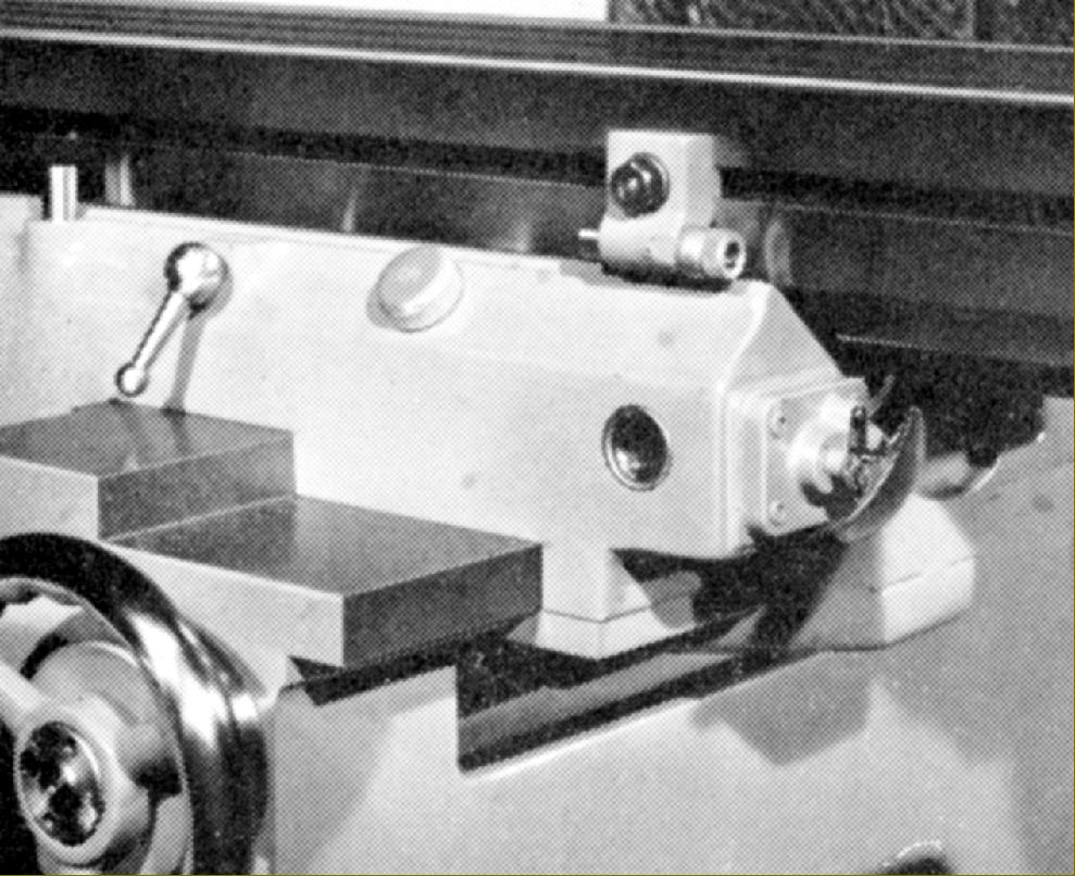
Trip dogs for the automatic disengage of the table's power-driven longitudinal feed
|
|
|
|
|
|
|
 |
|
|
|
|
|
|
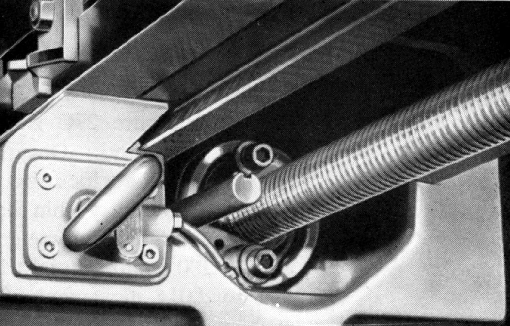
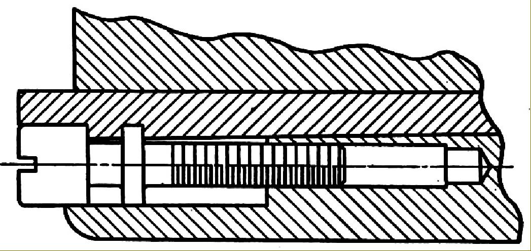
One useful fitting common to all models of Toolmaster was an anti-backlash mechanism on the table feed screw. This was not the complex unit used on the Dial Type and other general-purpose millers, but a simple arrangement where the nut was in two parts with one end of larger diameter and threaded to accept two cap-headed screws that were used to drew it laterally against the feed screw.
|
|
|
|
|
|
|
 |
|
|
|
|
|
|
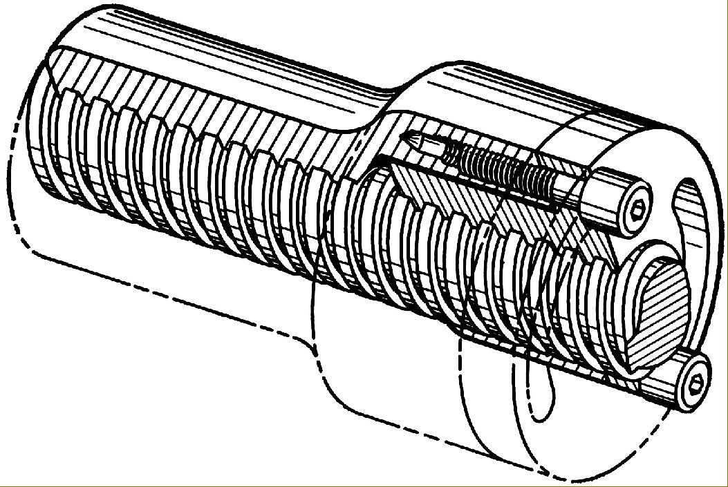
Ghosted view of the anti-backlash mechanism
|
|
|
|
|
|
|
 |
|
|
|
|
|
|
All sliding surfaces were fitted with what the makers described as a headless type gib strips; these were of the ordinary tapered type - but with a socket-head screw let in flush at one end in such a way that a flange on its stem engaged with a cut-out in the strip. Adjustment could be fiddly and some effort was needed to get a good sliding fit with no play.
|
|
|
|
|
|
|
 |
|
|
|
|
|
|
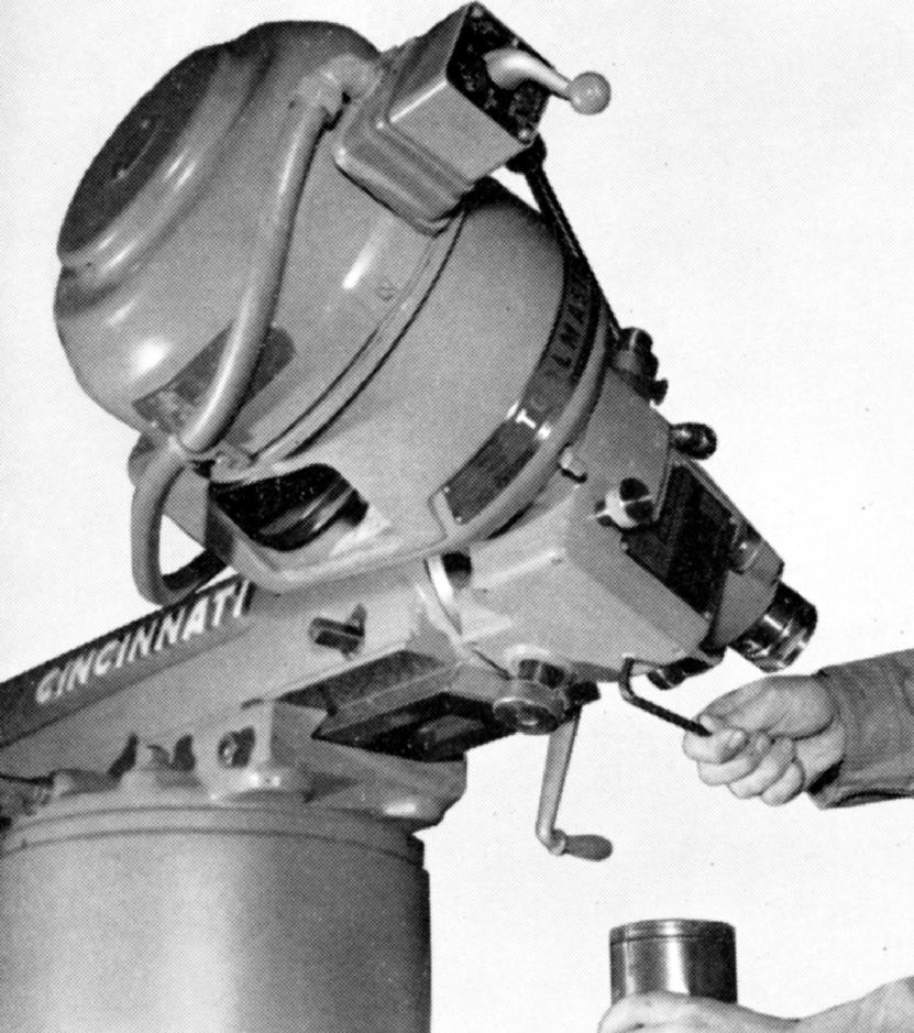
Toolmaster head being drained of oil
|
|
|
|
|
|
|
 |
|
|
|
|
|
|
|
|
|
Toolmaster slotting attachment
|
|
|
|
|
|
|
|
|
|
|
|
|
|
|
|
|