 |
|
|
|
|
|
|
|
|
|
|
|
|
|
|
|
|
|
|
|
|
|
|
|
|
|
|
|
|
|
|
|
|
|
|
|
|
|
|
|
|
|
|
|
|
|
|
|
|
|
|
|
|
|
|
|
|
|
|
|
|
|
|
|
|
|
Made from 1929 until the 1970s, the company's largest general-purpose millers were advertised during those years as the Dial Type and offered in plain horizontal, universal (with swing table) and vertical. The model was also produced in England, from 1940 to 1964, with these versions carrying serial number that ran from B4012-100 (1940) to B6401-4 (1964) - the year of manufacture being the first two digits after the B prefix. Sizes ran (eventually) from No. 1 to No. 4 as vertical machines and from No. 2 to No. 6 in the other types. In all, the customer could choose from six different versions, though these were paired as the 1 and 2, 3 and 4 and 5 and 6 to share three sizes of column - as well as a plethora of smaller parts. Although the standard range was highly adaptable, it was always possible to specify any model with a higher speed range - the ordinary speed set being referred to as Medium by the makers. The Dial Type was developed through four versions, though, as their evolution was gradual, the makers did not distinguish between them with Mk. numbers. However, to quickly identify the various ages (and to ensure the correct operation and service manuals are ordered) they will be classified as such-- in general it only being necessary to look at the control levers and position of the speed and feed dials. On Mk. 1 models, from the 1930s until the early 1940s, the control handles were solid, all-metal tapered types. Mk. 2 machines, from around 1942, economised with plain bar handles tipped with plastic knobs (except for the vertical head capstan handle) - and all machines up to that time (Mk. 1 and Mk. 2 used two dials on the left-hand face of the main column, one for spindle speeds and the other for table-feed rates. However, on the Mk. 1 the dials were mounted on a plain rectangular background on the Mk. 2 on a triangular surface complete with a chart showing the relationship between speeds, feeds and cutter diameter. From the late-1940s onwards several significant alterations were made with the introduction of the Mk. 3 - the main outward identifying feature of which was a single, large, combined speed-and-feed dial on the side of the column to replace the two individual ones and a flat face to the end of the overarm. This model ran virtually unchanged until the late 1950s when the Mk. 4 was introduced - though this was seen first a couple of years earlier as the new and larger No. 5 and No. 6 types. The Mk. 4 was particularly distinctive in appearance with one dial for speeds on the left-hand face of the main column and a very large feed dial fixed to the left-hand face of the knee. At the same time the control system was altered to reduce the number of levers and incorporate electrical push-button-actuation. The final version was listed by the makers as the Cinedo, not the Dial Type, and was a considerably re-engineered machine - a true Mk. 5 in many respects. It had modern, angular lines, a spindle-speed dial in the usual place, on the left-hand face of the column, but with the feeds dial re-positioned to the front face of the knee - another immediate point for easy identification (though easily confused with the late-model MI, a model that shared an identical fitting). As, by this time, conventional millers were little used for production, the quick changing of feeds and speeds was no longer of paramount importance and these final versions saved money by using a simpler and cheaper form of control with direct dialling by the operator.
To compliment the standard Dial Type range Cincinnati always offered High Power and Dual Power versions. Although of very similar appearance to the ordinary models these had the ability to mount heavier jobs through the use of more powerful motors for both spindle and feed drives, a slightly slower top speed (down by 200 r.p.m.) and larger tables - though with exactly the same travel.
Continued below:
|
|
|
|
|
|
|
|
 |
|
|
|
|
|
|
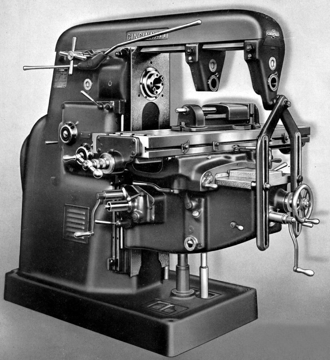
Mk. 1 1930s Dial Type No. 3 Plain Horizontal. Note the solid metal handwheels and levers, the bevelled face at the front of the main column and the long extensions on the left-hand face of the knee where the crank handles fitted. Further simple recognition points for early types include the overarm brace with one bolt on the drop bracket, the feed and speed dials mounted on a plain rectangular surface and the name Cincinnati ser in a recessed panel.
|
|
|
|
|
|
|
|
|
Continued:
Controls
All Dial Type millers were carefully designed to get the most out of an operator and had complete duplication of all controls at front and rear on horizontal models - though only rear control of longitudinal feeds on the vertical. Being large, manually operated machines, it was often necessary for the machinist to stand behind the table to see the job clearly and having to walk backwards and forwards, from front to rear, alternatively operating controls and inspecting work not only wasted a huge amount of time per shift but was dangerous and, on some jobs, impossible. Dual controls therefore not only helped to make work easier - they also reduced mistakes and errors in operation. For example, when changing the cut direction from the front the operator had to remember to reverse this when viewed from behind - easy to do at the start of a shift, but not so simple after eight hours on your feet, or if distracted by that delicious Mavis Ramsbottom from Accounts picking her way delicately across the shop floor. On all models (except the later "push-button" types) levers were used that worked with elegant simplicity and encouraged the use of exactly the right settings for each job. A single lever sufficed to alter the spindle speed and the rate of table feed and, as independent motors were used for each, it was unnecessary (as on so many competing machines) to compensate for changes in the spindle's direction of rotation. To select the direction of table travel separate levers were used that had a neural position and worked in a common-sense, directional way. For example, lifting a lever caused the knee to rise, moving another to the left made the table shift in that direction, etc. When the feeds and speeds lever was moved the appropriate indicator dial clicked round, pausing for a moment at each index mark and then, as the lever was released at the chosen setting, the gears (for speeds or feeds) were automatically engaged by hydraulic power. As synchromesh cones were used to ensure a smooth change, the controls could be operated without having to stop the motors and a change from the slowest to highest speed took only a few seconds. Piece-work employees must have been in seventh-heaven.
Automatic Backlash Eliminator
One useful attachment, that required building in on the production line, was an automatic backlash eliminator for the longitudinal feed screw. Used on many Cincinnati models from the mid 1940s onwards, the device was intended for use during climb milling. The latter is a process where, instead of the workpiece being pushed against the rotation of the cutter (and so any backlash between feedscrew and nut automatically eliminated) the work is fed into the cutter in the opposite direction - producing a tendency for the table to be violently "grabbed" forwards. During automatic table-cycle processes, where a cut was required in both directions, climb milling was, of course, necessary and the Backlash Eliminator an essential fitting. The mechanism was contained in a single housing and comprised two separate feed nuts, each machined on its outside with teeth that meshed with a rack. The racks were arranged to sit at each side of a spur gear that, when rotated, moved one rack forwards and the other backwards - so forcing the nuts to rotate slightly in opposite directions. As the nuts turned, the effect was to remove backlash by seating each firmly against opposite sides of the feedscrew thread and so "load up" the assembly. With the unit engaged climb milling became as easy as conventional - and, in a production process, could double the effective work rate of the machine..
Spindle speeds and feeds
For many years the medium speed No. 3 and No. 4 models (the most popular sizes) in all types, horizontal and vertical, had sixteen speeds spanning 18 to 450 r.p.m. whilst the high-speed versions had a more useful set of twenty-one, from 18 to 1300 r.p.m. Longitudinal and cross feed rates were also different, the standard models normally having sixteen of each from 5/8" to 20" per minute and the high-speed twenty-four from 5/16" to 60". However, if required, the medium-speed version could be fitted (at no extra cost) with lower or high rates of feed: the former spanning either ¼" (or 5/16") to 10" and the latter ¾" (or 1") to 30". The No. 2 version was built to a different specification with the medium-speed model having 16 spindle speeds from 20 to 500 r.p.m. and the high-speed version twenty-one from 20 to 1500 r.p.m. Both machines had an identical range of sixteen rates of table feed from ½" to 20" - and the option of (fixed, factory-installed) faster and slower rates as well. All table movements were fitted with "rapids" - longitudinally and across at 150" per minute and vertically at 80" - giving a very quick return to the start of a job and reducing "cutting air" time. To stop and start the spindle a powerful combined multi-disc clutch and brake was used operated by hydraulics and controlled by a long handle whose position was easily adjusted to a comfortable working position. On early models two clutch levers were used, one pointing forwards, the other to the rear.
Whilst vertical models used the same tables and associated controls as the horizontal, they were usually delivered with a head having not just ordinary power down-feed, but rapids as well (the latter fitting known as lateral feed by the makers).
Lubrication
Correct lubrication is vital on any industrial machine - but the more often this is left to the whim of the operator, the greater is the likelihood that it will be neglected. Dial Type millers had a largely automatic oiling system with reservoirs that were easily filled and glass-fronted flow and level widows. The knee and column were both equipped with powered plunger pumps to lubricate the internal mechanisms, and knee to column ways, by pressure and splash. One interesting touch was effort made with the heavily stressed, one-piece, nitrided-steel vertical screw: this was supported on taper roller bearings, ran through an aluminium-bronze nut and was completely enclosed in a separate bath of EP oil - a reservoir positioned to one side (and level with the screw's top) feeding oil down a pipe to fill a surrounding housing. Table and saddle ways - and the table feed-screw end bearings - were lubricated by a one-shot pressure system, driven by an operator-actuated pump, mounted on the front left of the saddle on horizontal millers and to the right on vertical.
Continued below:
|
|
|
|
|
|
|
|
 |
|
|
|
|
|
|
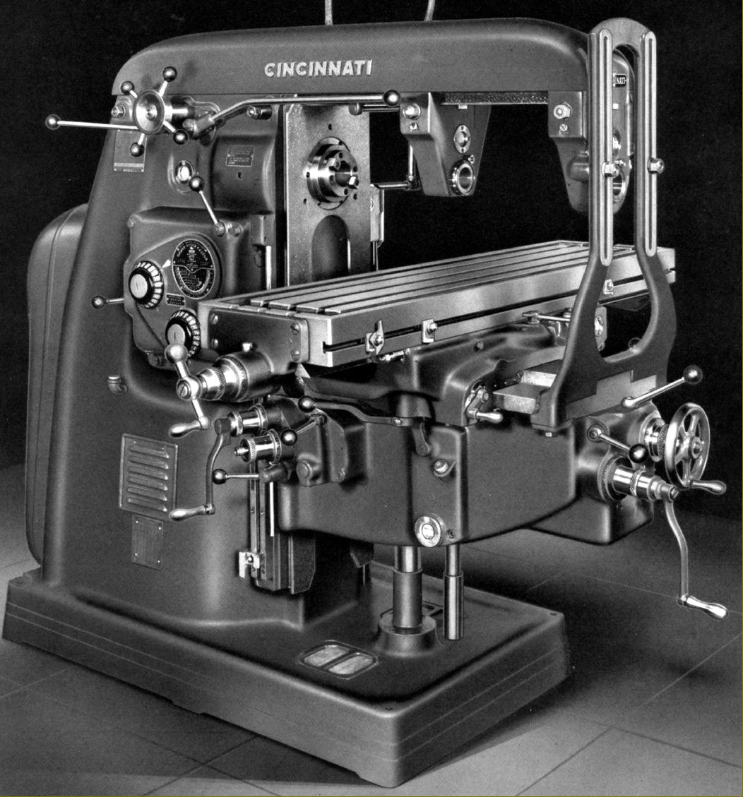
Mk. 2 early 1940s Dial Type No. 3 Plain Horizontal miller. Recognition points include control handles tipped with balls (a change introduced in the early 1940s) an overarm brace with a two-bolt fixing to the drop bracket, speeds and feeds dials on a triangular background complete with feeds and speeds chart and, on the left-hand face of the knee, shorter sockets for the two cranks handles.
|
|
|
|
|
|
|
|
|
Continued:
Motors
Varying considerably in output according to the size of the machine, the motor was mounted on an adjustable plate within the base of the main column. On the very earliest machines, a choice was offered between drive by an oil-lubricated "silent chain" and four V-belts; in the event the latter proved by far the more popular and the chain option quickly disappeared from the catalogues.
Accessories
In addition to the expected arbors and cutters, a very wide range of extras was offered - though the full range was not always available in every decade and contracted sharply during the 1960s. Included were seven different types of vertical head and attachments and accessories for: powered slotting; dividing and indexing together with an enclosed gear-driving attachment and suitable raiser blocks to increase capacity; rack cutting and indexing, gear cutting, power and hand-driven circular milling; powered universal spiral milling; plain, swivel and tool maker's vices; quick-change tooling adaptors (later made standard); a cap-type intermediate arbor support for mounting between cutters; cam milling with hand or power feed; keyway milling; a special "wide-range" dividing head (that could also be applied to a stand unit) that gave divisions from 2 to 400,000 and any angle at intervals of six seconds without the need for changewheels or other than the standard indexing plate; a range of factory-fitted precision measuring equipment of the traditional type to hold length-rods and slip gauges; a right-angle drive attachment with a forward pointing handwheel that drove the table longitudinally to allow the operator to closely follow the contour of a die; an electric coolant pump (in place of the standard gear-driven type) with the necessary piping and, finally, for the vertical head, power and rapid feeds in both directions and a four-position turret stop.
Late-model Dial Type milling machines
Before the introduction of the heavily revised versions (with separate column and knee dials) the sizes 2, 3, 4 were fitted with electrical push-button control of spindle start, stop and speed selection - and so removed the need for the traditional clutch lever or starting handle as Cincinnati termed it. The push buttons were arranged along the front edge of the saddle and duplicated on the left-hand side of the column - with a further set of controls on the right-hand side to start and stop the spindle, switch the coolant on and off and electrically isolate the machine.
Manufactured from the mid 1950s onwards - but at first only as the new and larger No. 5 and No. 6 machines and as High Power and Dual Power versions of the others - the last models of the Dial Type series were heavily modified mechanically, with an improved specification - and hence the standard (lower-speed) model was dropped. The High Power and Dual Power models had twenty-four spindle speeds (in a 100 to 1 ratio) spanning 16 to 1600 r.p.m on the No. 3 and No. 4 models and 14 to 1400 r.p.m. for the No. 5 and No. 6. Ordinary types were also improved and equipped much as the former High-Speed models with 16 speeds from 16 to 1600 r.p.m. (4 r.p.m. slower and 300 r.p.m. faster than before) and an increase in the number of feeds from 24 to 32 with a range that spanned from 3/8-inch to 90-inches of travel per minute. However, not all machines were equipped as per the catalogue specification and ordinary models of this era have also been found with twenty-one speeds spanning 20 to 1500 r.p.m on the No. 2 and 18 to 1300 r.p.m on the No. 3 and No. 4. With these improvements the Dial Types were now all capable of tackling not only a wider range of jobs, but also at faster rates of metal removal.
In 1959, after the new design of knee and column spread to the all types Cincinnati changed the Model numbering to one that (in the writer's opinion) had little merit. In contrast to the former very simple designations the revised set listed the machines as the Model LL and attempted to categorise them by specification using two and three-digit codes. For example, the No. 3 became the 315-15 - where the first digit indicated the table length (3 for 34 inches, 4 for 44 inches, etc.), the second pair the spindle-drive motor horsepower (15 for 15 h.p.) and the last two the table width (15 for 15 inches). The new range comprised: 315-15, 415-15, 420-16 and 520-16; in other words, respectively, the Models 2, 3, 4 and 5. In compass with these revisions the High Power models were re-listed in an identical manner the Model ELA with sizes of: 520-20, 540-20, 620-20 and 640-20.
Automatic Table Cycle
A new option, introduced in the mid 1950s on most Cincinnati plain horizontal and vertical models (but not the universal) was automatic table cycle control: this enabled an operator to set up, using specially-shaped trip dogs in a just single T-slot on the table's front face, a sequence of simple but fully or semi-automatic operations that included all aspects of table control including movement direction, feeds and rapid traverses. When fitted with cycle control the individual levers used to operate the table feeds were abandoned and replaced by a single-lever jockey control with "stop" at 5 o'clock, rapids selected left and right at, respectively, 10 o'clock and 2 o'clock and feeds similarly positioned at 8 o'clock and 4 o'clock.
Three additional controls could be added to the table cycle system, all built into the machine when new: Automatic Spindle Stop, Live Rapid Traverse and Automatic Knee Retraction. Whilst the Automatic Spindle Stop was just a simple (factory-installed) option to extend the usefulness of the automatic table cycle, Live Rapid Traverse was a more complex mechanism that provided an over-riding action built into the rapid-traverse mechanism. This, once selected, allowed the operator to set the position of the rapid feed trip dogs quickly and accurately by first mounting them in approximately the right place, starting an automatic cycle and then, when the cutting cycle engaged, using the rapid traverse lever to jog the workpiece close to the cutter. At this point the sequence was stopped, the dog set snugly against the cycle control lever and locked in place. The Automatic Knee Retraction system ensured complete safety during auto-cycle work by retracting the knee by 5/8" as the 'rapids' operated and returning it to the previous position immediately afterwards.
Fitted as standard was an Arbor-Loc spindle nose that allowed a speedy change of tools to be made whilst offering just as much rigidity as before. The Arbor-Loc also largely eliminated the need to use arbor draw bolts, a boon on vertical heads, where safety was thus greatly enhanced.
In the early 1960s a different Dial Type, the ELR, was introduced alongside the established models. Available as the 207-12 and 307-12 these had, as standard, controls at the front only (rear controls were extra) and reverted to simple lever instead of push-button operation. Available in the usual horizontal, universal and vertical types, the model can be instantly recognised if fitted with rear feeds - the sockets for the two detachable crank-handle being reversed in comparison with the older machines such that the one nearer the front was set higher than the other. .
|
|
|
|
|
|
|
|
 |
|
|
|
|
|
|
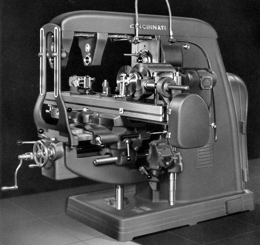
Mk. 2 early 1940s Dial Type No. 3 Universal Horizontal miller (with swing table). This model is shown fitted with the powered spiral milling attachment
|
|
|
|
|
|
|
|
|
|
|
|
|
|
 |
|
|
|
|
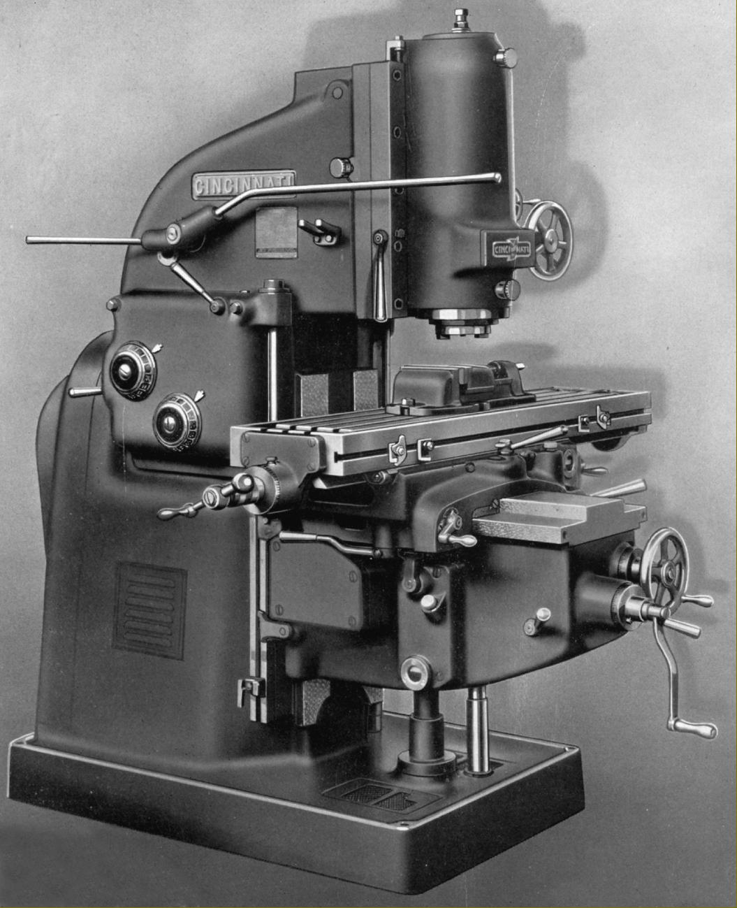
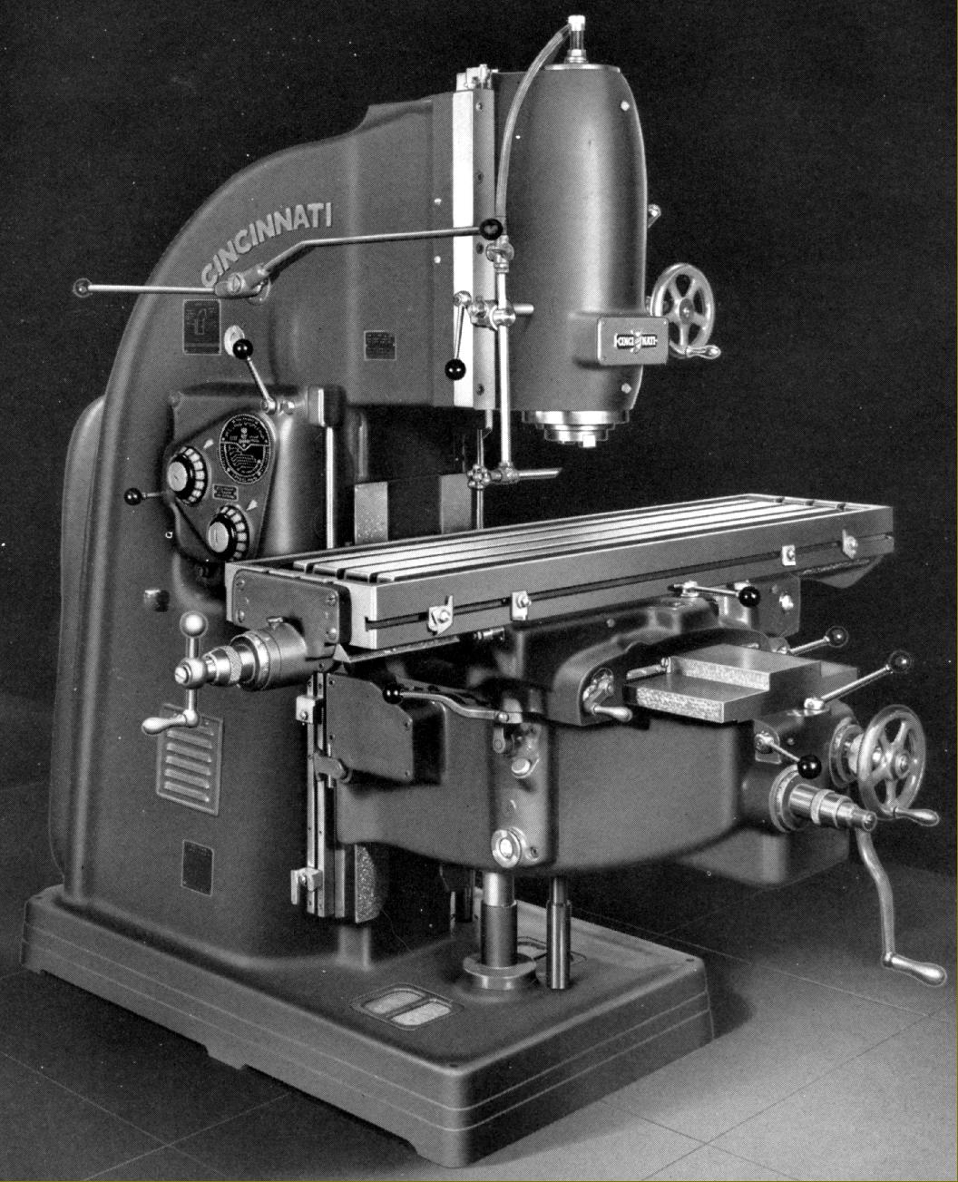
Mk. 1 Dial Type No. 3 Vertical Miller from the 1930s
|
|
|
|
|
|
|
|
 |
|
|
|
|
|
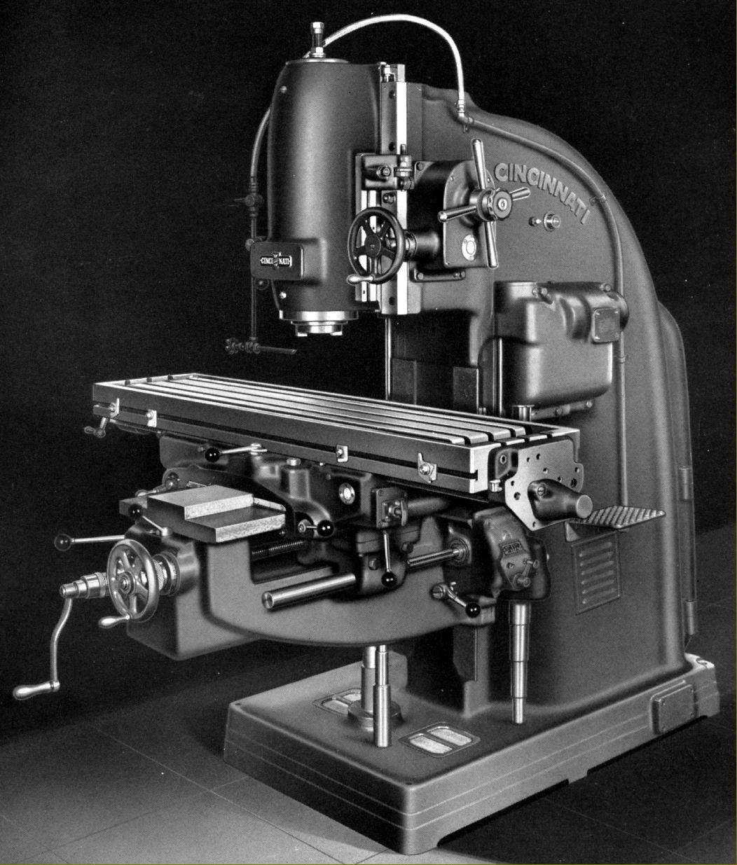
The much-modified Mk. 2 Vertical Dial Type from the early 1940
|
|
|
|
|
|
|
|
 |
|
|
|
|
|
|
Mk. 2 early 1940s onwards No. 3 Dial Type Vertical to standard specification
|
|
|
|
|
|
|
|
 |
|
|
|
|
|
|
|
|
|
Mk. 1 Dial Type vertical with standard head as manufactured during the 1930s
|
|
|
|
|
|
|
|
|
|
|
|
|
|
|
|
|
|