|
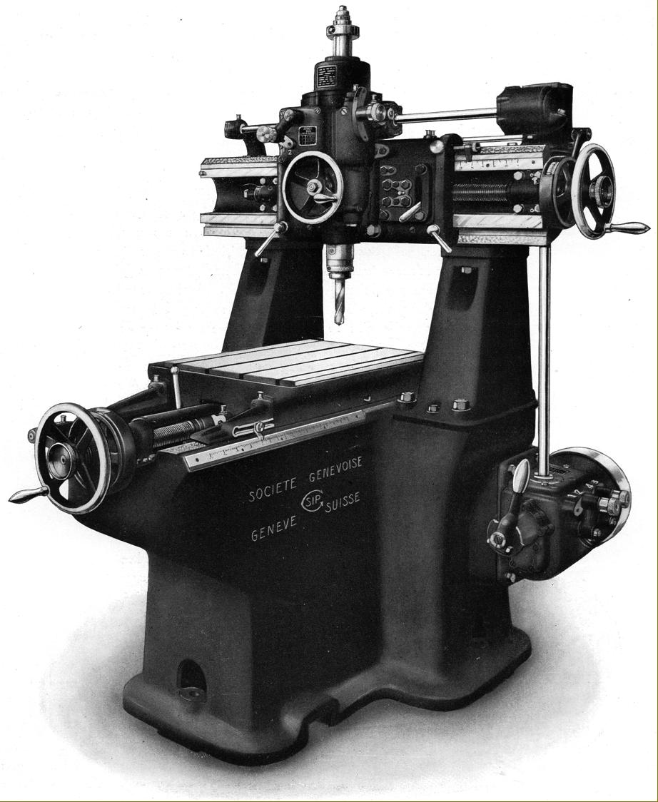
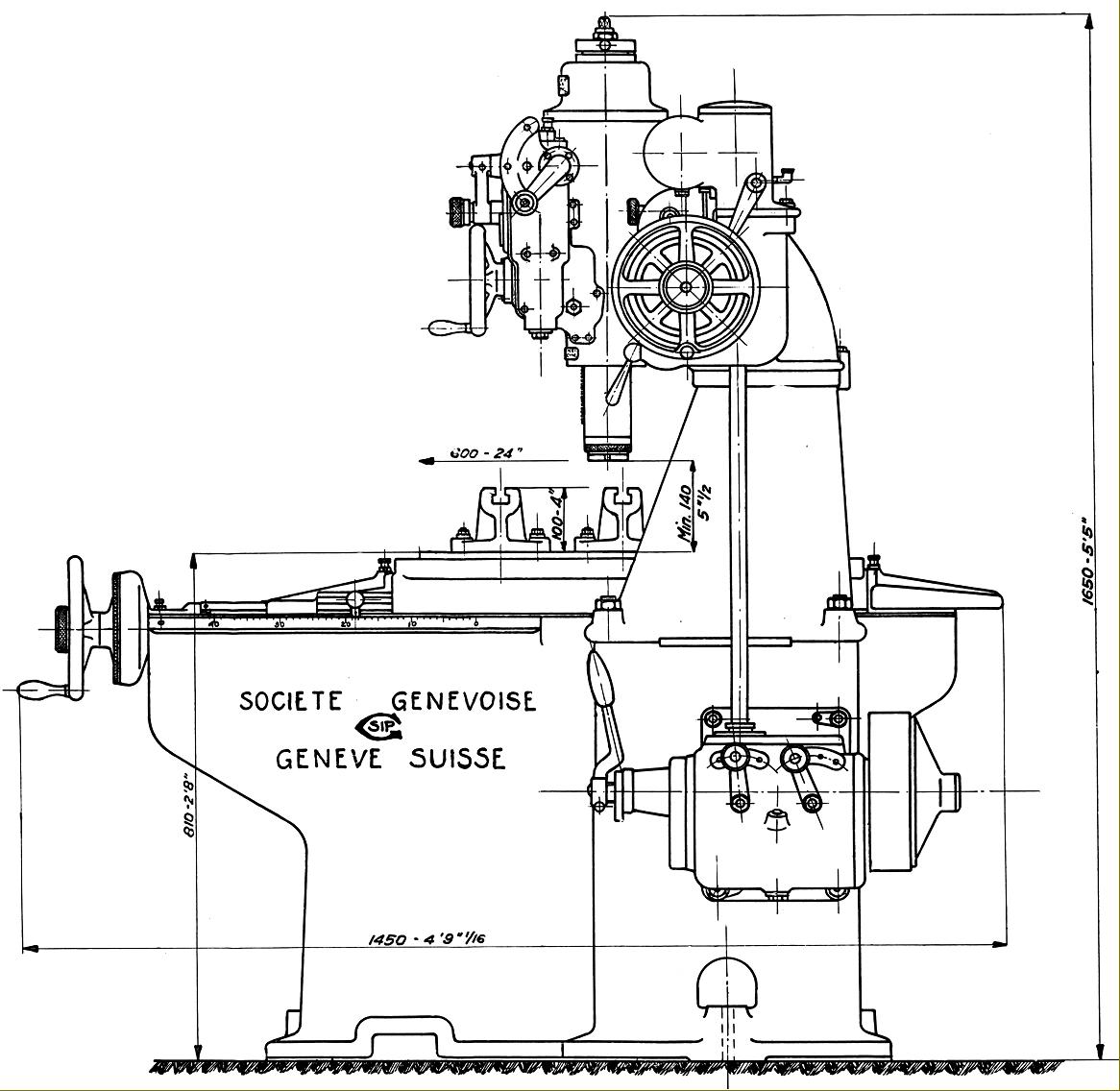
Home Machine Tool Archive Machine-tools Sale & Wanted No. 2C and No. 3 Société Genevoise d'Instruments de Physique Operation & Maintenance Manuals are available for most SIP Jig Borers SIP Home Hydroptic 6A & 7A Jig Borer 1-H Jig Borer 2P Jig Borer 3K Jig Borer 4G Jig Borer 5E Jig Borer 8P Accessories Jig Borers 1920s No. 2C and No. 3 Tooling Cabinet According to a book published in 1954 by Société Genevoise d'Instruments de Physique "As Ninety Years Went By, 1862-1952", the Model MP4 was the first industrial purpose machine built by SIP in 1921, and the first of its kind to be able to precisely locate and bore a hole. This was superseded, in 1923, by the MP5, a slightly larger machine - however, the smallest and cheapest model in Company's twin-column range of the early 1920s was the SIP No. 3, a jig borer intended as both an economical purchase for smaller machine and tool-making shops and for use in manufacturing plants. As a lighter model its work capacity was somewhat limited, it being able to drill a 1-inch (25 mm) hole and bore up to 4-inches (100 mm) in diameter - both in hard steel - and drill a 1.5-inch hole in cast iron. However, despite the lower price and specification, accuracy was not compromised, the makers guaranteeing that the maximum error in distances between the axes of bored holes would not exceed 0.0006" (0.015 mm), that holes bored and finished with a fine cut would be cylindrical and true to within 0.0004" (0.01 mm) and the accuracy of displacement of table and cross slide would be 0.0002" (0.005 mm). |
|
|

|
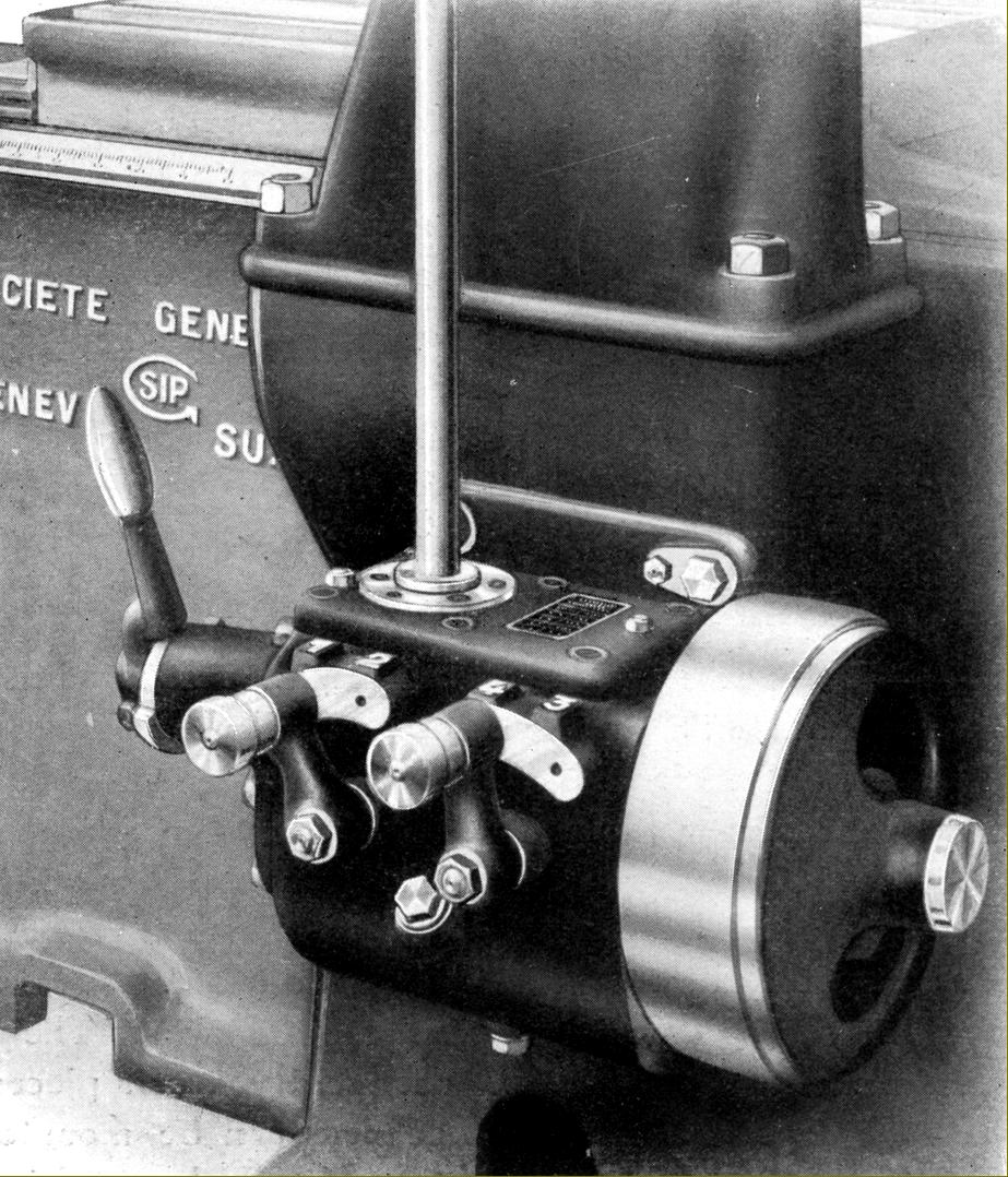
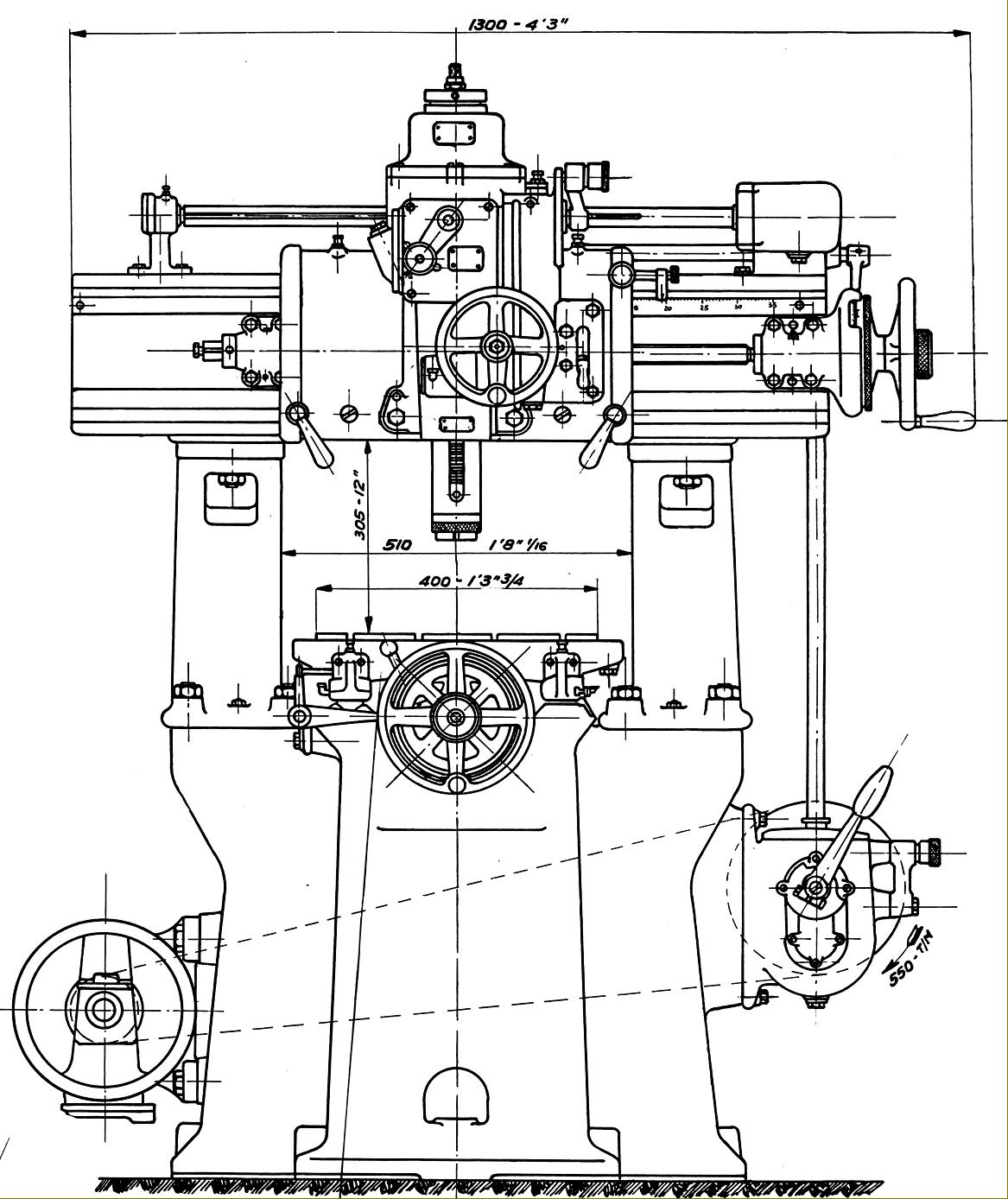
SIP No. 2C Jig Borer with (like the modern 2P) a motor mounted at the rear of the head. Little is known about this model save that the arrangement of the table and its ways was unusual. With the head fixed and unable to be moved fore and aft, the table was arranged to sit on a casting carried on two slightly elevated wings formed as part of the main body casting and running at each side of the upper column section that carried the head. |
|
|
|
|
|
|
|
|
|
Home Machine Tool Archive Machine-tools Sale & Wanted No. 2C and No. 3 Société Genevoise d'Instruments de Physique Operation & Maintenance Manuals are available for most SIP Jig Borers SIP Home Hydroptic 6A & 7A Jig Borer 1-H Jig Borer 2P Jig Borer 3K Jig Borer 4G Jig Borer 5E Jig Borer 8P Accessories Jig Borers 1920s No. 2C and No. 3 Tooling Cabinet |
||