|
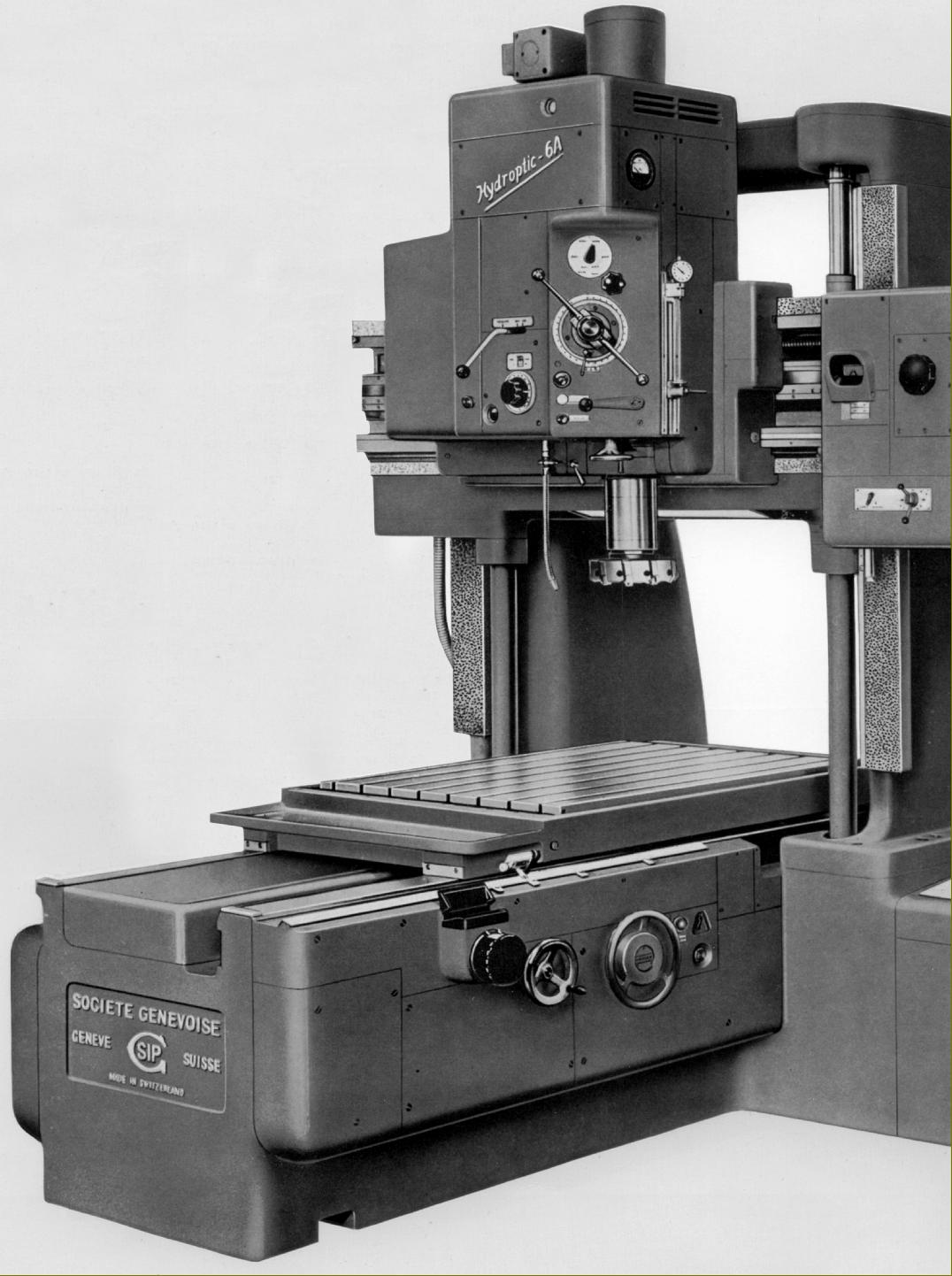
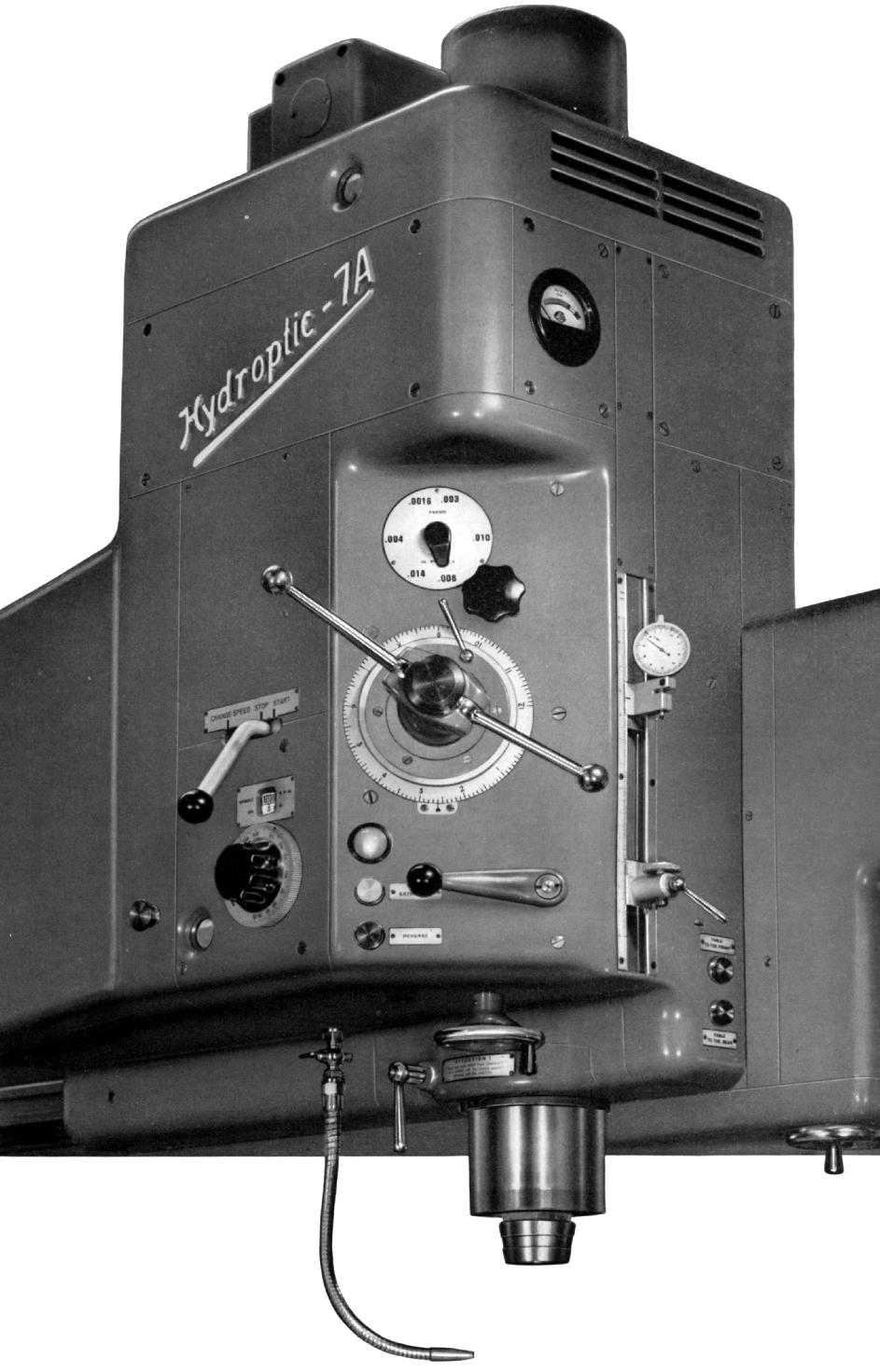
Introduced in 1934, the heavily built and weighty Hydroptic range was designed for use both as a precision production milling machine and a jig borer. By the late 1950s this popular model had developed from the earlier No. 6 to include the improved 6A (with a more robust, longer-travel spindle and a more powerful motor) and the 7A - an almost identical machine to the 6A but with increases to the table and head travels and a greater table load-bearing capacity. Also offered was the 8P, a development of the 1930s 6B, with both vertical and horizontal heads and intended, as the suffix indicated, solely for production purposes.
In developing the 6A and 7A, SIP were working towards ever-greater automation and offered the machines in three forms: for hand operation, with the DIR-coordinate repeating device or with an early form of SIP numerical (CNC) control, the latter introduced in the late months of 1960. Both the 6A and 7A were rather heaver than the immediately preceding models, some 800 kg in the former case and 1,400 kg in the latter (total weights being 9,400 kg and 14,400 kg respectively). Instead of built-in main electrical controls, in order to make installation easier, these were held in a separate cabinet supplied with 6 metres of cabling, enabling it to be placed anywhere convenient. However, the operator's controls - on and off switches, coolant pump and optical projection screens, etc. were machine-mounted immediately below the right-hand side column.
Centred around two main elements, the greater automation built into the DIR models involved:
a) an arrangement for the pre-setting and subsequent repetition of up to forty spindle-head and table co-ordinate positions - with more than forty if some were on the same axis and up to 1600 with one set using two memory drums. As the readings were displayed on the illuminated screens in the usual way, the operator could verify them just as easily as when setting them up for the first time
b) automation of the of the table and cross head - with both started automatically by pressing a button. The sequence initiated was: automatic unclamping of the worktable and head, automatic starting and stop followed by automatic re-clamping of the moving elements (of course, this was a system essential for the incorporation of numerical control, and was built-in in advance of that specification becoming available). The clamps were all servo-activated and of the powerful hydro-electric type with an advantage of the system being the consistent pressure given by the clamps resulting in minimal deflection of the main castings. These improvements were even incorporated into the hand-operated models, with the clamping activated by separate electrical switches Other more mundane improvements were also made: the hydraulic and coolant tanks were increased in capacity from 25 to 40 litres and 20 to 70 litres respectively (the extra volume helped to keep the fluid cool when the machine was working hard). Controls for selectors, record and repeat buttons etc., formerly positioned on top of the consol, were shifted to a more convenient location on the right-hand end of the cross rail.
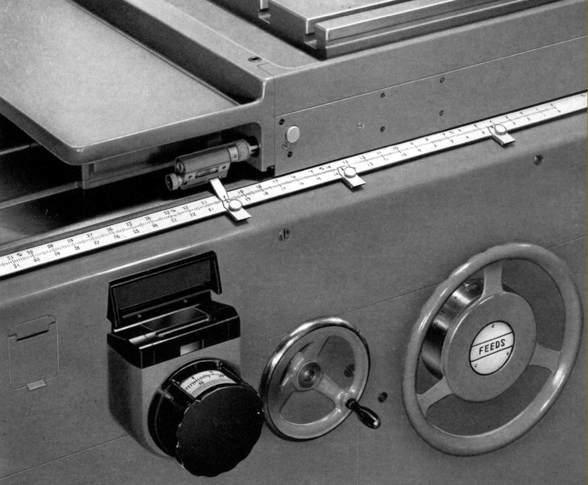
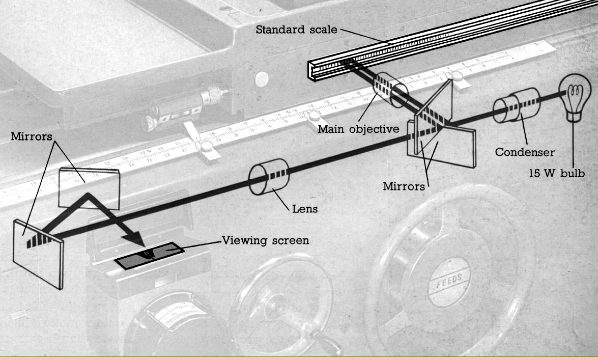
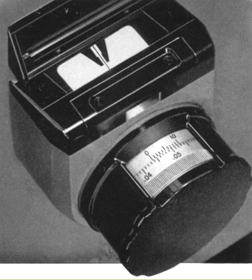
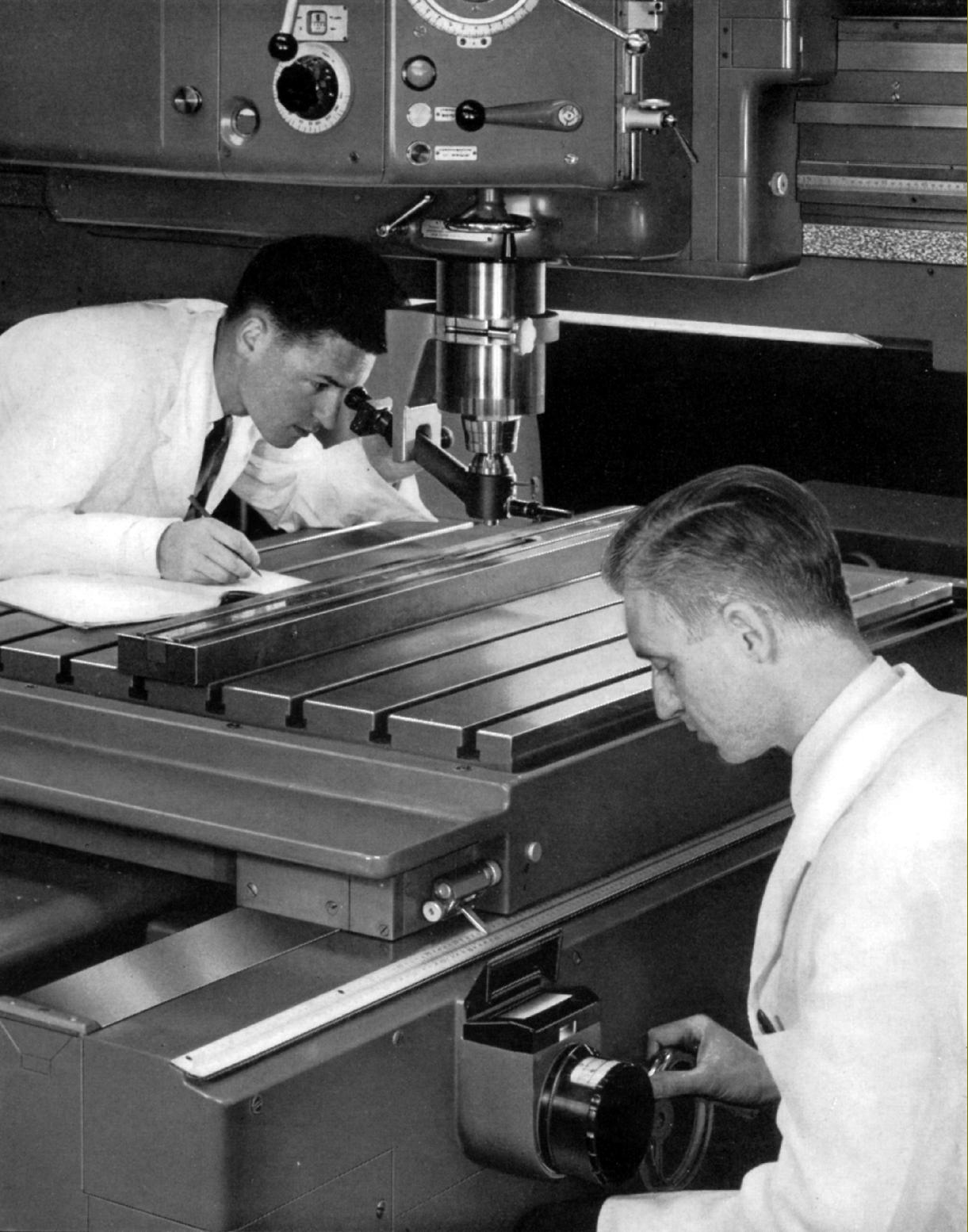
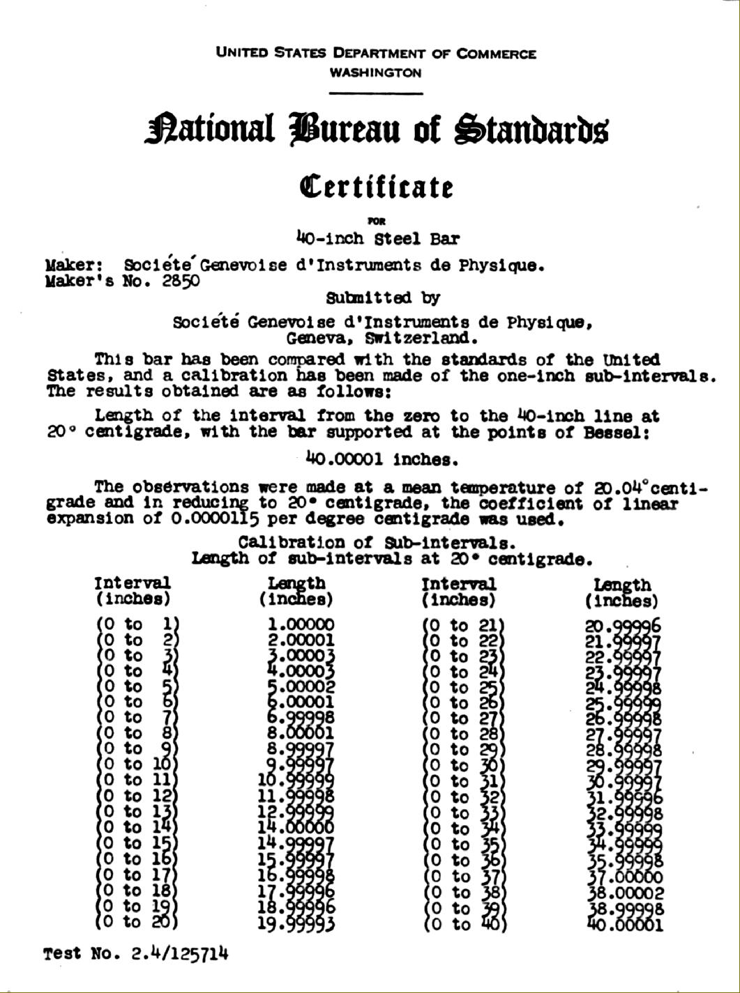
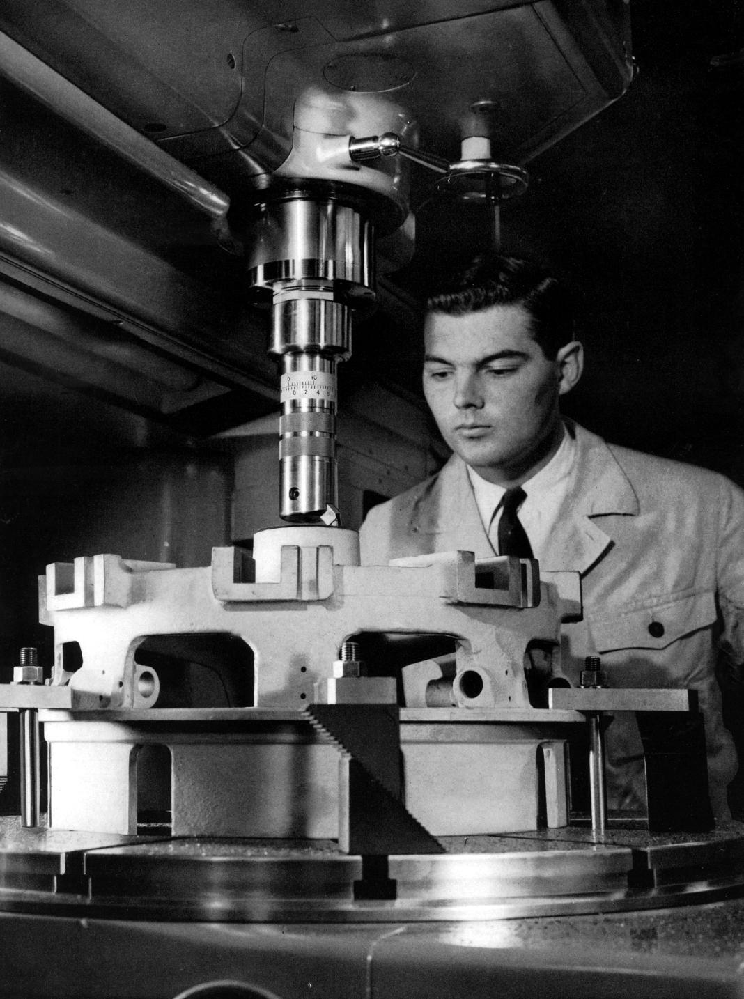
Hydroptic machines were not fitted with conventional table-drive feed-screws, instead (as the model name suggests) they used a smooth-moving, very precise hydraulic system. Thus, lacking any means of determining table travel by reference to a rotating screw and micrometer dial, they were fitted with same system used on the much smaller No. 1-H and 2P models - highly accurate standard scales of the type used to calibrate other measuring equipment in national testing organisations. The scale graduations were illuminated, magnified and projected onto a glare and parallax-free reading screen. This easy-to-use, absolutely reliable arrangement (it was entirely optical with no wearing parts) allowed readings to be taken down to 0.0001" (0.001 mm) - an astounding degree of precision for such large machines - with Société Genevoise d'Instruments de Physique also guaranteeing an accuracy for all displacements of work-table and spindle head of 0.00015" (0.003 mm) on the 6A and 0.0002" (0.005 mm) on the 7A. Of course, with the direct use of precision scales it was no longer necessary to include the automatic mechanical correction device of the type seen on the less-expensive screw-driven models.
Of identical mechanical design, and with the same motor size, spindle speeds and feed rates, the 6A and 7A differed only in their physical size, table and cross-head travels and load-carrying capability.
6A specification:
Table 43.25" x 33" (1100 x 842 mm)
Table travel 40" (1000 mm)
Head-saddle transverse travel 28" (700 mm)
Head-saddle elevation range (on the uprights) 31.25" (XX mm)
Maximum free space under the cross-rail 37.5" (955 mm)
Distance between table surface and spindle nose 39.25" (1000 mm)
Minimum distance between retracted spindle end and table surface 8" (200 mm)
Maximum load on table 2200 lbs (1000 kg)
7A - specification (see below for notes on the 8P and its differences):
Table 61.75" x 40" (1570 x 1024 mm)
Table travel 50" (1400 mm)
Head-saddle transverse travel 40" (1000 mm)
Head-saddle elevation range (on the uprights) 35.625" (XX mm)
Maximum free space under the cross-rail 48" (1220 mm)
Distance between table surface and spindle nose 50" (1265 mm)
Minimum distance between retracted spindle end and table surface 14.625" (365 mm)
Maximum load on table 4400 lbs (2000 kg)
Table feed rates - stepless within their range - could be set as high as 20" (50 mm) per minute when milling - or 100" (2500 mm) in rapid traverse. The side-to-side head movement was fitted with a rapid re-positioning traverse and four rates of feed suitable for milling: 1.125", 2.375", 3.625 and 7.25" (30, 60, 90 and 180 mm) per minute.
With a useful 12 inches (300 mm) of travel the 5.3125" (135 mm) diameter spindle was fitted with a No. 4 Morse taper nose and the familiar SIP size 4e external fitting. To enhance production ability, the drive incorporated a pre-selector gearbox that enabled the operator to choose the next speed required, either faster or slower, and engage it exactly and instantly when required. Built in, the 8-h.p. motor gave 18 single-lever-engaged speeds that ran from a usefully slow 40 to an adequately fast 2000 r.p.m.
Tooling, often heavy and difficult to handle on a machine of this size, was automatically clamped and released and the mass of the spindle balanced by a weight that helped to relieve the cross-rail guide-ways of stress. Six rates of spindle power feed were available, from 0.0015" to 0.14" (0.04 to 0.35 mm) per revolution. A built-in depth-measuring device, including a dial-indicator, was incorporated in the head - though as an (expensive) option a more sophisticated system was available with a third standard scale and the necessary associated optical viewing equipment.
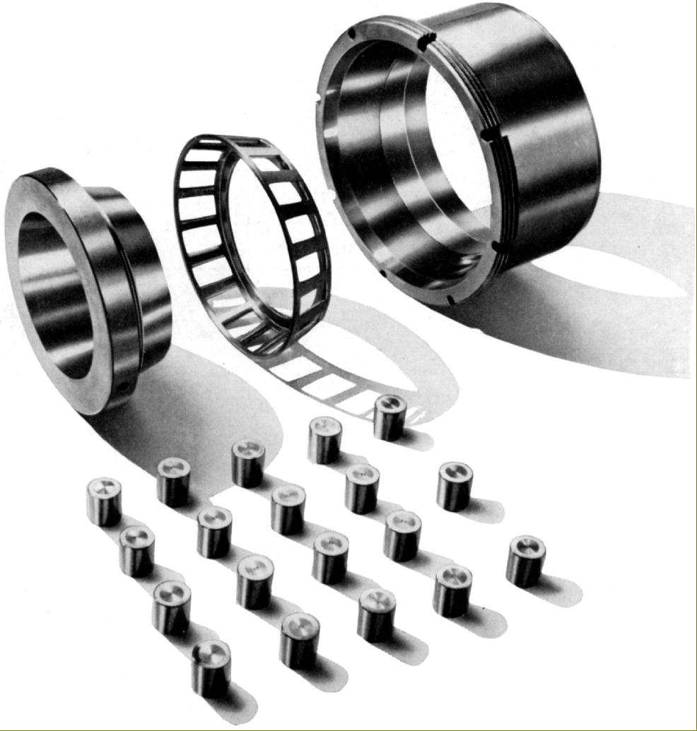
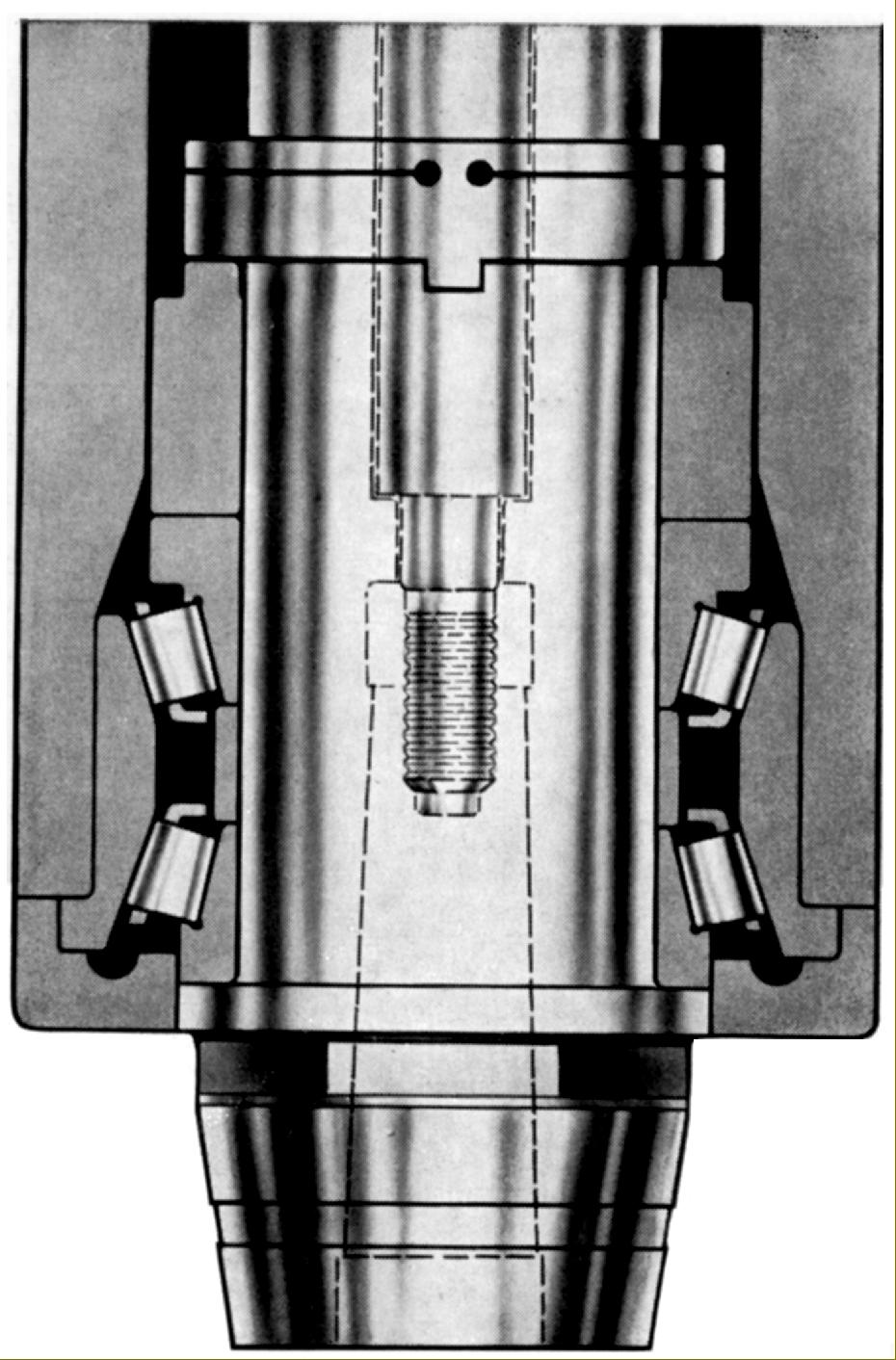
With 8 h.p. available - and both high speeds and rapid metal-removal rates possible - the three spindle bearings were necessarily of a special type being reinforced, capable of taking exceptional stresses while maintaining accuracy and, of course, manufactured by SIP themselves. As large machines, the 6A and 7A had a suitably impressive boring capacity of 12 inches (300 mm) and drilling in steel of 2.375" (60 mm).
Positional accuracy was to within 0.00004" (0.001 mm) and obtained by use of the same kind of photo-electric device used on contemporary SIP dividing machines and electronic comparators. The necessary electronic control equipment and magnetic drum memories were housed in a separate compartment, intended to be located remote from the machine and its vibrations (such as they were)
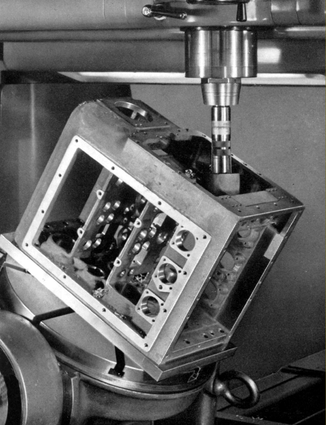
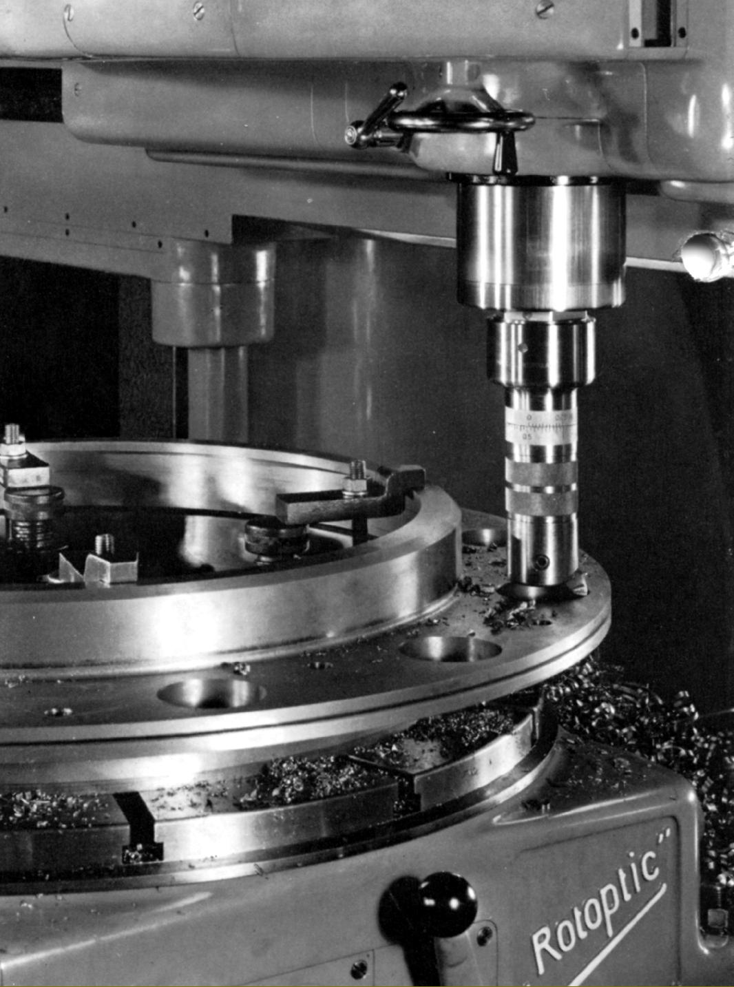
As for all SIP machines, a wide range of accessories was, of course, available, including a choice of appropriately sized PD, PI and Rotoptic heavy-duty plain and tilting rotary table (with optical or vernier scales) and a very wide range of drills, cutters, cutter holders and micro-precision boring heads.
With a large control box mounted at the rear, most versions of the Hydroptic (unless otherwise equipped) had a considerable front-to-back depth: the 6A measured 150" (3810 mm) for the European version and 160" (4065 mm) for American-market models - and a width of 92.5" (2345 mm) common to both. The Hydroptic-6A weighed around 19,000 lbs (8600 kg). Although dimensionally not much larger - the respective depth figures being 147" (3740 mm) and 177" (4490 mm) and a width of 110" (2785 mm) - the 7A weighed considerably more - a massive 29000 lbs (13000 kg) net or, in plain English, 13 tons. 6A and 7A pictures continued here
Two unusual versions of the 6A-DIR and 7A-DIR were produced (though it is reported that only ten of each were made) built to the specification of a three-coordinate measuring machine. Sold as the Superoptic-6AM and Superoptic-7AM, they had electronics built in to put the measuring line in the middle of the "pickle fork" - to within an accuracy of 0.000005"..
|
|