|
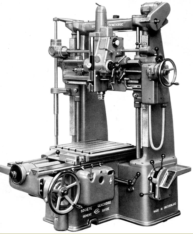
SIP jig borer No. 4G
An older machine (similar in appearance to those made in the 1930s and discontinued by the very late 1950s) this was the middle version of the three post-WW2 SIP models with conventional built-in measuring screws and micrometer heads (i.e. without the incorporation of a precision standard scale). Considerably larger and some 72% heavier than the 3K, it had a 27.5" x 23.675" (700 mm x 600 mm) table with 24" of longitudinal travel and with a lateral movement of 20" (500 mm) on the head. As the cross-rail could be elevated through 23.625" (600 mm) on enclosed, positively lubricated screws, a generous 31.5" (800 mm) could be set between table top and spindle nose. Boring capacity, at 9", was also substantially increased over the 3K with drilling limits of 2" in cast iron and 1.5" in steel.
Fully enclosed, the table and spindle carriage feed-screws were fitted with huge (and almost totally enclosed) micrometer dials that incorporated the SIP automatic vernier correction mechanism. A clever, highly effective arrangement invented during the 1920s, this ensured the accuracy of the complete machine was greater than that of its precision feed-screws. After the machine was assembled, any errors in the movements of table and cross-slide were assessed with great accuracy by comparison with a standard scale of a type similar to those prepared for use in National Measuring Laboratories. A "curve of errors" was prepared and reproduced, in an enlarged form, on a strip of hardened steel that was fixed to one edge of the table and work-head slides. As the slides moved, a small lever followed the strip's profile and transferred its movements, via a long rod held in brackets, to a lever at the other end connected to a sliding vernier scale secured next to the rim of a micrometer drum. Thus, for any position of table or head, a corrected reading was automatically obtained - though care in taking the vernier reading was, of course, essential. Thus equipped, the jig borer was able to provide coordinate readings down to 0.00005" (0.001 mm), though with separate auxiliary ruler scales provided to cope with rapid changes when making long-travel, coarse settings. Using the standard SIP method of calculating accuracy, the displacements of table and spindle-saddle could be held to within 0.0002" (0.005 mm). Power traverse was fitted to the table - using a 1 h.p. motor - and also, with a ¾ h.p. motor, to the cross-rail, the latter having two locking clamps operated simultaneously by the operation of one lever. For use in regular boring or production work, a useful six rates of power spindle feed were fitted: 0.001, 0.002, 0.003, 0.004, 0.008 and 0.012" (0.025, 0.05, 0.075, 0.1, 0.2 and 0.3 mm) per revolution of the spindle.
As on all jib borers made by the Company, the spindle ran in special super-precision ball and roller races of SIP manufacture, the rollers and races being "specular ground" to better than 1 micro-inch (0.25µ) by a special process that eliminated the need for further finishing. The bearing rollers had their diameter and concentricity consistent to within 4-millionths of an inch (0.1µ). At the signing-off test, the maximum permitted eccentricity at the spindle nose was 0.00008" (0.002 mm) and the spindle assembly was not allowed to increase in temperature by more than 10°C during a 24-hour run at high speeds. Bored with a No. 4 Morse taper, the spindle was also formed on its outside with a SIP taper in the largest size available, a 4e. Powered by a 3 h.p. 3-phase motor, the drive had an astonishing total of 20 spindle speeds from a low of 50 through 60, 70, 85, 110, 130, 150, 185, 230, 280, 350, 425, 480, 600, 750, 920, 1065, 1300, 1630 to a maximum of 2000 r.p.m. Coolant was part of the standard equipment, the motor, tank and pipework being built neatly into the main body of the machine.
As for all SIP machines, a wide range of accessories was, of course, available, including a choice of appropriately sized PD, PI and Rotoptic heavy-duty plain and tilting rotary tables (with optical or vernier scales) and a very wide range of drills, cutters, cutter holders and micro-precision boring heads..
With an overall front-to-back measurement of 82" (2080 mm), a width of around 80" (2035 mm) the 4G weighed approximately 6750 lbs (3050 kg) net..
|
|