 |
|
|
|
|
|
|
|
|
|
|
|
|
|
|
|
|
|
|
|
|
|
|
|
|
|
|
|
|
|
|
|
|
|
|
|
|
|
|
|
|
|
|
|
|
|
|
|
|
|
|
|
|
|
|
|
|
|
|
|
|
|
|
|
|
|
|
|
|
|
|
|
|
|
|
|
|
|
|
|
|
|
|
|
|
|
|
|
|
|
|
|
|
|
|
|
|
|
email: tony@lathes.co.uk
Home Machine Tool Archive Machine-tools Sale & Wanted
Machine Tool Manuals Catalogues Belts Books Accessories
SIP Hydroptic 8 Jig Borer
Société Genevoise d'Instruments de Physique
Operation & Maintenance Manuals are available for most SIP Jig Borers
SIP Home Hydroptic 6A & 7A Jig Borer 1-H Jig Borer 2P
Jig Borer 3K Jig Borer 4G Jig Borer 5E Jig Borer 8P
Accessories Jig Borers 1920s No. 2C and No. 3 Tooling Cabinet
Very similar to 7A-Hydroptic - and with the same size and travel of table, head side-to-side travel - and an identical design of table-drive system and measuring equipment - the 8P differed in having two heads, one vertical and the other horizontal. Designed for production purposes, rather than jig boring (hence the suffix "P") it's intended use was akin to that machine of an entirely different configuration, the wonderful DeVlieg 'jig miller'. Able to perform heavy-duty milling as well as fine surface finishing (down to 7 or 8 micro-inches (0.0002 mm) the 8P could drill holes up to 23/8" (60 mm) in solid cast iron and bore them up to 10-inches (250 mm) in diameter.
The stepless range of power milling feeds for the table were set at a lower maximum than the 7A - 12" (300 mm) per minute- though the rate of rapid traverse was identical and also equipped with a slow feed for bringing up to the final setting. Even for this large machine the Société Genevoise d'Instruments de Physique guaranteed an accuracy for all displacements of work-table and spindle head of 0.0002" (0.005 mm).
Because of the side-mounted motor for the second head, the maximum clearance between spindle end and table top was reduced by 6 inches (from 50 inches) as was the width between the (heavier) uprights. The need to provide wide and robust ways to elevate the heavy side head accounted for most of the significant dimensional differences.
Both heads had an identical, two-speed 3-4 h.p. motor (a considerable drop on the 8 h.p. fitted to the 6A and 7A) with the vertical having 18 speeds from 40 to 2000 r.p.m. and the horizontal the same range but two fewer speeds. Made from heat-treated and seasoned steel, the spindles ran in three SIP-manufactured high-precision taper roller bearings and carried a special SIP-50 internal taper. Rollers and races were "specular ground" to better than 1 micro-inch (0.25µ) by a special process that eliminated the need for further finishing. The bearing rollers had their diameter and concentricity consistent to within 4-millionths of an inch (0.1µ). At the signing-off test, the maximum permitted eccentricity at the spindle nose was 0.00008" (0.002 mm) and the spindle assembly was not allowed to increase in temperature by more than 10°C during a 24-hour run at high speeds.
Unlike the company's smaller machines there was no external taper fitting, the inside one, a SIP 50, being more than adequate for all tool-holding requirements. Two popular tooling fitments were the FS Boring head, with a range from 5" to 10" (125 mm to 250 mm) and the Type P50 high-precision toolholder, a version that could be used for a wide variety of tasks including facing, turning and grooving, etc.
Spindle travel was 12" (300 mm) with eight rates of feed available, identical for both heads at 0.001" to 0.012" (0.025 to 0.3 mm) per revolution. Automatic disengage stops were fitted that allowed a job to progress without intervention by the operator. For more accurate setting of depth cuts, the facility to mount either slip gauges or, optionally, a dial gauge reading to 0.0005" was provided. However, the slip-gauge method would have slowed down work setting appreciable and, as an expensive option, the vertical head could be fitted with a standard scale, micrometer drum and vernier should the 8P be pressed into service as a three-coordinate measuring machine (for measuring and checking jobs completed on other machine tools). A further use for the 8P was as a (limited capacity) horizontal borer, an outboard bearing support being offered that provided a guide for boring bars - with an optical alignment device being fitted to aid the operator.
As a machine that occupied a considerable floor area, it was necessary, for safety and efficiency, to have some controls duplicated: spindle rotation could be managed from either side of the head and the right-hand end of the cross beam - as well as from the left side of the bed. In addition, spindle speed-change and table-feed levers were duplicated at each side of the head with control of the rapid quill feed and spindle slow speeds duplicated on the cross beam and left-hand side of the bed.
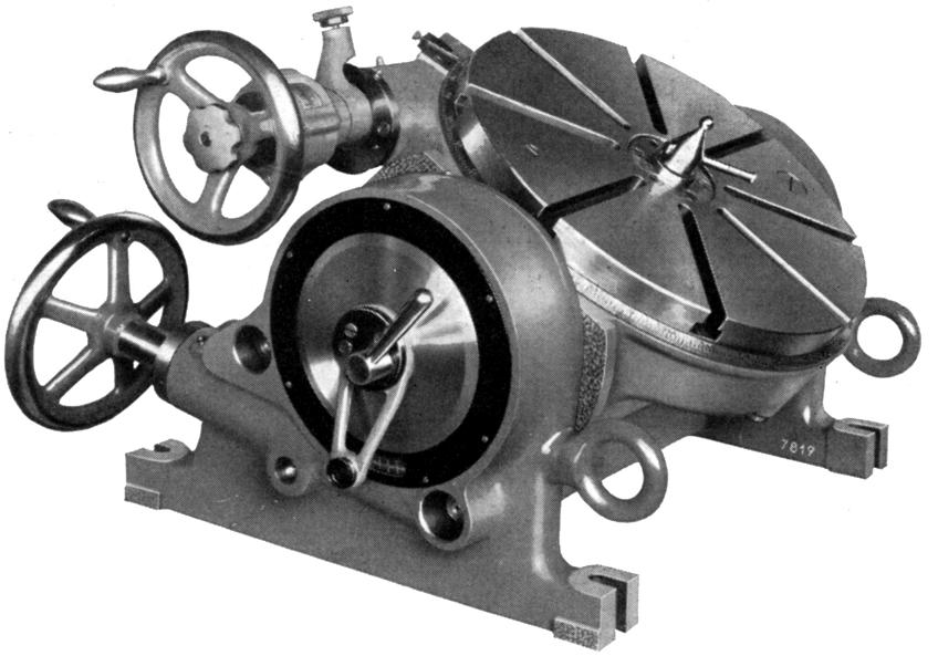
A number of useful accessories was listed including the massive 31.5-inch (800 mm) motor-driven "Rotopic-6" Rotary table with optical read-outs from a built-in master circular scale. This model was designed to cope with the rigors of machining heavy jobs and rotated on a special large-diameter ball bearing. Readings down to 10 minutes of arc could be set under motor power with a further improvement down to 1 second being obtained by a handwheel with a vernier scale. The final setting was achieved by using a microscope to centre a projected line from the master circular scale between a fork on the viewing screen.
With a front-to-back depth of 164" (4150 mm) and a width of 122" (3100 mm) the Hydroptic-8P had a net weight of approximately 38,000 lbs (17100 kg)..
|
|
|
|
|
|
|
|
|
|
|
|
 |
|
|
|
|
|
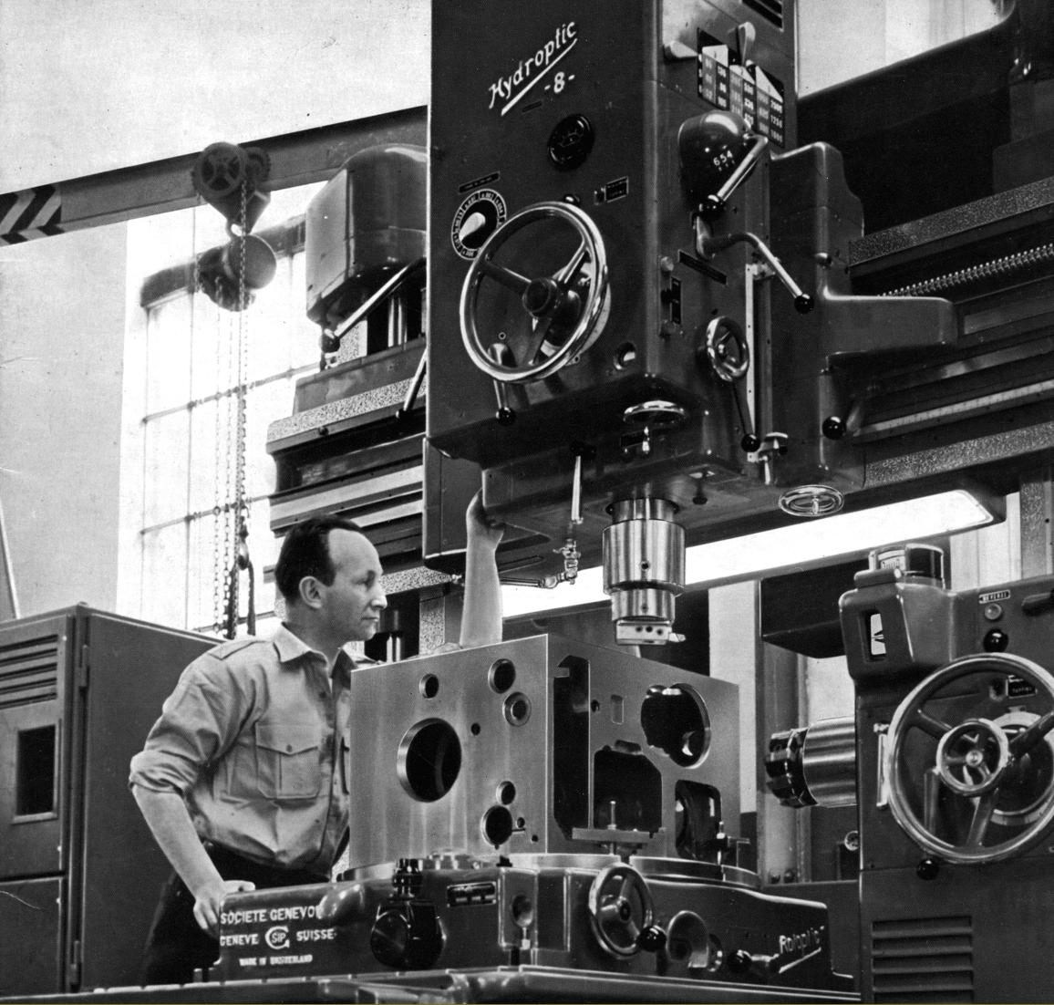
SIP Hydroptic 8P production jig borer
|
|
|
|
|
|
|
 |
|
|
|
|
|
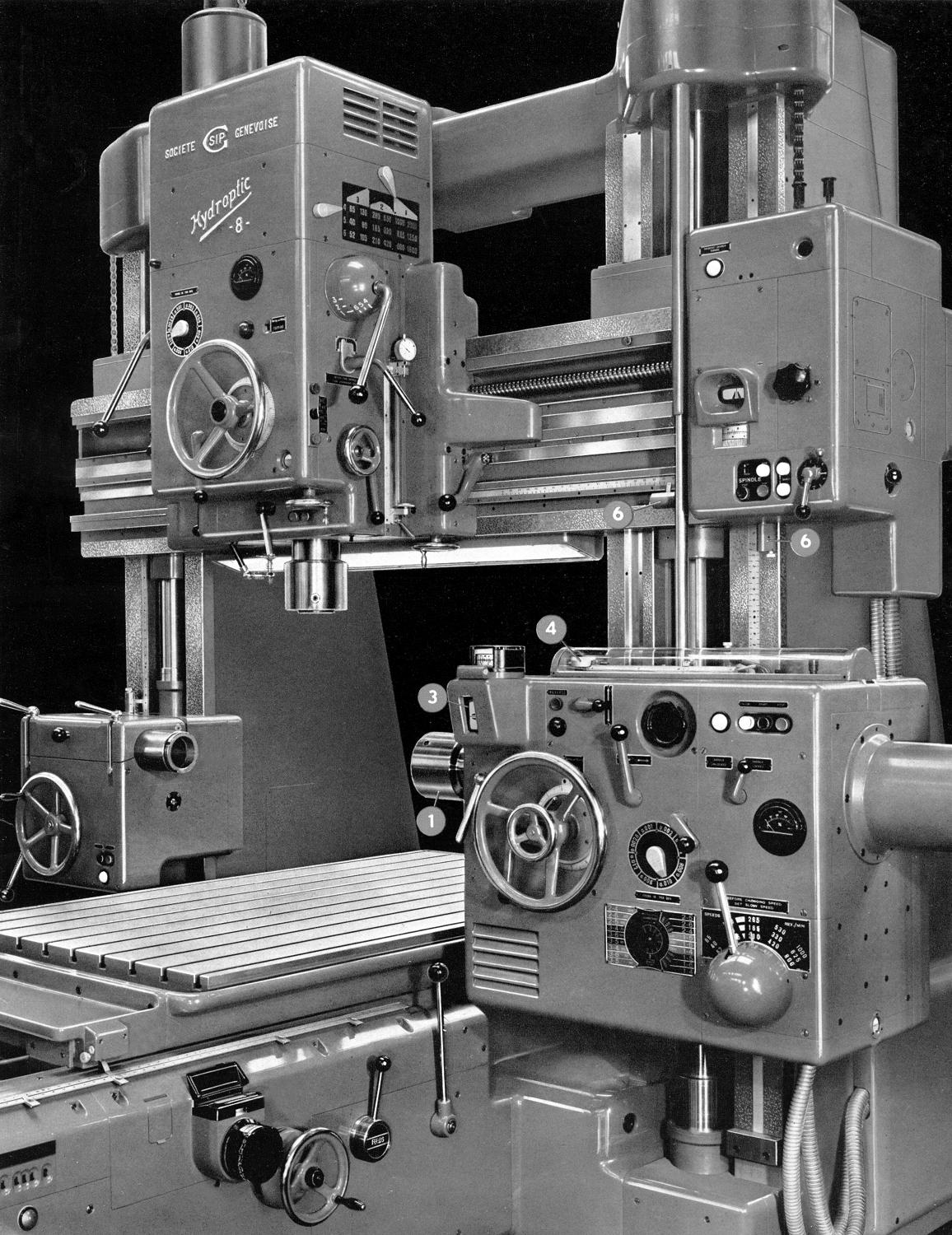
A clear view of the vertical and horizontal head arrangement of the SIP Hydroptic 8P
|
|
|
|
|
|
|
 |
|
|
|
|
|
|
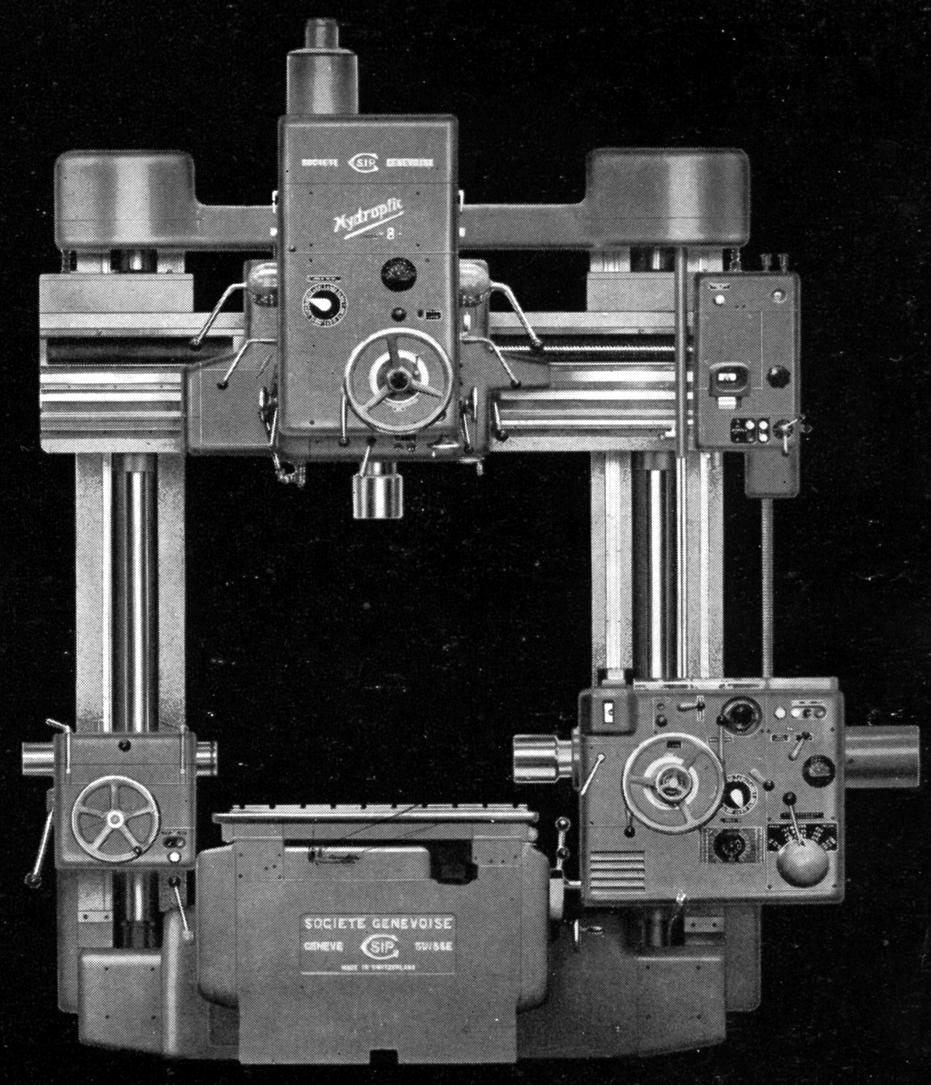
SIP Hydroptic 8P front elevation
|
|
|
|
|
|
|
|
|
|
|
|
 |
|
|
|
|
|
|
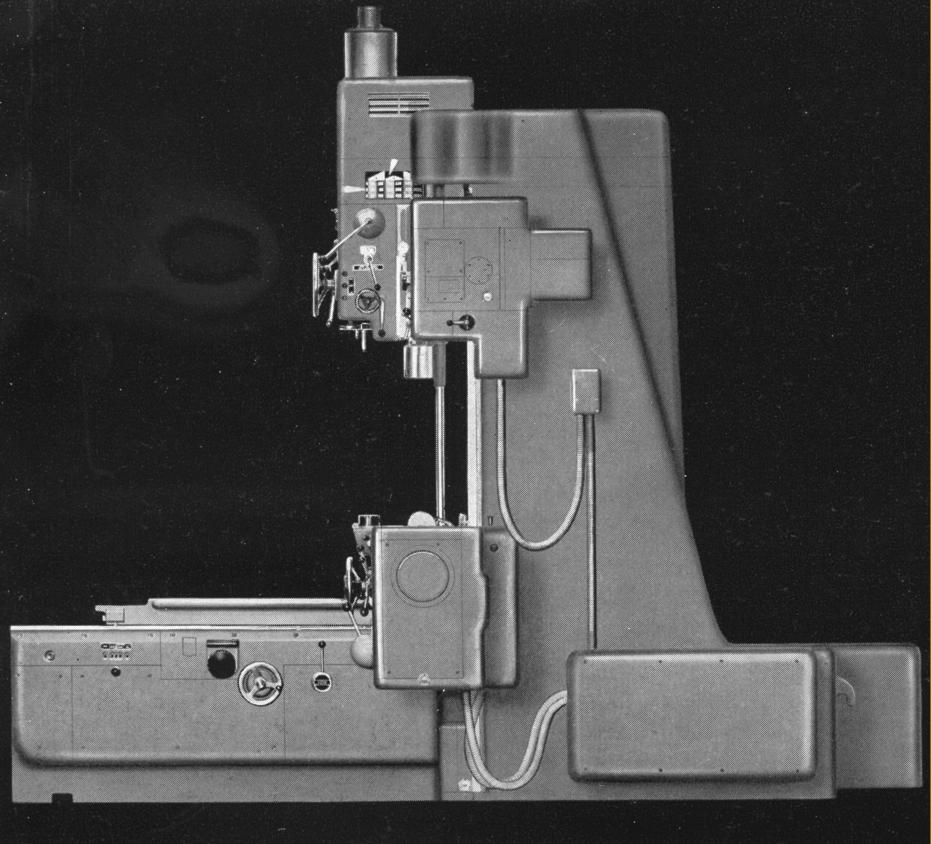
SIP Hydroptic 8P side elevation from that opposite to the horizontal head
|
|
|
|
|
|
|
 |
|
|
|
|
 |
|
|
|
|
|
|
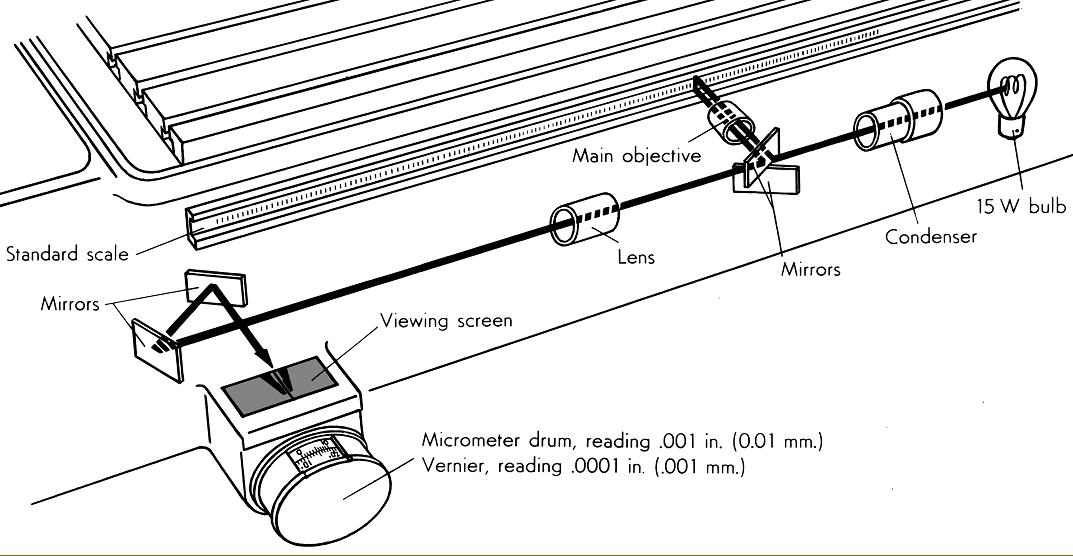
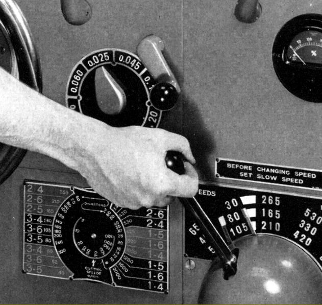
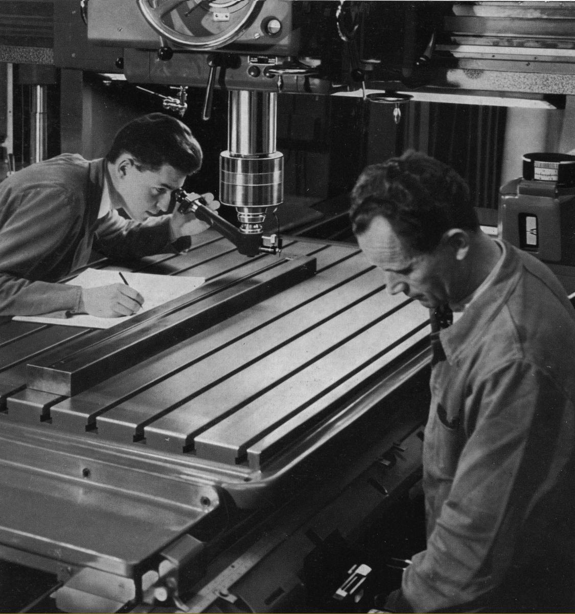
Schematic view of the system used to determine table position of the SIP jig borers when fitted with standard scales. The first position was read from ordinary rulers mounted alongside each slide - this could be to within 0.1"- then from a micrometer drum (down to 0.001") with a vernier scale providing a further increase in accuracy to within 0.0001". The final setting down to 0.00005", was achieved by centring a line, projected from the standard scale, between a fork on the viewing screen. The last setting was aided by a slow-feed handwheel
|
|
|
|
|
|
|
 |
|
|
|
|
|
|
|
|
|
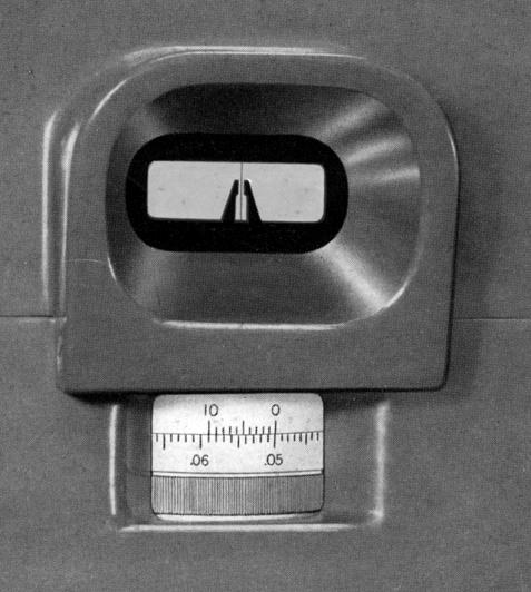
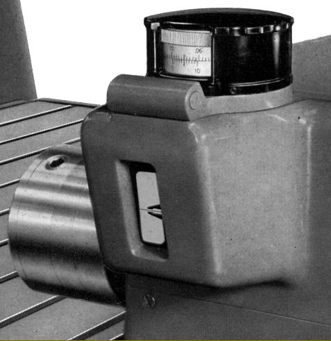
Viewing screen with, above it, the micrometer drum with vernier scale.
|
|
|
|
|
|
|
|
|
 |
|
|
|
|
|
|
|
|
|
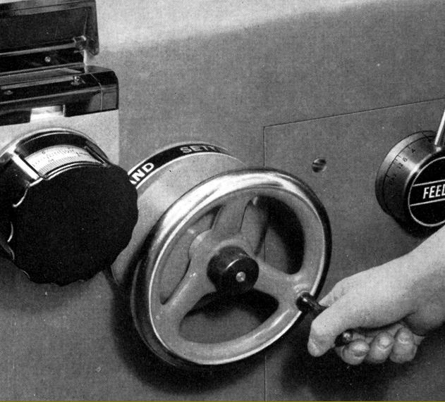
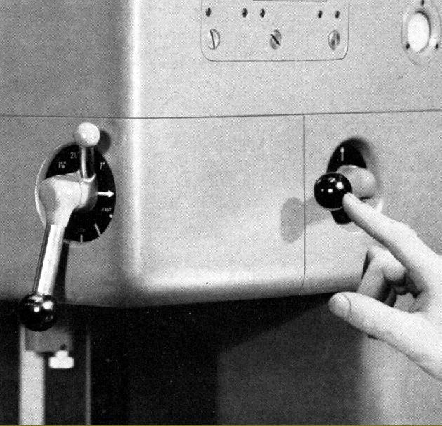
Fine-feed handwheel for final centring of the projected line from the standard scale between the fork on the viewing screen.
|
|
|
|
|
|
|
|
|
 |
|
|
|
|
|
|
|
Table feed-speed selector lever
|
|
|
|
|
|
|
|
|
 |
|
|
|
|
 |
|
|
|
|
|
|
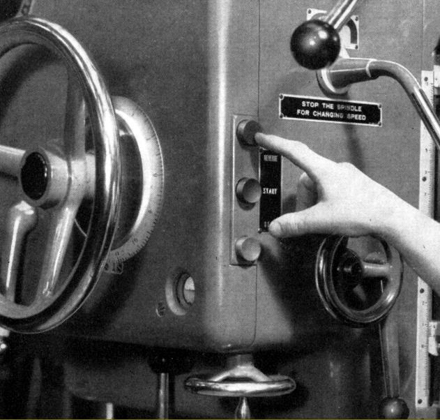
Spindle start, stop and reverse could be controlled from either side of the head, from the right-hand end of the cross beam as well as from the left-hand side of the bed. In addition, spindle speed-change and table-feed levers were duplicated at each side of the head
Individual controls for the rapid quill feed and spindle slow speeds could be operated from either the cross beam or left-hand side of the bed.
|
|
|
|
|
|
|
 |
|
|
|
|
|
|
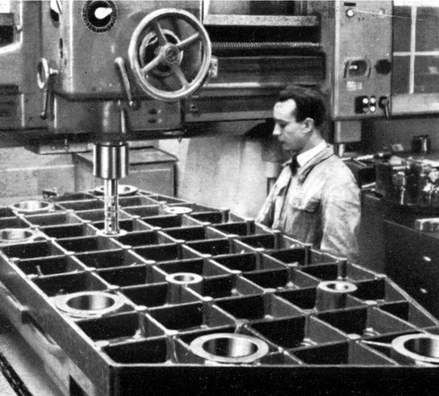
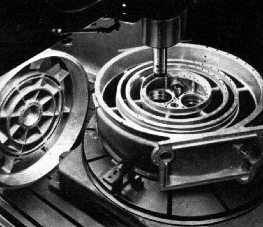
Boring a large jig to be used for jig-drilling marine gears
|
|
|
|
|
|
|
 |
|
|
|
|
|
|
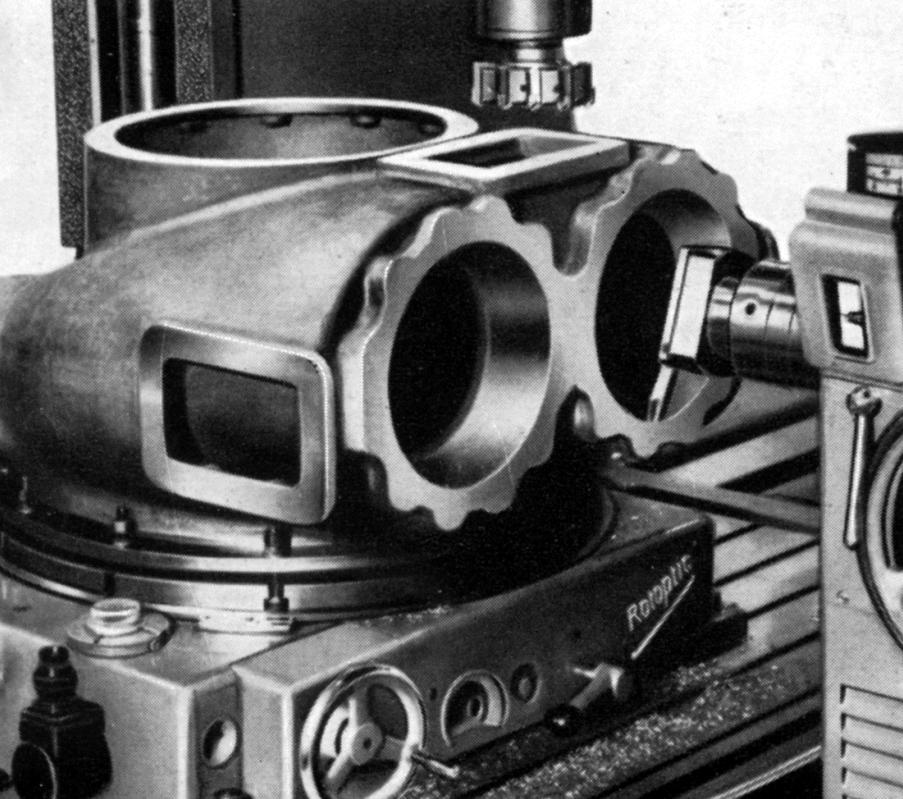
Boring the housing used to hold reduction gears on a jet engine assembly
|
|
|
|
|
|
|
 |
|
|
|
|
|
|
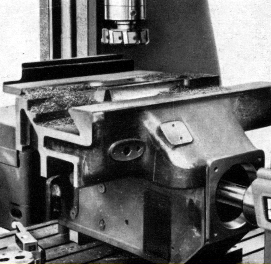
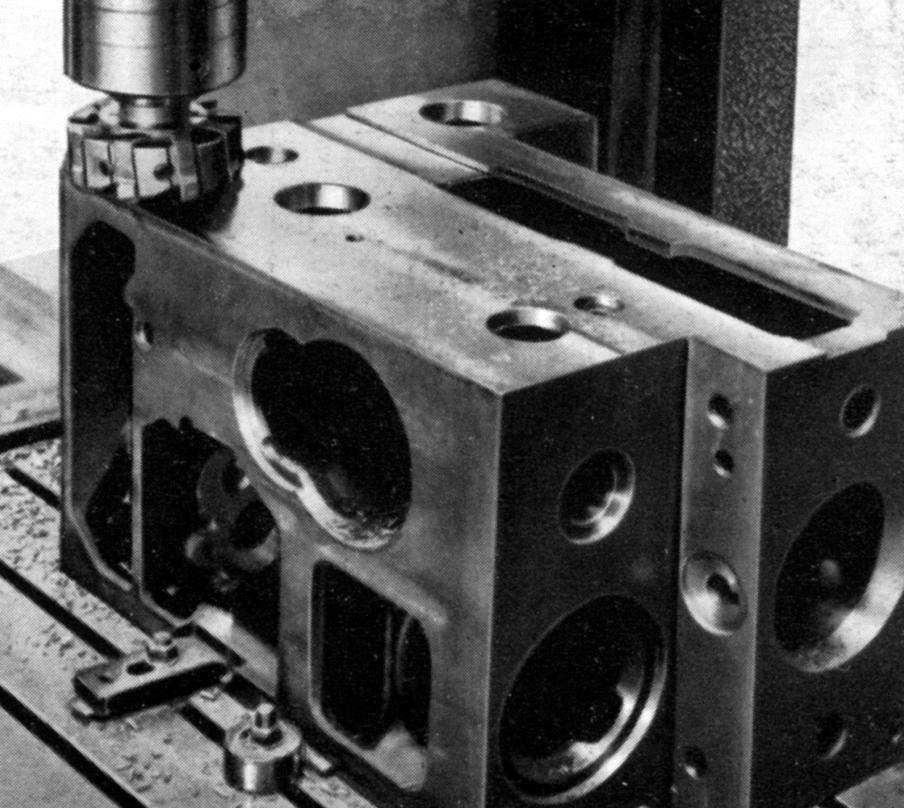
Machining the base of a machine-tool headstock
|
|
|
|
|
|
|
 |
|
|
|
|
|
|
Machining a gas turbine inlet housing using the Rotoptic-6 rotary table
|
|
|
|
|
|
|
 |
|
|
|
|
|
|
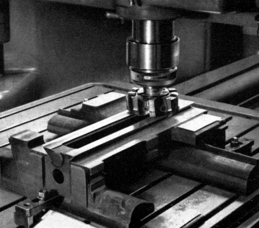
Milling the slides on a lathe saddle
|
|
|
|
|
|
|
|
|
|
|
|
 |
|
|
|
|
|
|
The headstock from a precision machine tool being machined
|
|
|
|
|
|
|
 |
|
|
|
|
|
|
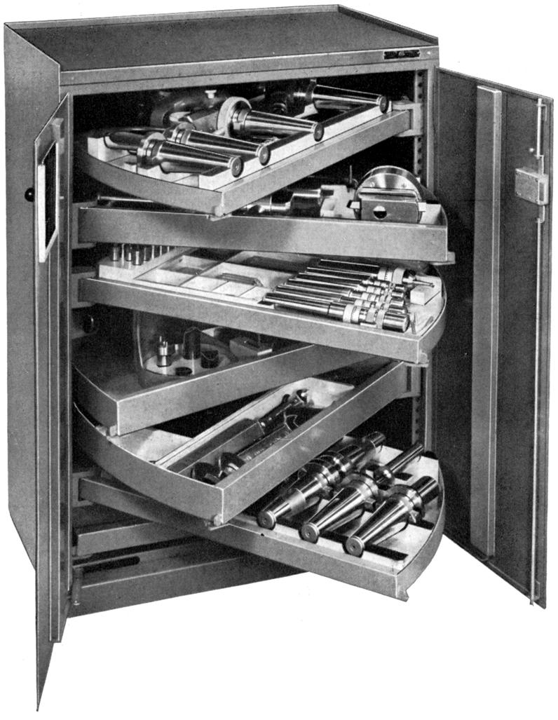
Typical SIP 40" x 30" x 20" (1000 x 750 x 500 mm) tool cabinet with seven very heavy-duty swing-out shelves each able to take a load of 200 lbs (100 kg). Six of the shelves were lined with felt to protect the edges of cutting tools.
|
|
|
|
|
|
|
 |
|
|
|
|
|
|
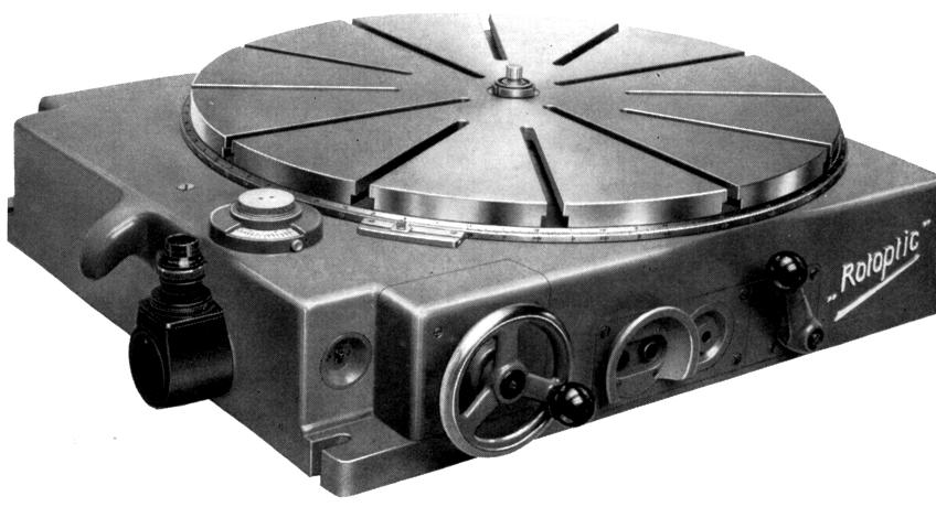
Motor-driven "Rotoptic-6" Circular Dividing Table 31.5-inches in diameter (800 mm) with optical read-outs from a built-in master circular scale. This massive unit was designed to cope with the rigors of machining heavy jobs and rotated on a special large-diameter ball bearing. Readings down to 10 minutes of arc could be set under motor power with a further improvement down to 1 second being set by a handwheel with a vernier scale. The final setting was achieved by using a microscope to centre a projected line from the master circular scale between a fork on the viewing screen.
|
|
|
|
|
|
|
 |
|
|
|
|
|
|
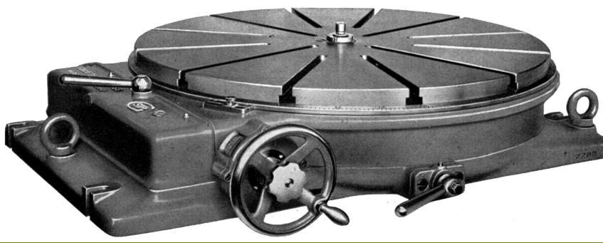
Type PD-6 Mechanical Circular Dividing Table. A conventional mechanical version of the Rotoptic-6 that used worm-and-wheel gearing. Readings down to 1 second of arc could be set on the vernier scale of the micrometer dial attached to the worm shaft.
|
|
|
|
|
|
|
 |
|
|
|
|
|
|
Type PI-5 Tilting Rotary Table with worm-and-wheel gearing and 17.5-inches in diameter (450 mm). This unit allowed the boring of holes and milling of faces to be accomplished at compound angles. Rotation angles were read to within 1 second of arc with tilt angles able to be set to within 1 minute of arc on the vernier
|
|
|
|
|
|
|
 |
|
|
|
|
|
|
|
|
|
|
|