|
Home Machine Tool Archive Machine-tools Sale & Wanted Mikron Home Lathes on Stands Lathes & Beds Headstocks Slide Rests & Capstan Units Tailstocks & Drilling Attachments Mikron Lathe Photographs Mikron Thread-chasing Lathe Large Mikron Millers Small Mikron Millers |
|
|
|
|
||
|
|
||
|
|
||
|
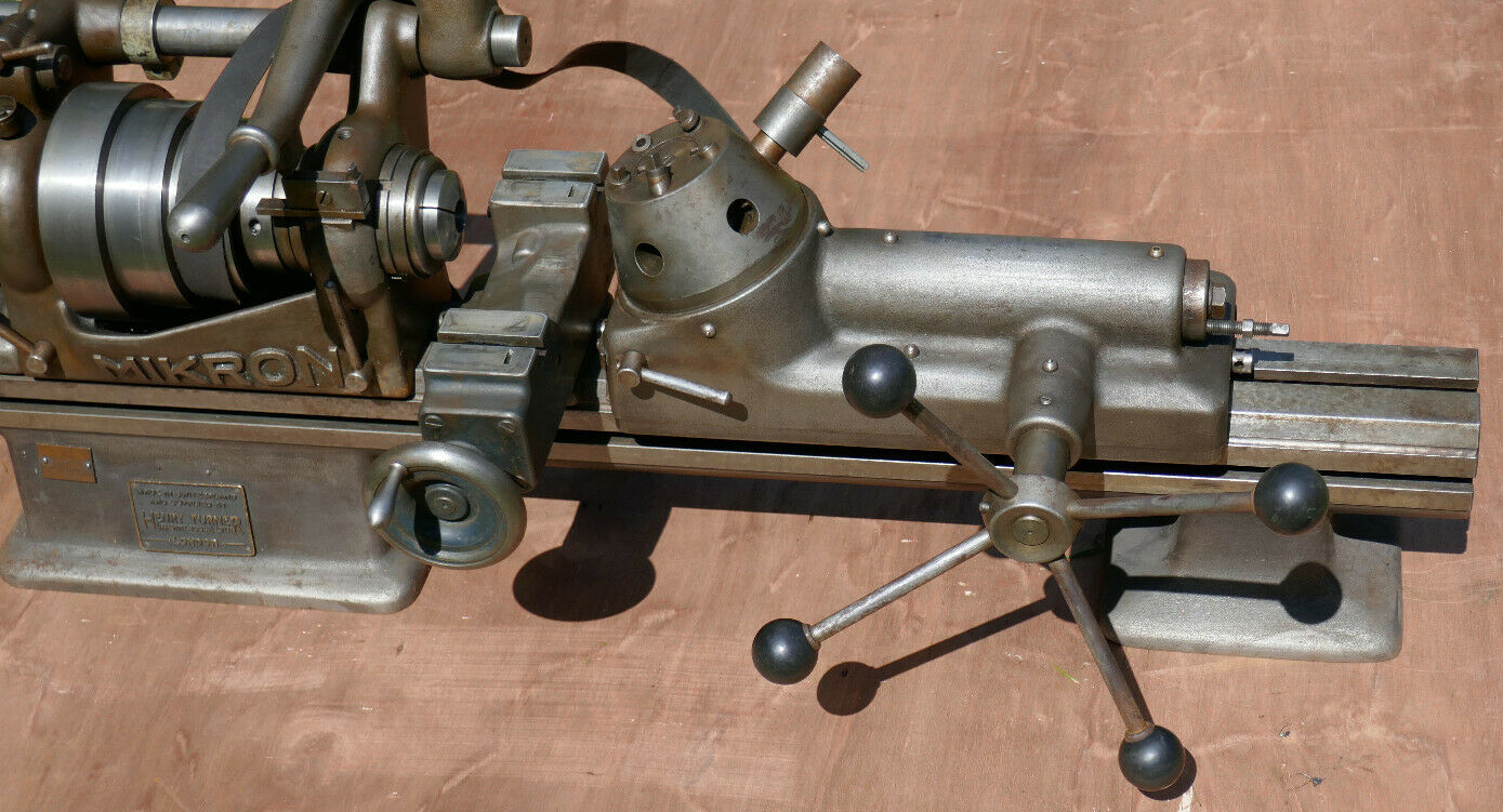
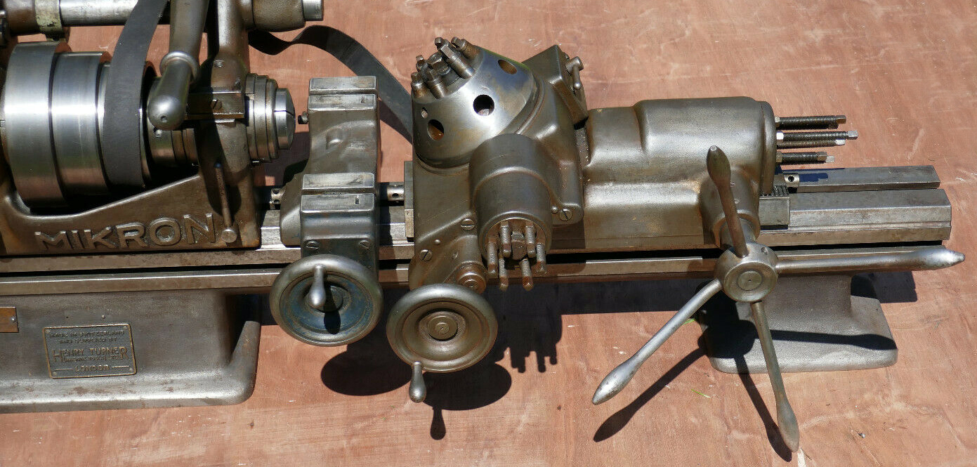
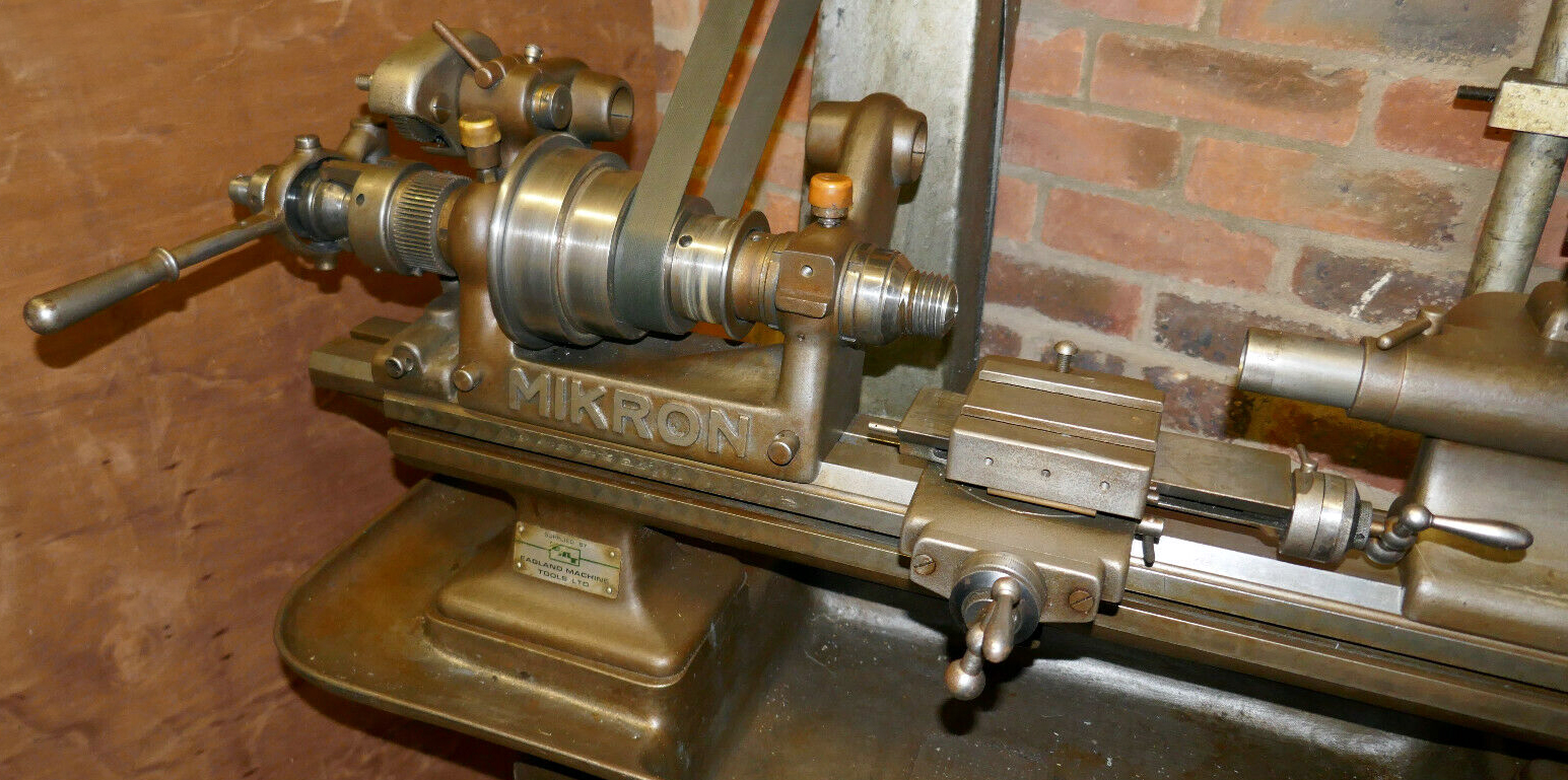
A very rare attachment, Mikron Slide No. 35--for more complex work, and the use of unusual tools and toolholders an 80 mm travel, 6-station turret unit was listed. This had the rotating head mounted on a 40 mm travel cross slide (operated by a handwheel and coarse, quick-action thread) together with a six-position rotary stop. Instead of being rotated by the longitudinal sliding action the turret (bored for 18 mm tools) was indexed by a lever on top that simultaneously unlocked and turned it. |
||
|
|
||
|
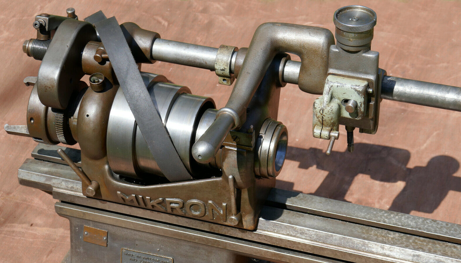
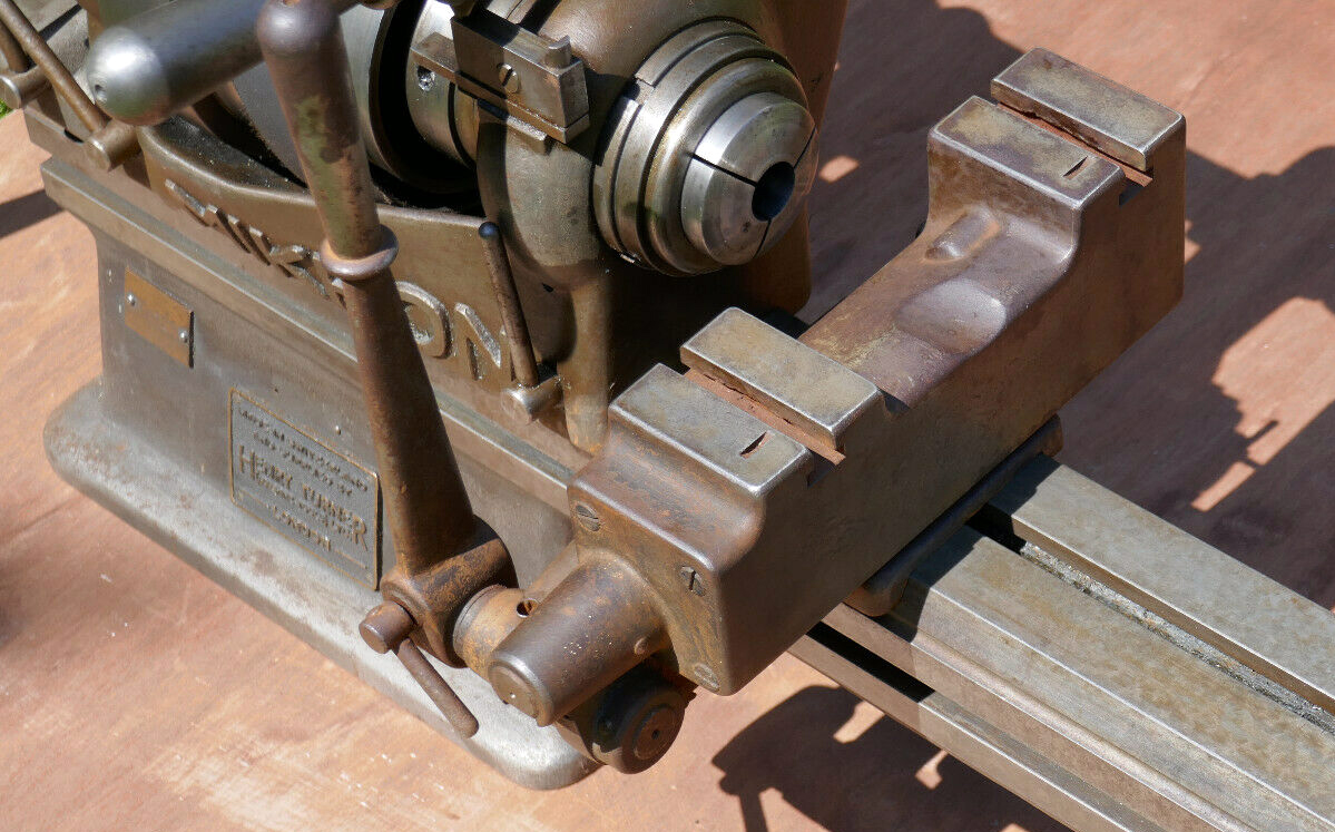
later type. This slide was usually arranged with a coarse, quick-action screw to the cross travel but with a fine feed to the top slide |
||
|
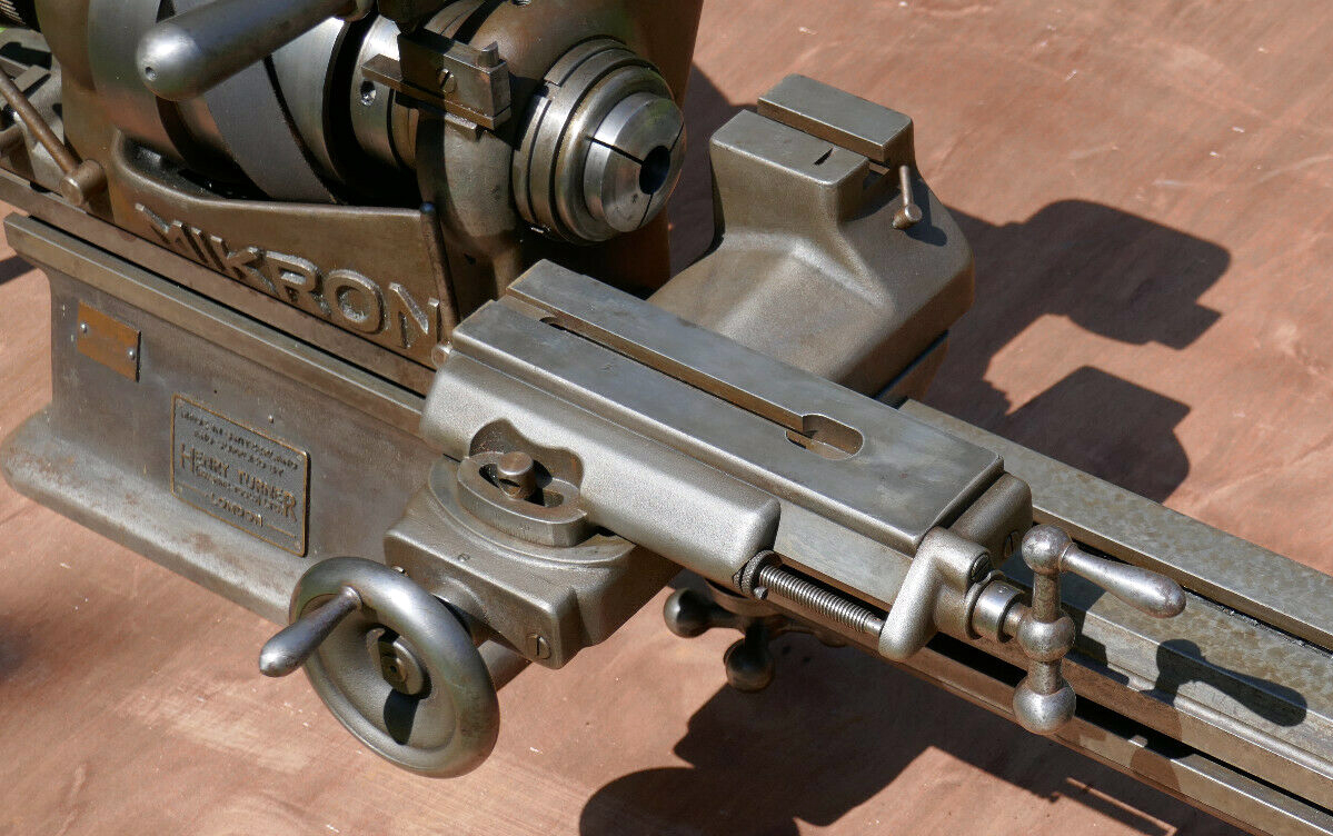
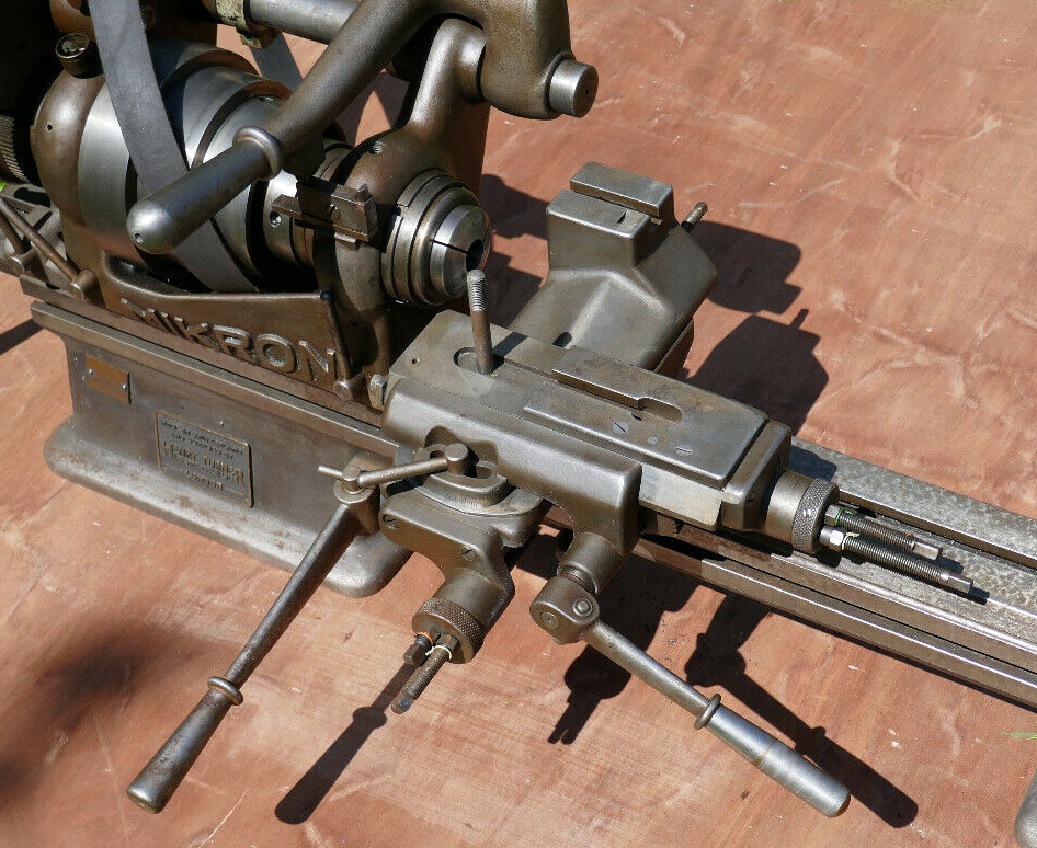
Mikron slide rest No. 25 - for more complex machining operations this was a compound type with lever feeds to both motions and a rear toolpost on the cross slide. Each axis was fitted with an adjustable 3-position rotating stop and the extra-heavy top slide with its wide, bevelled ways could be swung - but only through a total of 30°. If greater flexibility in turning was required - perhaps a mixture of repetition and hand-finishing work - the slide could be supplied as the No. 26 with a fine-feed screw feed to the top slide - though this meant a reduction in the number of stops to just one per axis. If screw feeds were need in both directions the slide could be fitted with a cross-feed screw of coarse pitch (and hence rapid feed) and ordered under part No. 27. |
||
|
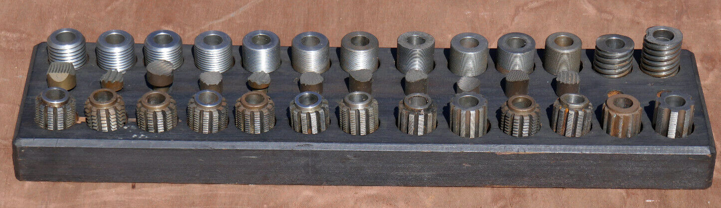
An extensive set of "master threads" for the chase-screwcutting attachment complete with the hobs necessary to make replacements. Mikron were better known for their gear-cutting machines rather than lathes |
||
|
|
||
|
Tailstocks & Drilling Attachments Mikron Lathe Photographs Mikron Thread-chasing Lathe Large Mikron Millers Small Mikron Millers |
||