|
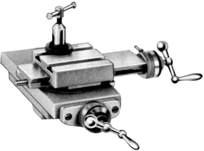
Mikron offered some eleven different slide rests to cover the needs of horological work, tool making and production. For ordinary turning a traditional screw-feed rest (No. 20, above ) was recommended with both top and cross slides (the latter carrying two T-slots) having 90 mm of travel. If a covered top slide was required (to protect the screw and ways from turning dust and swarf and so prolong life and accuracy) the rest could be ordered as No. 21a - though this did involve a reduction in travel to 75 mm. A "heavy-duty" rest was also manufactured and listed as the "reinforced", this having a solid top slide without T-slits and a feed screw of coarser pitch and hence quicker feed. A number of all-lever-operated and combined lever-feed-screw slides were listed, these being intended for production work and able to be combined with other fittings as the job required On all screw-feed slides backlash-adjustable bronze nuts were fitted together with friction-setting micrometer dials calibrated in either 0.001" or 0.001 mm increments) and the top slide could be swivelled through 90° each side of zero. The standard toolpost was a simple "American" type, but adjustable in height by means of a screwed ring - exactly as introduced during the first decade of the 20th century by the American Derbyshire Company on their Webster-Whitcombe type watchmakers' lathes. |
|
|
|
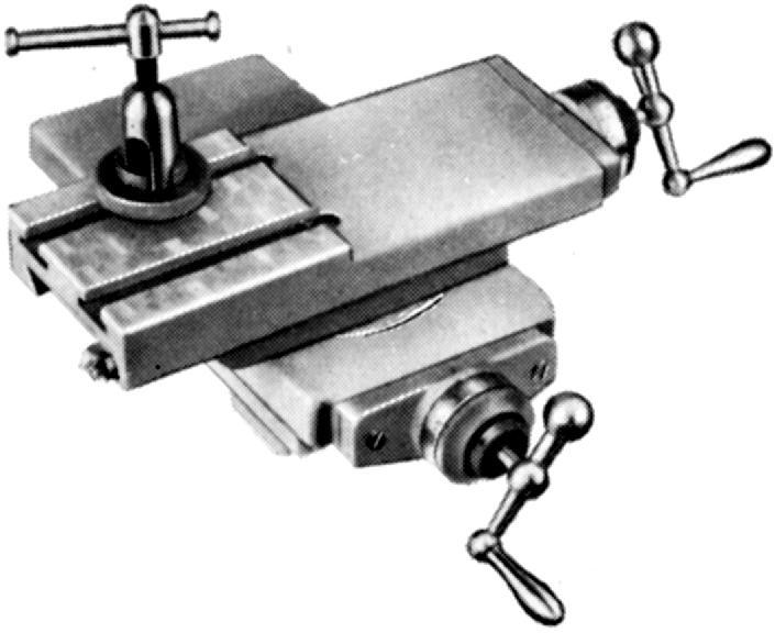
Slide No 22. A heavy-duty, strengthened slide rest with larger-diameter, coarse-pitch feed screws and with an open, non-slotted top slide that was limited to a swivel of 45° each side of the centre mark. The slide was supplied as standard with a heavier, claw-type toolpost (designed to accommodate 10 mm tools) metric-pitch feed-screws and smaller-diameter micrometer dials marked in 0.02 mm intervals. |
|
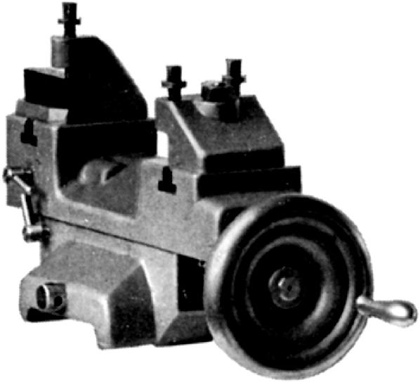
Slide No. 23 - a screw-feed, cut-off production type with coarse-pitch feed-screws (some may have been fitted with double-start threads) that mounted front and rear toolposts and screw-adjustable stops for both forward and backward motions. Three toolposts were provided: two standard and one to take parting-off tools. |
|
|
|
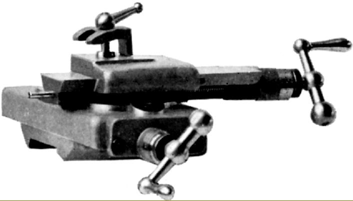
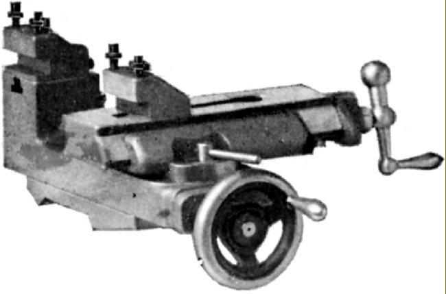
Slide No. 25 - for more complex machining operations this was a compound type with lever feeds to both motions and a rear toolpost on the cross slide. Each axis was fitted with an adjustable 3-position rotating stop and the extra-heavy top slide with its wide, bevelled ways could be swung - but only through a total of 30°. If greater flexibility in turning was required - perhaps a mixture of repetition and hand-finishing work - the slide could be supplied as the No. 26 with a fine-feed screw feed to the top slide - though this meant a reduction in the number of stops to just one per axis. If screw feeds were need in both directions the slide could be fitted with a cross-feed screw of coarse pitch (and hence rapid feed) and ordered under part No. 27. |
||

|
|
||
|
Slide No. 27 - another adaptation of Slide No. 25 with a fine-feed screw feed to the top slide, a coarse, quick-action screw to the cross and a reduction in the number of stops to just one per axis. |
||
|
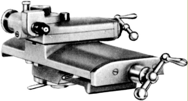
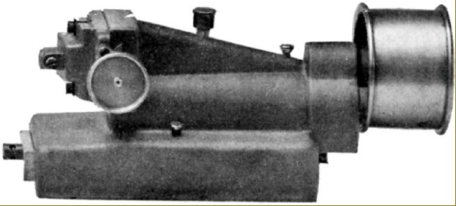
Slide No 28 for grinding - either cylindrical or surface. The top-slide could be rotated through 360°, had a travel of 100 mm of travel and was machined to mount the high-speed grinding and milling spindle No. 66. |
|
Slide, No. 29 - for spherical (ball) turning. This incorporated a top slide rotated by worm-and-wheel gearing and was able to generate spheres of up to 60 mm in diameter with its centre of rotation moveable from 0 to 40 mm. Tools up to 9 mm in diameter could be fitted and the unit could be rotated through 360°. |
|
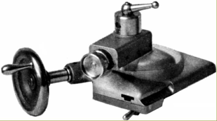
Slide No. 30. This unit was adapted from watchmakers' lathe practice and employed solely for pivot polishing (burnishing). It was mounted on a swivelling base, which could be swung through 45° in either direction, and both slides were fitted with micrometer-adjustable stop screws. The top slide had 15 mm of travel - more than adequate for the jobs likely to be encountered - with the largest diameter of pivot that could be ground being 2 mm. A special tailstock, No. 46 with a swing-action centre, was produced to accompany this fitting. |
|
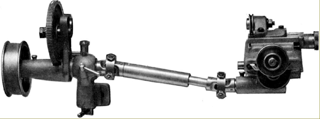
Slide No. 31 - a relieving unit, driven directly by a cam that imparted an oscillating motion, provided to assist with the production of milling cutters. It could accommodate material up to 60 mm in diameter and had a slide travel of up to 25 mm. A bracket, which bolted into the bed's front T-slot, carried the drive part of the unit and included a set of changewheels with 7, 8, 9, 10, 11, 12, 14, 15, 16, 18, 20, 22 and 24 teeth. |
|
Slides No. 32 (above) and No. 33 (below). Both were identical, had 80 mm of travel and were intended for fitting on the compound slide rest No. 21. No 32 carried a 60-hole indexing head (that could be swivelled up to 45°) or a worm-and-wheel driven indexer No. 106. Slide No. 33 was equipped with a milling quill (No. 112) in place of the indexer. |
|
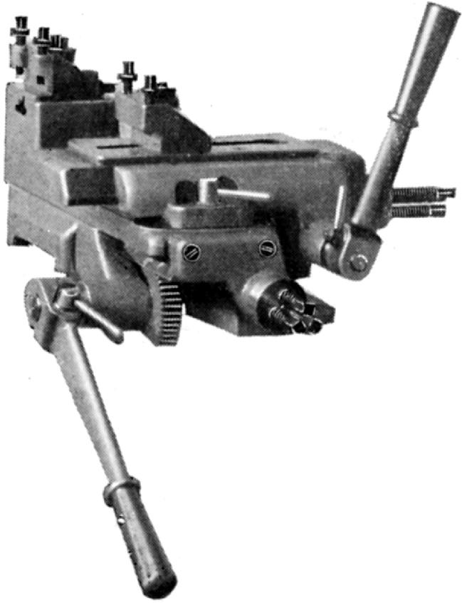
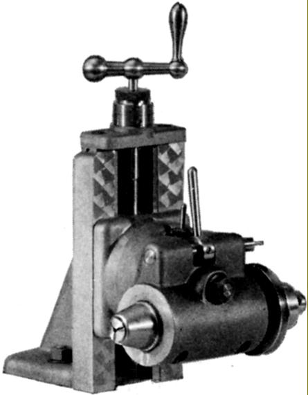
Slide No. 34 - for serious production work a 5-station indexing turret was available. This had a slide travel of 100 mm by rack-and-pinion gearing operated by a 4-spoke capstan handwheel. Bored to accept 18 mm tools the turret was automatically indexed on the return stroke. However, for occasions when the turret needed to be spun round, a small release lever was provided to disengage the pawl. |
|
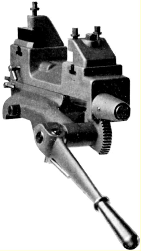
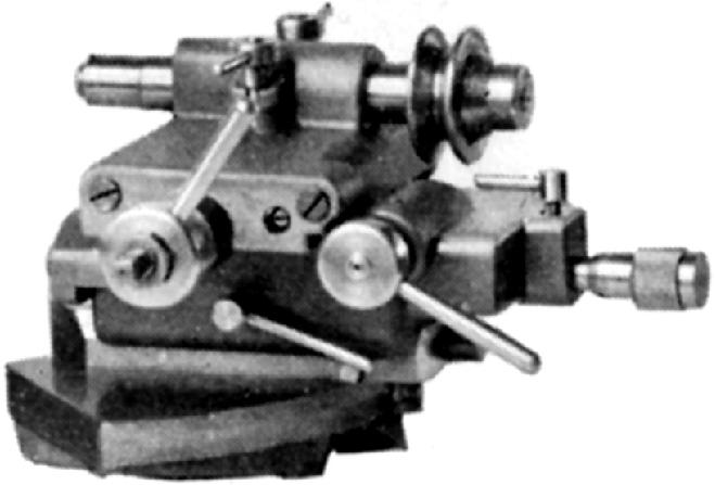
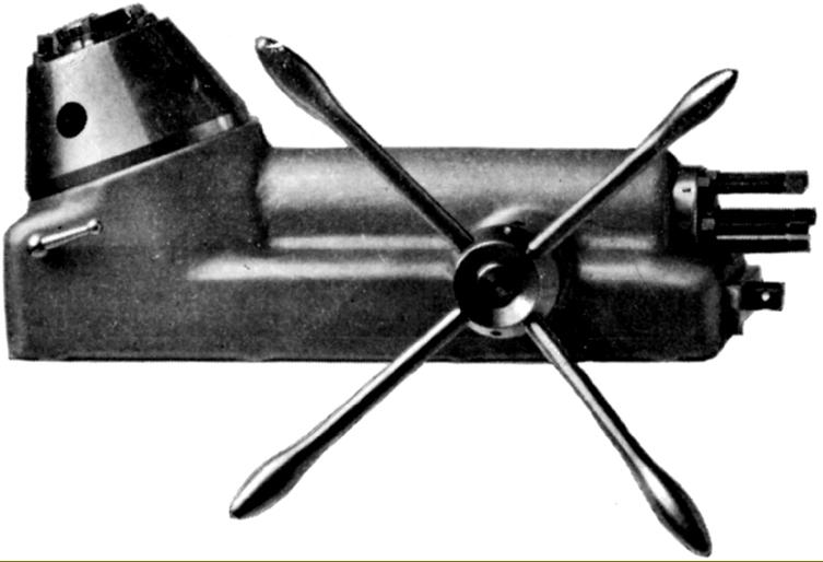
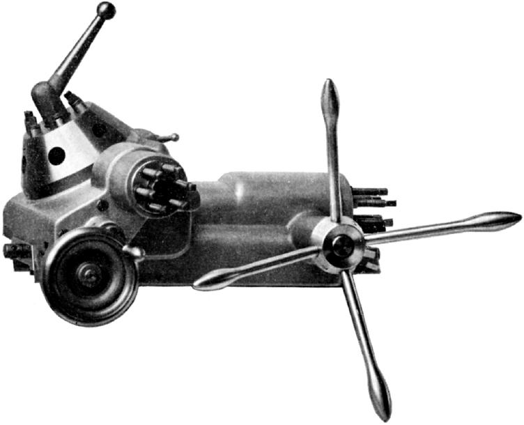
Slide No. 35--for more complex work, and the use of unusual tools and toolholders an 80 mm travel, 6-station turret unit was listed. This had the rotating head mounted on a 40 mm travel cross slide (operated by a handwheel and coarse, quick-action thread) together with a six-position rotary stop. Instead of being rotated by the longitudinal sliding action the turret (bored for 18 mm tools) was indexed by a lever on top that simultaneously unlocked and turned it. |
||
|
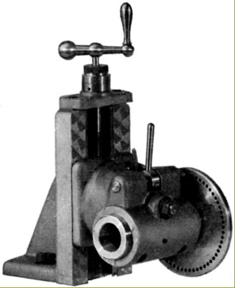
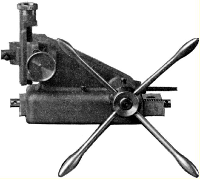
Slide No. 36 - a hand-operated slotting unit with a vertical slide on its end that could also be moved sideways. Travel of the bed slide was 90 mm and movements of the compound slide on the slotting head 40 mm across and 30 mm vertically (the latter two with 0.01 mm micrometer dials on their feed screws). All movements were limited by adjustable stops. The attachment was also offered fitted to a special lathe that used the No. 2a short bed and the No. 16 indexing and swivelling headstock. For serious production use a powered version of the slide was available under accessory No. 37. |
||
|
|
||
|
Slide Rests & Capstan Units Tailstocks & Drilling Attachments Mikron Lathe Photographs Mikron Thread-chasing Lathe Large Mikron Millers Small Mikron Millers Mikron Type 79 Gear Hobber email: tony@lathes.co.uk Home Machine Tool Archive Machine-tools Sale & Wanted |
||