|
|
Founded in Germany during the early years of the 20th century, the Deckel Company's machine-tool business grew out of their involvement with the camera industry. Their specialisation was leaf shutters, using the brand name "Compur", an item widely used by leading manufactures including Hasselblad inside their "Type C" lenses. Deckel also developed the well-known and very successful bayonet lens mount for the Retina Reflex, Voigtlander Bessamatic and Ultramatic cameras - a design that held back, for a while, the invasion of the much cheaper, yet just-as-well-made, Japanese single-lens reflex. By 1984, and with demand for leaf shutters confined to a shrinking market, Zeiss (who owned both Deckel and Alfred Gauthier, makers of Prontor shutters) merged the two firms. Production continued until around 2002 when, due to a final catastrophic fall in demand, a halt was called. From the earliest days of the company Deckel were involved in the manufacture of machine tools, but these seem to have been, from the lack of contemporary advertising literature or in contemporary machine-tool trade journals, for use in their own factories.
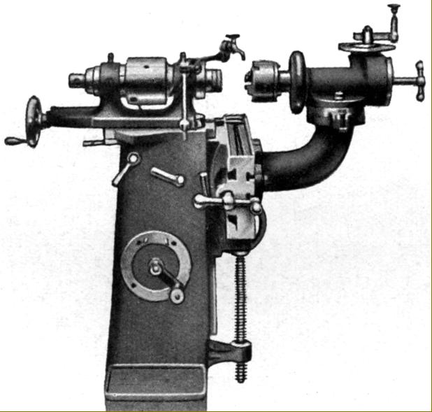
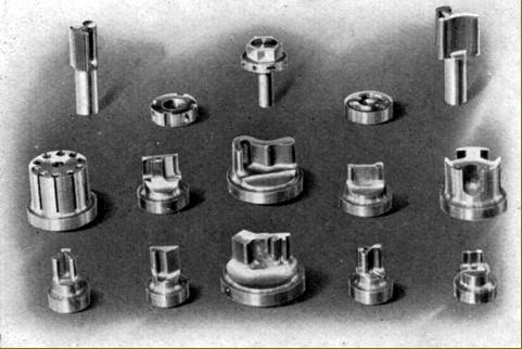
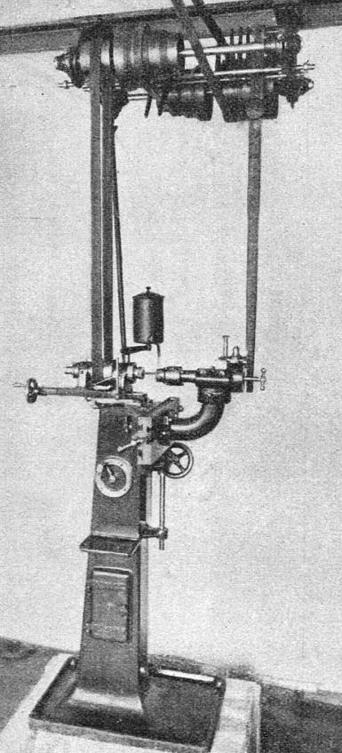
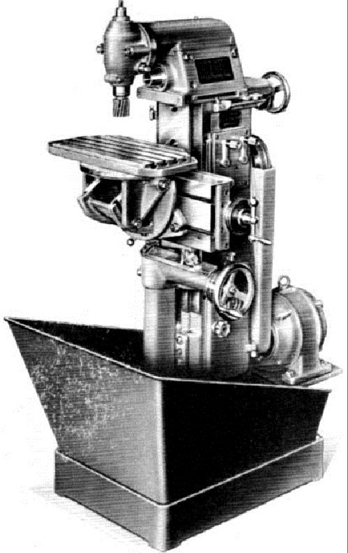
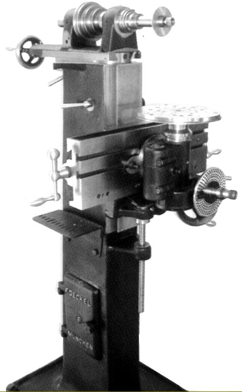
Able to be traced back to 1917, the very earliest examples of this versatile design were developed during the 1920s and advertised by the factory simply as the "FP". To distinguish these models from the later types it is now common to refer to them, unofficially, as the "Type F0". This first design had a slender main column carrying a T-slotted vertical table (on which could be mounted various pieces of dividing apparatus) with, at the top, a horizontal flat-belt drive spindle able to be moved fore and aft by a screw thread. The machine was obviously intended mainly for the production of punch dies, the various accessories (heavily promoted in the advertising literature) all lending themselves to this specialised machining process.
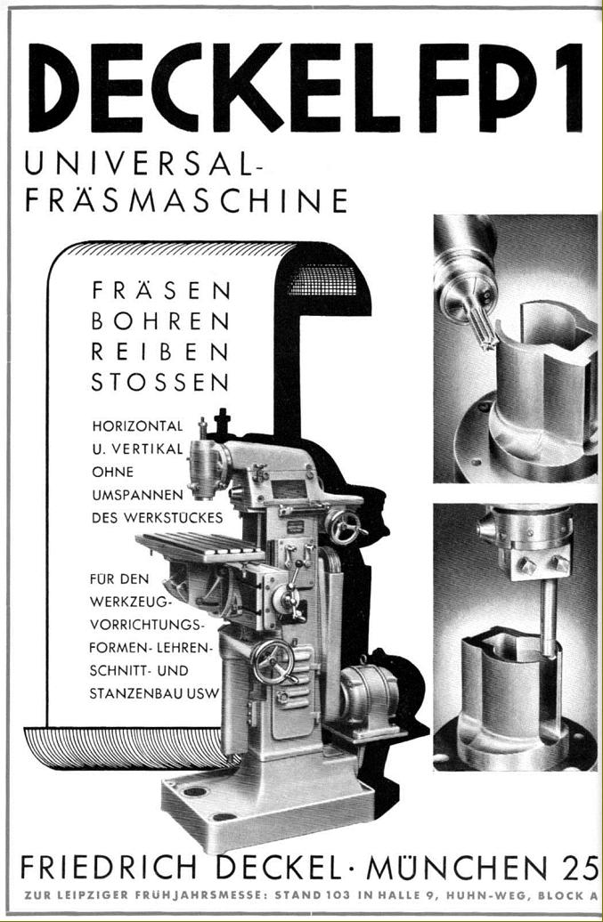
By the early 1930s the design had been considerably beefed up and, at some point between 1932 and 1934, the first one-hundred examples of the FP1 models appear to have been released - a group of machines that might be regarded as a prototypes. This first models had its table feed driven by changewheels, with a longitudinal table travel of 250 mm (later 300 mm) and the direction and engagement of the table power feed (left and right and up) operated not by the familiar Deckel "stickshift", but a little lever under the table for the longitudinal direction - and by another on the left-hand side of the machine for the up travel; the feed in the down direction was by handwheel only. By the end of WW2, in 1945, some 4100 examples of the FP1 had been manufactured and, although by the late 1930s Deckel had gained sufficient experience to manufacture other specialised machine tools for general distribution (spurred on by the German re-armament programme) camera shutters remained a mainstay of their business. As late as 1953, on the 50th anniversary of the Company, the brochure was almost entirely devoted to camera-associated products - and it was not until the late 1940s that production of machine tools expanded significantly. By the early 1950s, and with the introduction of new versions of the FP1, FP2 and other high-quality milling machines and milling accessories, a new company was formed, separate from the shutter business, to take advantage of the rapidly expanding post-WW2 industrial market. Results were impressive with, by 1965, some 50,000 examples of the FP1 having been produced, together with many thousands of different models. Other makers of the type were also active including Thiel, with their superb Type 58 and other models, and Maho, who produced a range of machines bearing a startling similarity to the FP. However, Deckel appears to have seized the lead and the FP Series (FP1, FP2 and FP3 and variants) became the most desirable types to install in toolrooms and small workshops.
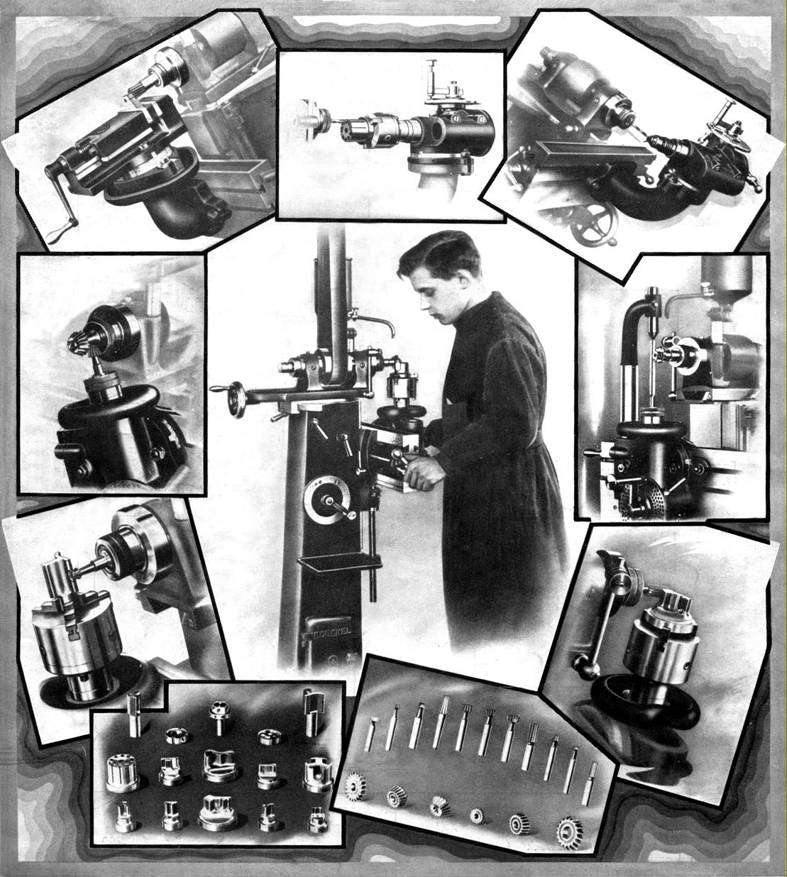
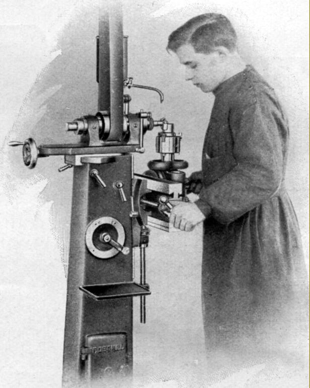
With its ingenious, adaptable and versatile design, the Deckel leant itself to solving a multitude of machining problems, the secret of the type's success being its ability to mount a number of different heads - horizontal, standard vertical, high-speed vertical and slotting - in combination with a variety of tables - plain, plain-tilting and compound swivelling. All the heads could be driven backwards and forwards across the top of the main column to provide an in-out feed, while the tables bolted to a flat, vertical T-slotted table equipped with power longitudinal and vertical feeds. By juggling the choice of heads and tables, and utilising other accessories, a skilled technician was seldom defeated in his attempts to produce the most complex of milled and drilled components - and all to a very high standard of accuracy.
*Proof of the type's success - the genus Precision Universal Milling Machine - is evident from the number of similar machines made in various countries including:
Austria:
Emco Model F3
Belgium: S.A.B.C.A. Model JRC-2
Czechoslovakia: TOS FN Models
England: Alexander "Master Toolmaker" and the Ajax "00", an import of uncertain origin.
Germany: Hahn & Kolb with their pre-WW2 Variomat model
Wilhelm Grupp Universal- Fräsmaschine Types WF1, UF 20 N/120 and others - some being sold as Mikron
Hermle Models UWF-700 and UWF-700-PH
Leinen Super Precision Micro Mill
Macmon Models M-100 & M-200 (though these were actually manufactured by Prvomajska); Maho (many models over several decades)
Ruhla
Rumag Models RW-416 and RW-416-VG
SHW (Schwabische Huttenwerke) Models UF1, UF2 and UF3
Thiel Models 58, 158 and 159
Wemas Type WMS
Italy: C.B.Ferrari Models M1R & M2R
Bandini Model FA-1/CB and badged as Fragola (agents, who also sold a version of the Spanish Meteba).
Di Palo (Early, very Deckel-FP1-like with later production including much bigger and heavier models including the Type DFF.2)
Japan: Riken Models RTM2, a copy of the FP1 and the RTM3, a copy of the Deckel FP2. These machines, made from the late 1950s until the end of the 1980s, were slowly developed and improved, are beautifully constructed and have simple, reliable electrical systems.
Poland: "Avia" and "Polamco" Models FNC25, FND-25 and FND-32 by Fabryka Obrabiarek Precyzyinych
Romanian branded for sale in the UK as the "Infratirea"?
Russia: "Stankoimport 676"
Spain: Metba Models MB-0, MB-1, MB-2, MB-3 and MB-4
Switzerland: Aciera Models F1, F2, F3, F4 and F5
Christen and Perrin Types U-O and U-1 (Perrin Frères SA, Moutier)
Hispano-Suiza S.A. Model HSS-143
Luthy
Mikron Models WF2/3S, WF3S, WF-3-DCM & WF-2/3-DCM
Perrin Type U-1
Schaublin Model 13 and Model 22
Schaffner Type 25
The former Yugoslavia: Prvomajska (in Zagreb with Models ALG-100 and ALG200)
Sinn Models MS2D & MS4D
"Comet" Model X8130, imported to the UK in the 1970s by TI Comet.
United States: Brown & Sharpe "Omniversal"
Sloane & Chace in the USA produced a miniature bench version and at least five Chinese-built models have also been made, including one from the Beijing Instrument Machine Tool Works. A number of the "clones" merely followed the general Thiel/Maho/Deckel concept whilst others, like Bandini and Christen, borrowed heavily from Deckel and even had parts that were interchangeable. Should you come across any of these makes and models all will provide "The Deckel Experience" - though you must bear in mind that spares are unlikely to be available and, being complex, finely-made mechanisms, they can be difficult and expensive to repair..
Continued below:
|
|
|
|
|
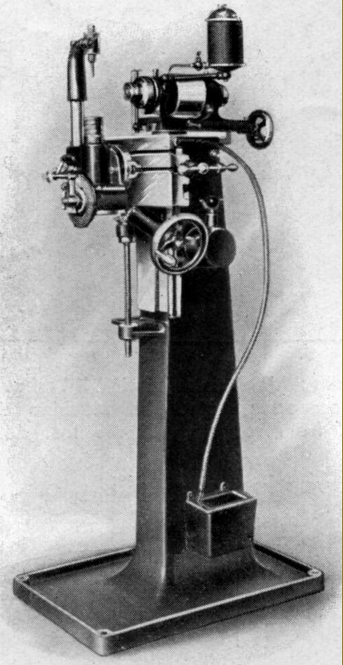
Mk. 2 FP 1 as manufactured from the mid 1950s until the early 1960s - the spindle-speed and table-feed rate changes became "all-lever" operated
Continued:
Over the years the FP1 was to be built in four main versions, each easily distinguished: the prototype of 1932-34 with non-stickshift table controls; the Mk. 1 from the mid 1930s until the late 1940s with lever-operation of spindle speeds (by the juxtaposition of two controls on the right-hand face of the column) but changewheels (inside a case on the right-hand side of the column) to vary the rate of table power feed; the Mk. 2 of the mid 1950s used levers to alter both speeds and feeds whilst the Mk. 3, introduced during the early 1960s, was fitted with more convenient and modern-looking dial controls.
General Layout
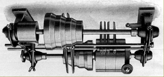
Constructed in an ingenious way, the layout of the spindle-drive system was both compact and effective: the top of the main column was machined as a slideway to carry a separate housing that doubled to mount a horizontal milling arbor or act as a base for the various heads or a horizontal milling overarm. The chrome-nickel alloy spindle was case hardened and ran in bearings that provided both excellent support and an easy means of adjustment. To solve the problem of how to drive the spindle when its housing was moved forwards and backwards (to provide lateral travel to the cutter), a long fixed gear was mounted parallel to and beneath it on the final-drive shaft and the upper gear allowed to slide along it. A word of warning for users of the English-made Alexander "Master Toolmaker" who might want to fit a Deckel head - the Alexander drive gear has a 21-degree pressure angle whilst that of the Deckel is 14.5.
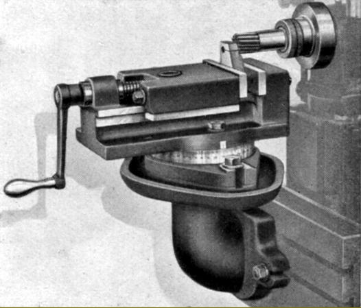
Besides normal horizontal and vertical milling operations, all models were available with a range of accessories to cover slotting, jig boring, jig grinding, spiral milling and punch milling. In respect of these operations, an important part of the machine's versatility was dictated by the multi-angle, swivelling and tilting table; with just the plain table in place, the miller remained very desirable, but it was not possible to enjoy, in full, all the FP1's ingenious capabilities.
Drive System for Head and Table
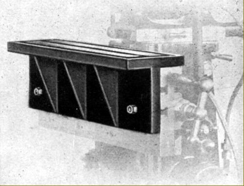
Cleverly arranged so that the table-feed rates were completely independent of spindle speeds, the drive system on the Deckel began with a two-speed, 3-phase motor mounted at the back of the machine on an easily reached, completely open and height-adjustable cast-iron platform. The table-feed gearbox was mounted inside the column, below the spindle-drive gears, and had eight speeds; used in conjunction with the two-speed motor this arrangement gave 16 rates of feed, the fastest of which, the makers suggested, was quick enough to use in place of a proper power "rapid-traverse". Whilst the rate of table feed was set by either pick-off gears or (later) two levers or a dial, on all versions except the 100 prototypes the direction of movement was controlled by an unusual (for a machine tool) ball-handled rod, rather like a car gear-change lever - what the Americans would refer to as a "stickshift". The lever controlled the movement of the main "vertical table" through eight different directions - left, right, up, down and a further four combinations where, with both horizontal and vertical feeds engaged at once, the table would move diagonally at an angle of 45 degrees. The table feed screws were all precision ground, ran though large bronze nuts and were fitted with exceptionally clear, finely engraved satin-chrome finish micrometer dials. Built-in steel rulers were provided for each axis of movement which, in combination with holders to accept dial-test indicators and gauge blocks, allowed high-precision measurements by co-ordinates to be made, independent of the feed screw readings. All table movements (around 300 mm longitudinally and 340 mm vertically) were fitted with automatic tripping stops with the upper one, to limit the table's vertical rise, fitted with micrometer adjustment. On the earliest model, to protect the table-drive mechanism against overloads, a shear pin was fitted hidden under a slip spring above the coolant pump. All gears, and their shafts, both spindle and table drive, were hardened and ground-finished. The "Y" movement was, of course made by the head, the travel being in the order of 150 mm.
Heads
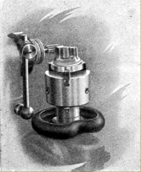
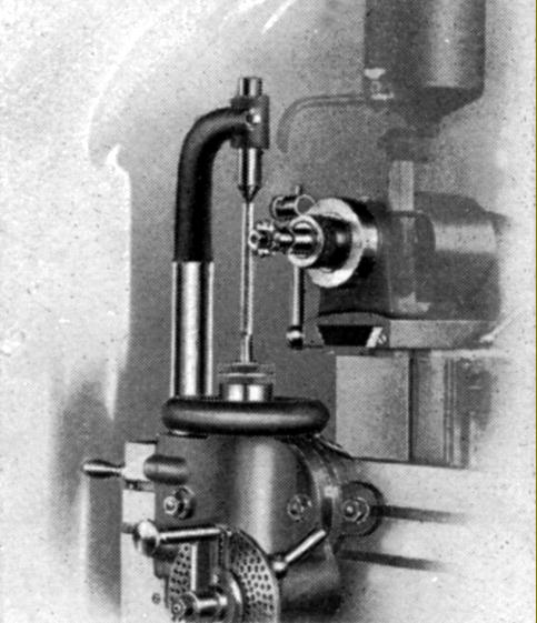
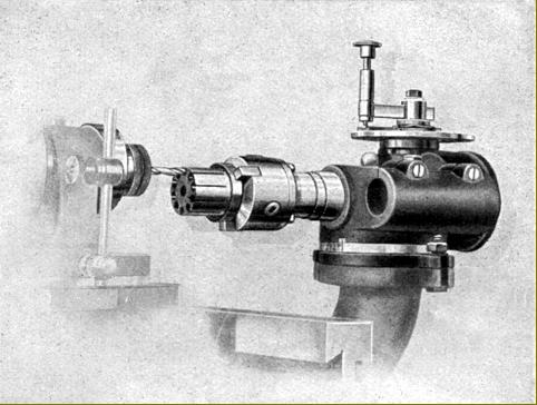
Several types of vertical head and cutter supports were available: an overarm and drop bracket to hold a horizontal milling arbor (supplied as part of the standard equipment); a Vertical Spindle Head, powered by the machine's own drive system; a High-Speed Vertical Spindle Head with its own motor; an Angular Spindle Head driven from the main motor and designed to assist with the milling of hard-to-get-at sections; a Corner Milling Spindle with its own motor and a swivelling, belt-driven end tip intended for machining internal corners and edges - and a rare Precision Boring Head from the LKB Optical Coordinate Jig Boring Machine. A simple Slotting Head was also listed.
Vertical Heads
Usually ordered with every machine as a standard accessory, the ordinary vertical head could be swivelled through 360º and was equipped with a (rather short) 2.375" (60 mm) travel quill carrying a No. 4 Morse or 40 INT nose. The maximum clearance between spindle axis and inner face of the main column was 11 inches (280 mm). Unfortunately, the head had exactly the same range of 16 speeds from 40 to 2000 rpm (or 95 to 1900 r.p.m) as the horizontal spindle - a range that (compounded by a very short lever and small knurled-edged handwheel to move the quill) limited its ability to use very small cutters. To get round the problem Deckel offered an alternative head, the "High-speed", powered by a 0.75 h.p. 3-phase motor that gave six belt-driven speeds from a low of 1900 to a maximum of 6000 r.p.m. Fitted with a 40 INT nose the head could be swivelled 45 degrees either side of central and, because the unit was self-motorised and did not require connect to the horizontal spindle-mounted drive gear, the base was able to be made extra long to provide a useful 7.875 inches of extra travel and an additional 4" of clearance from cutter centre to the column face. Unfortunately, instead of equipping the High-speed head with a long-travel quill with fine-feed control, Deckel used the same annoyingly restricted unit from the standard head - a design decision that operator charged with the delicate handling of small cutters found most frustrating.
Continued here
|
|
|
|