email: tony@lathes.co.uk
Home   Machine Tool Archive   Machine-tools Sale & Wanted
Machine Tool Manuals   Catalogues   Belts   Books  Accessories

Deckel FP1 - Page 2
Universal Precision Milling Machine

Many High-quality Deckel Publications are available - Handbooks,
Parts Manuals and Catalogues

Deckel FP1 Home Page   Deckel FP1 Page 3   Deckel FP1 Page 4

Deckel Tool & Cutter Grinders   Deckel FP2  FP1 1920s Photo Essay

Deckel FP1 Mk. 3 of the late 1950s and early 1960s with dial-change for speeds and feeds and fitted with the standard vertical milling head. This version was also copied and sold as the "Yukon"

Continued:
Angular Spindle Head
An interesting accessory, designed to machine into places that would otherwise have been impossible or very difficult to get into, the Angular Head was fitted as standard with a No. 1 Morse taper socket into which a variety of special or standard cutters could be mounted. The head could be swivelled 360 degrees about both its longitudinal and vertical axis, so allowing the tool to be set at any desired angle "in space" - not quite up to the ingenious flexibility of the system used on the (very much heavier) French-built multi-swivel Hure miller, but not far off.
Corner Milling Spindle Head
Another unit intended for use in workshops producing mould and die tooling where access to internal corners and edges was difficult. The spindle carrier assembly could be rotated through 360 degrees about its vertical axis, whilst the cutter-spindle proper could be twisted through an angle of 90 degrees. A single-lip cutter was usually used, ground specially to shape for the job required. Driven from its own 0.55 kW motor, a round drive belt, with a pair of jockey pulleys to keep it in proper contact with its pulleys, passed down the length of the column and drove the spindle head directly. Because only very small cutters, required to run at very high speeds, were employed, just two speeds of 4000 and 6000 rpm were provided.
Precision Boring Head.
Lifted from an accessory range intended for the Deckel LKB Optical Jig Borer, and offered on all sizes of FP millers, the unit for the FP1 required the use of an intermediate gearbox. The head, as might be expected, was intended for very close-tolerance boring work, especially on proper jib-boring operations in conjunction with Deckel's own optical or standard measuring systems. The spindle ran in specially made, high-precision ball bearings and had 21 speeds and 6 rates of feed. Coarse setting of the head was made by hand against a graduated scale, whilst fine adjustment was through worm gearing against gauge blocks and dial-indicator readings. The head could be tilted through 90 degrees in both directions.
Slotting Head
The swivelling slotting head is one of those accessories that can sit unused on the shelf for months, but, when needed, is an invaluable tool. Eleven ram speeds were provided ranging from 16 to 200 strokes per minute. The ram stroke, the setting of which was read from a graduated scale, could be adjusted between a travel of 0 to 80 mm (3
1/8").
Buying an FP1
There are a few general points worth considering when looking for an FP1 or similar miller. Used examples are now available very reasonably, and it's possible to invest in an example with basic equipment, in sound working order, for little more than the price of a new, but larger Far Eastern machine of indifferent quality. Unfortunately the various accessories (especially the high-speed and slotting heads and various dividing attachments) are very sought after, and command high prices; however, once acquired they are a solid investment and easily sold on when no longer required.
Being relatively complex machines, with finely made parts, dismantling requires a certain mechanical sympathy. Be suspicious of any example that shows evidence of rounded nuts, hammer blows to any of the casings or other signs of brute-force intervention - it may have been through the hands of a mechanical incompetent and suffered hidden, serious and expensive-to-put-right damage. The joy-stick lever should slide without undue force through its gate - if it has to be wrenched, something is amiss.
The FP1 was developed into the larger and mechanically very similar FP2 and FP3 Series machines with the former, in many respects, identical to the FP1 and with most of the foregoing FP1 notes applicable to it. However, the FP3 Series, made until the late years of the 20th Century, included some rather different, specialised versions and none of the FP1 and FP2 accessories able to fit..


Above and below: sections through the column-mounted gearbox of the Mk. 1 Deckel FP1

Table feed direction-control lever. Note the large table-feed micrometer dials.
Table feed direction on the FP1 was set by an unusual (for a machine tool) ball-ended rod, rather like a car gear-change lever; this controlled the movement of the main "vertical table" through eight different directions - left, right, up, down and a further four combinations where, with both horizontal and vertical feeds engaged at once,  the table would move diagonally at an angle of 45 degrees.
The feed gearbox was mounted inside the column, below the spindle drive gears and had eight speeds; used in conjunction with the two-speed motor this gave 16 rates of feed, the fastest of which, the makers suggest, was quick enough to used in place of a power "rapid-traverse". All the gears were made from hardened steel and slid on hardened and ground steel shafts.
Table movements were around 300 mm longitudinally and 340 mm vertically with the "Y" (in-and-out) movement made by the head - the travel being in the order of 150 mm.

Left: three built-in steel rulers were provided that, in combination with holders to accept dial-test indicators and gauge blocks (shown in place, left) allowed high-precision measurements by co-ordinates to be made, independent of the feed screw readings.

Above: the drive system was arranged so that the table feed rates were completely independent of the spindle speeds and only affected by the switching of the two-speed 3-phase motor.
The motor, mounted on the back of the machine on an exposed platform, can easily be changed. However, unless one can find a suitably powerful and priced 2-speed single-phase unit, it would be far better to consider using a phase converter, and retaining the original electrics.
16 spindle speeds were provided, in geometric progression, from 40 to 2000 rpm. Selection was by a knob on the right-hand face of the main body.


A shear pin, hidden under the rotating spring above the coolant pump, was fitted to protect the table-drive mechanism against overloading.

Left: Mk. 3 controls. The top dial changed the spindle speeds - the lower dial the rate of table feed.

Stops were provided for automatic tripping on all table movements. The upper stop, to limit the table's vertical rise, was fitted with a micrometer adjustment.

FP1 with an overarm for Horizontal Milling
Several types of vertical head and supports were available to mount on the top of the Deckel FP1: a standard
overarm and drop bracket to hold a horizontal milling arbor; a standard Vertical Spindle Head, powered by the machine's own drive system with the same 16 speeds as the horizontal spindle from 40 to 2000 rpm; a High-Speed Vertical Spindle Head with its own motor and a speed range from 1900 to 6000 rpm; an Angular Spindle Head driven from the main motor and designed to assist with the milling of hard-to-get-at sections; a Corner Milling Spindle with its own motor and swivelling belt-driven end tip intended for machining internal corners and edges and a rare Precision Boring Head, fitted by means of an intermediate drive gearbox, and originally developed for the LKB Optical Coordinate Jig Boring Machine. A simple Slotting Head was also available;
For the Standard and Angular Spindle heads the drive was picked up from a long gear on the machine's horizontal shaft from where it was transmitted through a pair of spiral-bevel gears to the cutter head.
Whilst the angular head could be rotated through 360 degrees the standard vertical head was restricted to 45º in each direction from central--though unlike the former it was equipped with a 2
3/8" travel quill. All the heads could be wound forwards and backwards on their seating aided by both a very a large zeroing micrometer dial and finely engraved ruler. 

Standard Vertical Head - driven from internal gearing by the main motor. A short-travel, spring-loaded quill was fitted to help with light drilling and tapping operations. The in-and-out movement was around 150 mm

The High-Speed Vertical Spindle Head carried a 0.75 h.p. 3-phase motor and had the same No. 4 Morse or (depending on year of manufacture), 40 International nose fitting as the standard unit. Six spindle speeds were provided, from a low of 1900 to a maximum of 6000 rpm. Because it had a self-contained motor, and did not rely on the usual column-mounted drive gear, the base of the attachment was made extra long to provide, in comparison to the standard head, a very useful  77/8" additional movement on its slide - and an extra 4" of clearance from the centre of its cutter to the column face. The head could be swivelled 45 degrees either side of central. Unfortunately the head lacked a fine-feed mechanism to the quill, an omission that any operator charged with the delicate handling of tiny, high-speed cutters would have regretted.

The Angular Spindle Head was an interesting accessory, designed to  machine into places that would otherwise be impossible or very difficult to get at with conventional tooling. The head carried a No. 1 Morse taper socket into which a variety of special or standard cutters could be mounted. Because the head was able to be swivelled 360 degrees about its longitudinal axis, and was mounted on a 360 degree swivel vertical axis, the cutting tool could be set at any desired angle "in space" - not quite up to the ingenious flexibility of the (much more heavily built) French multi-swivel Hure system, but not far off.

Corner Milling  Spindle Head. This unit was designed for the accurate machining of internal corners and edges in places where access was difficult. Generally a single-lip cutter was employed, ground to the shape required for the job. The unit was driven from its own 0.55 kW motor through a round belt running over 2-step pulleys that gave speeds of 4000 and 6000 rpm. The belt passed down the length of the column and drove the spindle head directly with a pair of jockey pulleys keeping it in proper contact (in the picture the belt can just be seen emerging from the column housing). 
The spindle carrier assembly could be rotated through 360 degrees about its vertical axis (the graduations can been seen around the housing) whilst the cutter spindle proper could be twisted through an angle of 90 degrees.

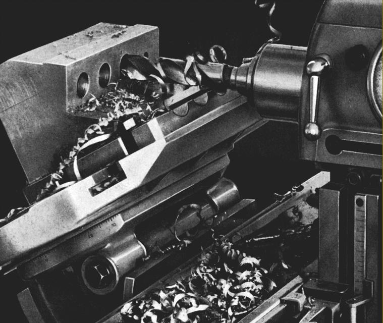
Precision Boring Head. This accessory was lifted from the LKB Optical Jig Boring machine and offered on all the FP millers - but for use on the FP1 an intermediate gearbox was required. As might be expected the head was intended for very close tolerance boring work especially when employed for proper jib-boring operations in conjunction with Deckel's own optical or standard measuring systems. The spindle ran in specially-made high-precision ball bearings and had 21 speeds and 6 rates of feed. Coarse settings of the head were made by hand against a graduated scale whilst fine adjustments were through a worm gearing against gauge blocks and dial indicator readings. The head could be tilted through 90 degrees in both directions.

Spiral Milling Attachment in place on the vertical table with the job being machined by the self-contained High-speed Vertical Head.
Although rare,, if you do  locate one you will find it a most beautifully constructed and ingenious tool capable of producing many types of spiral fluted work - milling cutters, boring tools, countersinks, straight and taper reamers, special drills etc. For work in a remote area, without access to a supply of new tooling, the spiral milling attachment would prove ideal for the manufacture of cutters for other machine tools. For spiral milling the workpiece has to be both continuously rotated and moved axially beneath the cutter, the two moments being co-ordinated in the correct mathematical sense for the job in hand. When generating spiral-fluted work that is also tapered, it must also be possible to set the work at half the included angle - rather as in generating a screw thread. If the "hand" of the workpiece flutes is the same as that of the table, both rotate in the same direction; however, if the "hand" is opposite, the direction of rotation must be "opposed" as well. Finally, it should also be possible to set the cutting tool in the direction of the flutes.  The unit fits onto the vertical table and is driven from the main table feed screw by a train of three fully-enclosed gears that connect to a power shaft passing through the base of the unit. The gears are arranged in "pick-off" form and can set so as to provide any spiral lead between 4 mm and 6400 mm, or their English equivalents.

A demonstration of the type of tapered cutter the Spiral Milling Attachment was able to produce.

A picture showing the arrangement of the unit on the vertical table

Deckel FP1 Home Page   Deckel FP1 Page 3   

Deckel FP1 Page 4
 
Deckel FP4A, FP41A, FP42A & Early NC Versions

Deckel Tool & Cutter Grinders   Deckel FP2  FP1 1920s Photo Essay

Many High-quality Deckel Publications are available
- Handbooks, Parts Manuals and Catalogues

Deckel FP1
Universal Precision Milling Machine


E-Mail Tony@lathes.co.uk 
Home    Machine Tool Archive    Machine Tools For Sale & Wanted