email: tony@lathes.co.uk
Home   Machine Tool Archive   Machine-tools Sale & Wanted
Machine Tool Manuals   Catalogues   Belts   Books  Accessories

"Smallpeice" Cromwell Precision Lathes
A data pack for the Cromwell with
Instruction Book, Parts Book and Catalogue Collection is available
Cromwell Home Page   Mk. 1 Cromwell Plain Lathe   Smallpiece Multi-cut Lathe
Rebuilt Cromwell S800   Mk. 2 Screwcutting Cromwell

Evidence for the existence of the Cromwell Company dates back to 1911, when they were engaged in the manufacture of "motor engines" at Stoney Stanton Road, just to the north of Coventry city centre; however, this is believed to have been the same company listed as having traded nearby from 1907 to 1911. By 1919, and probably under the influence of World War One conditions,  the Firm appears to have moved towards machine-tool production with Frederick Payne, then managing director, applying for a patent, No. 150560, for A different method of engaging clasp nuts by rotary means. At this time Cromwell was based at 133 Foleshill Road (again in the north of Coventry) and by 1929 were sharing the premises with a company called Smallpeice Ltd. - which, having been founded in 1919, had moved from their original works in Sawbridgeworth. Although there is no official record of Smallpeice buying Cromwell, some sort of tie-up seems to have occurred for, from this point on, the fortunes of the two concerns appear to have been linked. Smallpeice was owned by the redoubtable and gentlemanly Mr. Smallpeice and, by 1936, under directors Mr. F.P. Price and D.P. Cosby were well established with premises in the village of Marton (near Coventry) and at Mile Lane, near Coventry city centre, that they shared with Martonair Ltd., a maker of pneumatic chucks. Martonair was listed in trade directories as producing Multi-tool lathes and small grinding machines: Represented in all countries for lathes by Alfred Herbert, and in Japan and India only for Grinding Machines by Alfred Herbert.
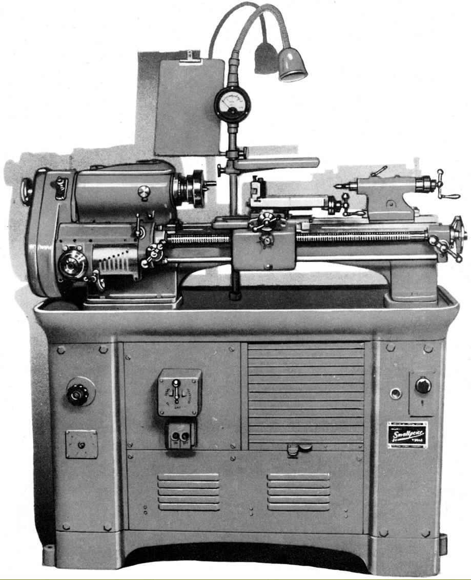
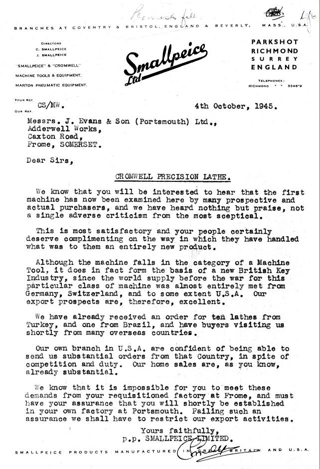
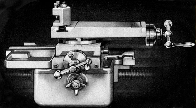
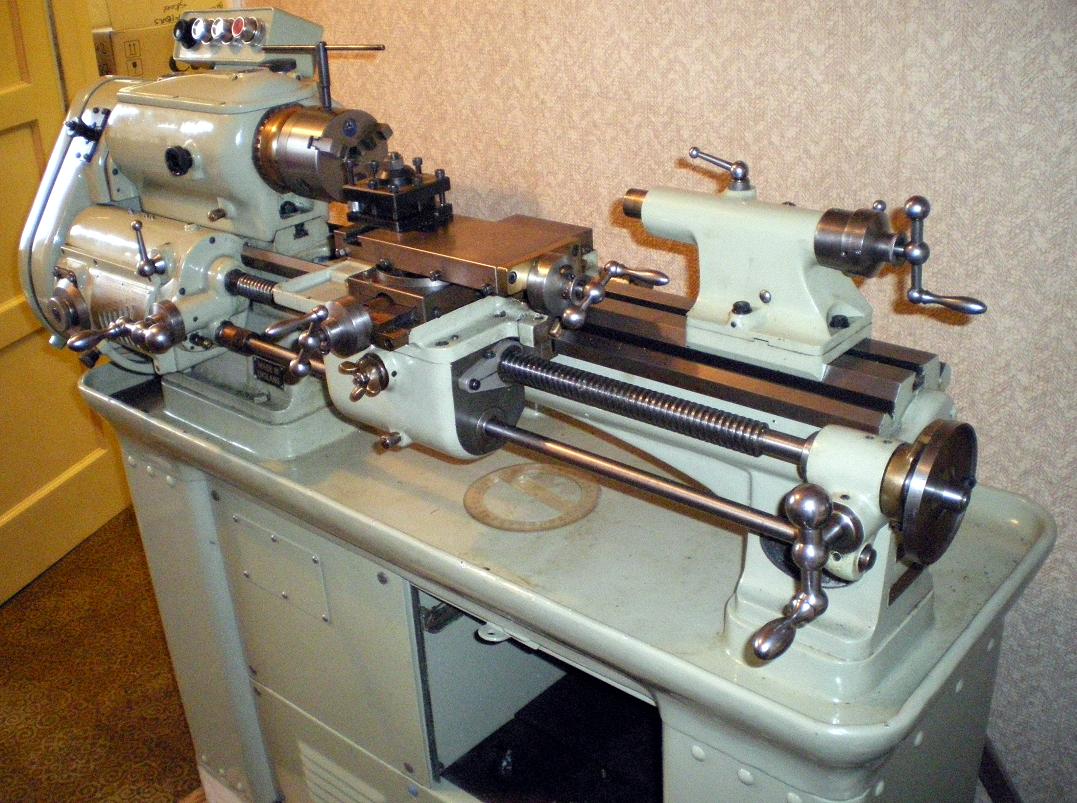
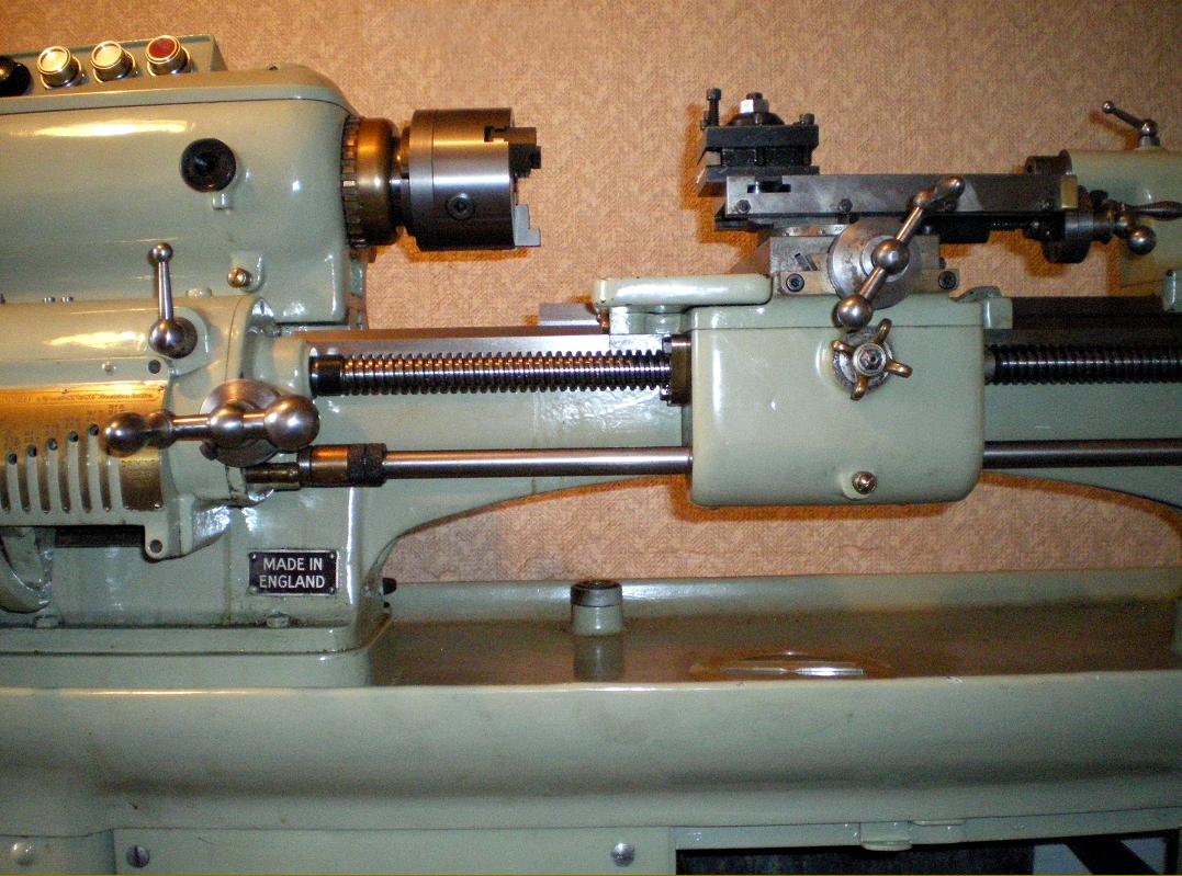
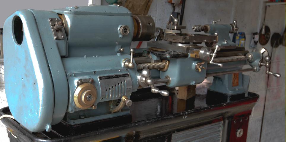
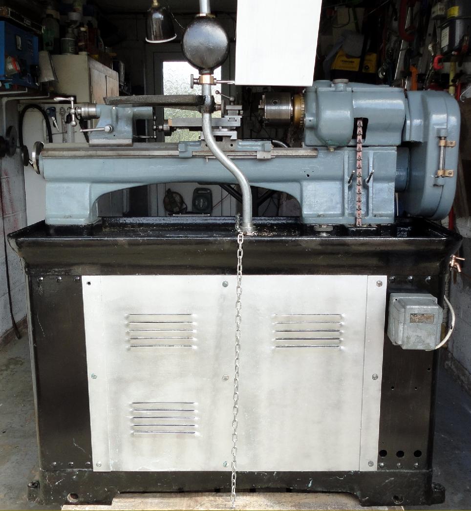
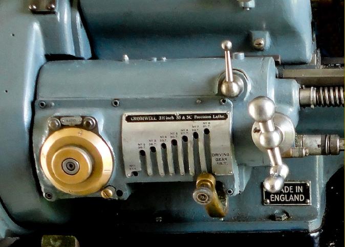
Dating from the mid-1930s, the earliest Cromwell lathe yet discovered is a precision plain-turning type of 3.5-inch centre height, mounted on a massive cast-iron stand and complete with an equally impressive built-on overhead flat-belt drive system. Elements of this lathe - the design of the carriage, cross and top slides and tailstock - were carried over to the complex backgeared and screwcutting Mk. 2 (which was also produced in a plain-turning version) and then to the more highly developed S.800 (in effect a Mk. 3) featured on this page  In the 1930s Smallpeice also began production of an interesting and useful "Multi-cut" production lathe of American origin from the
Reid Brother's Company of Massachusetts. In November 1940 the Luftwaffe flattened most of central Coventry, including Smallpeice's Mile Lane Coventry works, forcing a move to an unlikely location, a former dance hall in Parkshot, Richmond, Surrey (by good fortune or thoughtful planning, Mr. Smallpeice had moved his stock of engineering drawing from the works to his boat shed, where they escaped the inferno). Although Martonair were eventually to build a new factory in Feltham, the Cromwell/Smallpiece S800 (whether due to war-time problems or by a deliberate decision) was built under sub-contract by J. Evans & Son of Portsmouth. Established in Portsmouth in 1920, Evans had their factory commandeered by the Admiralty during the war and were banished to Frome - where they stayed until late in 1945. Naturally enough, during the conflict, their engineering skills were turned to war work, including undercarriages for both Halifax bombers and Horsa Mk. 2 invasion gliders, bomb cradles and numerous other smaller aircraft items. It is likely that Evans obtained the Smallpeice work through tender, their managing director writing in December 1944: ….to compete for the production of the Smallpeice lathe we must be careful that our work and the work produced are competitive. This does not necessarily mean low rates. A good quantity of work for a high rate is usually cheaper than a low quantity of work for a low rate. Having received the first lathe built by Evans - in October 1945 - Smallpeice wrote to Evans (on notepaper headed "Smallpeice Ltd, branches at Coventry and Bristol England, and Beverly Mass USA"): We have already received orders for ten lathes from Turkey, and one from Brazil, and have buyers visiting us shortly from many overseas countries. Our own branch in the USA are confident of being able to send us substantial orders from that country, in spite of competition and duty and also stating that production of this type of lathe ....does, in fact, form the basis of a new British Key Industry, since the world supply before the war for this particular class of machine was almost entirely met from Germany, Switzerland and to some extent USA.* Our export prospects are therefore excellent.
As part of the export drive (an essential component of post war UK industrial rebuilding), a Cromwell is known to have been exhibited at the June 1946 Paris Machine Tool Exhibition. Surviving minutes of Evans' board meetings give no indication that the Smallpeice design was made by anyone other than themselves - though, of course, all the earlier lathes would have been made by Cromwell Engineering in Coventry - with production ending after the factory's destruction. It is known that the first S800 was constructed during July 1945, in Frome, but at the end of that year Evans was able to repossess their original works in Goldsmith Lane in Portsmouth and start production in earnest. However, although surviving accounts show that by July 1947 a Cromwell lathe was worth £450 to Evans - the price of a decent family house - even at that figure they were struggling to make a profit. To keep the factory busy - and more profitable - Evans expanded into other fields including such mundane areas as vehicle repairs and the manufacture of machines for making brushes and waxed cartons. Smallpeice had also planned to produce vertical and horizontal milling machines and a grinding machine, although the only mention found of them so far is just and over-stamped brochure.
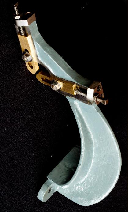
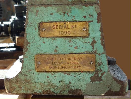
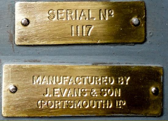
Lathe stands were made at the Highland Road works and the lathes at Goldsmith Avenue (the main Evans' works). The stands appear to have been numbered sequentially (can you find yours?) while the lathes were stamped in a series that included all other Evans' products.
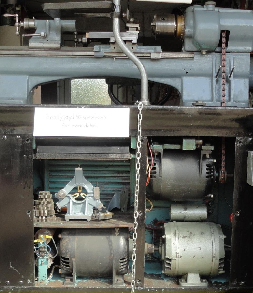
Despite careful design and high-quality materials, the first lathes were not perfect and one of the selling dealers, Herberts - the large machine-tool manufacturers and agents - provided valuable feed-back to the factory. They suggested, amongst other things, that the drive pulleys could not handle sufficient power, the micro-switch to stop the saddle was in the wrong position (this fitting was later abandoned) and vibration from the ball-bearings motors could be cured by the use of plain-bearing Brooks units. They were also critical of the headstock belt tensioning arrangements, asking for improvements to the system so that the action of the knob actually tightened the belt instead of just lowering the motor. Other notes gleaned from contemporary correspondence show that customers were pestering Alfred Herbert for delivery of the established and very successful Hardinge precision toolroom lathes (especially the new HLV), presumably due to their experience of Hardinge products during the war. However, with the HLV in very short supply (and expensive) Herbert must have seen the potential for a home-grown competitor. However, Hardinge were not sitting back, but busy consolidating their position in this segment*; they expanded production of the HLV in England, steadily developed the machine through a number of small but significant changes with the result that it became the most sought-after small toolroom-class lathe - and the company's most popular product by far.
A flavour of the hard times in 1940s Britain might be gauged from the fact that in February 1947 the company were struggling with not only the usual post-war material shortages, but also from difficulties with build time - each lathe taking 950 hours to complete against a target of 700. In the company records are many cryptic messages confirming these problems, for example:
The Anglo Iranian lathe was invoiced in January (1947) although it has not yet gone. However, after their new Sheffield-made Snow grinder was installed, production times for the bed were not only shortened but, perhaps more importantly, more examples passed inspection without the need for time-consuming rectification. By April 1947 a total of 90 lathes had been delivered and by May this had risen to 102; unfortunately, towards the end of that year, the sales were tapering off and it's possible that pent-up demand had been largely satisfied. It took until September 1951 for the 227th lathe to be delivered, yet the company were still confident of further orders and undertook to extend production past the planned 300 to 350. Numbers constructed may be summarised as follows: 61 during 1946; 111 during 1947; 47 during 1948 with the remainder (obviously built in small batches) talking until 1955: By 1956 the S800 had been dropped from the catalogues - although records show that in November of that year a few unsold examples still remained in stock. During the post-war years something like 100 Multicut lathes were also built, together with a batch of 20-inch shapers to be sold under the Herbert brand.
At some point in the mid-1950s a company called Lancing Tools bought up the manufacturing rights to the S800, so Evans made the very last of the batch for them, rather than for Smallpeice. In 1958 Lancing then sought to buy the Cromwell trademark, together with all other tangible assets relating to the lathe. However, on the last day of December 1958 it is recorded that it was Evans, not Smallpiece who had rejected Lancing's offer of £4000. Thus, it would seem that that Evans had already bought the rights to Smallpeice - who by then had bigger fish to fry, being consumed with their interest in Martonair, by then a substantial business (that had grown out of their initial involvement with pneumatic chucks and production tooling) and still using the factory in Marton..
Continued below:

Mk. 3 Smallpeice Cromwell Precision lathe Type S.800
Note the revolution counter built into the lamp-support tube.

Continued:
Machine Details:
A very expensive, fine-quality machine designed for use in toolrooms and by instrument, gauge and optical-equipment makers, the post-war "Cromwell S.S. & S.C. 3.5" x 19" Super-Precision Model S.800" was first advertised in 1946 at £448, though few can have been available for delivery (at the time a Myford ML7, of the same capacity, was just £46, and attracted a waiting list that stretched to over 12 months. As might be expected, the attention to detail and use of fine-quality materials was exemplary - with even the 6 felt wiper housings on the saddle, the vernier scale on the leadscrew handwheel, the end brackets on the cross and top slides the hinges on the changewheel cover being made from bronze (on the Mk. 2 even the reversing switch facia panel was in this material - an astonishing waste of resources and added expense for the customer. Although the lathe and its stand weighed nearly half a ton, almost four times as much as the Myford, it was not designed for heavy-duty roughing work, that would have been done on another lathe and the work transferred to the Cromwell for accurate finishing; even so, in amateur hands, when pressed into general service duty, it will easily outperform any equivalent-sized machine in this respect. The lathe began life in the 1930s as the now very rare Mk. 1 flat-belt drive model, developed through the backgeared and screwcutting (and plain-turning) Mk. 2 to become (with considerable modifications) the well known and highly-respected Mk. 3 (S.800) with electronic variable-speed drive. The lathe was further developed as a 4-inch centre height "Series 2" with a mechanical variable-speed drive system by the continental manufacturer Prym; in contrast to the often-encountered S.800 3 this is a very rare model - and few can have been produced.
Headstock
The spindle of the S.800 was driven by a "Ward-Leonard" electrical system that comprised a 3-phase motor attached to a DC generator that in turn supplied current for a DC motor controlled by an early form of electronic variable-speed drive. The result was a step-less speed range, with dynamic braking, from 20 to 2000 r.p.m. as well as a geared range from 3 to 290 r.p.m. The operator controlled the spindle speed with a single black plastic handwheel positioned conveniently to hand on the front face of the stand's headstock-end plinth. Today, unfortunately, very few Cromwells are found with the original electrical system intact for, over the years, as the original components failed, many were fitted with conventional V-belt drive countershaft units. However, now that miniature computer-controlled phase inverters and similar devices are available, it is possible, by using just a single 3-phase motor in place of the DC motor, to completely restore (and possibly improve) all the functionality and wonderful simplicity of the original speed-control system. The final drive to the spindle was by a flat belt, the tension of which could be adjusted quickly and easily by screwing in a large, knurled-edge knob that rose through the chip tray immediately behind the headstock.
Made from nitride-hardened steel the headstock spindle was ground and lapped to provide a perfect surface finish; it ran in continuously adjustable, precision plain-bearings of the taper-split type, with internal cones at either end that engaged with cones on the adjusting nuts; this method of construction ensuring that the bearings were held firmly outwards against the taper bore of their housings. Sealed in its own compartment against the ingress of oil and dirt from the backgear assembly the flat-belt spindle pulley ran in its own, independent ball-bearing sleeve - and so removed from the main spindle all effects of belt pull and belt-transmitted vibration. While other manufacturers of precision lathes boasted of finishing the spindle bearings when the headstock had been bolted to the lathe bed, Evans reversed the process. They finished the tapered bearing seats first then used those as a datum to mount the headstock on a jig (which replicated the bed mounting) before finally machining the headstock casting base relative to the spindle line. The inside of the spindle had a 20 mm parallel section and a short 15-degree taper (30 degrees total included angle) - both ground in after the lathe was assembled. The collet used was a Hardinge Type 4500, a now obsolete model but one that may well have been replicated under some other number by Schaublin, Royal or Crawford. Hardinge, in the USA, confirms that their records show supplying collets to Cromwell in the mid-1930s. To enhance rigidity, chucks and other spindle fittings were mounted on a combination of a screw, taper and large-diameter spigot face. The headstock was backgeared with operation by a wheel on the front of the headstock (this disengaged a small gear on the spindle from a surrounding internally geared sleeve) together with a second rotary control on top of the headstock by which means the bronze drive gears were slid into mesh with the spindle-mounted steel gears.
Continued below:

Cromwell (S.800) Lathe with rear cover removed showing, on the bottom shelf, the 3-phase motor and DC generator and, at the top, the DC motor that drove the spindle by a flat belt.
Continued:

Bed
Copied from an arrangement in use on the contemporary (and competing) Schaublin 102-VM, the bed had three ways: a V-form at front and back for the saddle and another of typically precision bench lathe design* in the centre with a flat top and bevelled edges used to locate headstock and tailstock. The casting was subjected to considerable attention by skilled craftsmen being first rough machined then seasoned for several months to relieve stresses, machined accurately, hardened and finally ground and hand-finished. Its inspection was rigorous; the maximum permissible error, in convex only, was 0.0002" over the entire length of the ways and the makers claimed to be able to take two beds at random from stock, mount them face to face, and find a variation in flatness of only 0.0001" over their entire length.
Slides and Power Feeds
Surprisingly, although the compound slide rest worked very smoothly (especially the 5 inches of top slide movement) its feed screws and micrometer dials were only of modest diameter - although the latter was given a vernier scale engraved into the fixed inner section of the dial assembly. Typical of Cromwell ingenuity, the top slide was of unusual design for, while a normal V-edge was used, with a gib strip, instead of the base casting being flanged for the upper casting to run on, the roof of the upper casting was employed instead - a most unusual arrangement. The bolt-on end flange of each slide as also in bronze, an expensive way of providing a bearing for the feed screw to run through. Power cross feed was fitted as standard, operated by a separate shaft beneath the leadscrew that drove a bronze worm and wheel - the latter with a cone clutch formed in its centre into which was pushed, by a bronze wing nut on the face of the apron, a steel gear that meshed with a gear on the cross-feed screw. Unfortunately, if the faces of the clutch became polished, it could be almost impossible to apply enough pressure on the small wing nut to keep the drive engaged. 
Screwcutting
With the advent of the S800 Cromwell designers dropped the convoluted and expensive-to-produce screwcutting and feeds arrangement of the Mk. 2 and chose instead a straightforward, quick-change gearbox drive. Careful thought was given to the design of the box: it was laid out as a magazine type, to offer the same wide range of threads and quick operation of a conventional unit, yet eliminate the usual open slots in the front (through which dirt could enter) and also allow its tumbler gear to run in an oil bath. A rotary dial selected four sliding and surfacing speeds that could be engaged instantly for every position of the main tumbler - while a lever (just inboard of the point where the leadscrew entered the box) could be used to switch immediately from fine to coarse feed. Complete with English, BA and metric sections the screwcutting chart was engraved into a thick brass plate mounted on the inside face of the changewheel compartment's hinge-open cover. Instead of the usual split-nut to engage the leadscrew, the apron carried two 'solid' nuts, spaced well apart and adjustable relative to one another, as in a micrometer, to compensate for wear and to eliminate backlash. Despite the simplification of the screwcutting and feeds arrangements Cromwell just could not help adding an interesting and well-engineered complication: because the coarse-pitch leadscrew was in permanent engagement with the carriage - and would have been difficult to turn with the usual handle at the tailstock end - two handles were provided,, one at each end of the leadscrew with each working through easily-turned worm-and-wheel gearing. A large 0.0001" vernier scale dial was fitted at the tailstock end of the leadscrew, to assist in the accurate turning of shoulders and other lengths, and a smaller dial on the headstock-end handwheel. The leadscrew (1-inch diameter by 4 t.p.i. or 6 mm pitch Acme-form) was known to hold true to within 0.0005" over twelve inches - and, if necessary, a lathe could be provided with a N.P.L. certificate guaranteeing the accuracy of the screw to within 0.004" over its full length of thirty inches - however, the normal accuracy over this length, as shown on factory test certificates (where each lathe was individually checked against a N.P.L. master leadscrew) was actually better, at just 0.002". A separate power shaft was fitted to drive the standard-fit power cross feed.
Stands
Using cast-iron for its chip tray and floor base, the cabinet stand was fitted with heavy-gauge, plate-steel ends and sheet-steel side panels; as the slatted tool cabinet cover on the right-hand side was lifted, a light came on to illuminate the inside; even the tool tray itself was not allowed to escape the designer's attention to detail: each spanner and key slotted into its own milled and named recess and, as the tray was withdrawn, it dropped down at an angle to present its contents to the operator.
Supplied with each lathe were a dividing plate and indexing plunger; a headstock collet draw-tube with a centre formed on the end of a solid collet; drive plate, tailstock centre, adjustable saddle stop, a light unit, tool tray and tools, a single-tool tool post and "
left and right-hand tool rests".
Rolls Royce bought numbers of these machines for their tools rooms, and it is not unusual to find their label, or that of NCR (National Cash Registers), Metal Box or various aircraft companies adorning Cromwell lathes.
If you have, or know of, any type of early Cromwell lathes, or have access to Cromwell or Smallpiece literature, the author would be pleased to hear from you.
*
Precision lathes as made by (amongst others): Levin, Bottum, American Watch Tool Company, B.C.Ames, Bottum, Hjorth, Potter, Pratt & Whitney, Rivett, Wade, Waltham Machine Works, WadePratt & Whitney, Rivett, Cataract, Hardinge, Elgin, Remington, Sloan & Chace, W.H.Nichols, Crystal Lakes and (though now very rare) Frederick Pearce, Crystal Lake, Ballou & Whitcombe, Sawyer Watch Tool Co., Engineering Appliances, Fenn-Sadler, "Cosa Corporation of New York" and UND..

A letter from Smallpeice after they inspected the first lathe produced by Evans.

Compound slide rest detail. The bronze wing nut on the apron engaged the power cross feed.

Cut-away section of screwcutting gearbox.

Section through the headstock

A particularly fine example of the Cromwell S.S. & S.C. 3.5" x 19" Super-Precision Model S.800

Pull-out collet and tool tray

The drive pulley was contained within its own compartment sealed against oil and dirt. In this picture the headstock spindle is locked for direct drive with the internally-geared sleeve (moved by the bronze lever) in position over the smaller spindle gear.

The sleeve slid back to expose the smaller spindle gear

Backgear engaged

One of few examples to have survived with the revolution counter intact

Distinctive travelling steady


email: tony@lathes.co.uk
Home   Machine Tool Archive   Machine-tools Sale & Wanted
Machine Tool Manuals   Catalogues   Belts   Books  Accessories

"Smallpeice" Cromwell Precision Lathes
A data pack for the Cromwell with
Instruction Book, Parts Book and Catalogue Collection is available
Cromwell Home Page   Mk. 1 Cromwell Plain Lathe   Smallpiece Multi-cut Lathe
Rebuilt Cromwell S800   Mk. 2 Screwcutting Cromwell