|
Machine Tool Manuals Catalogues Belts Books Accessories 21, 25 & 28-inch Lathes 30, 32, 36 & 42-inch Lathes Carriage & Slides Accessories Factory Headstock, Bearings & Friction Backgear 1940s & 1950s Metalmaster Coarse Screwcutting Attachment A Maker's Instruction Book, Parts List, Sectional-diagram Books and catalogs are available for Bradford lathes |
||
|
|
||
|
|
||
|
|
||

|
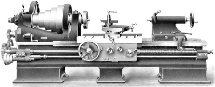
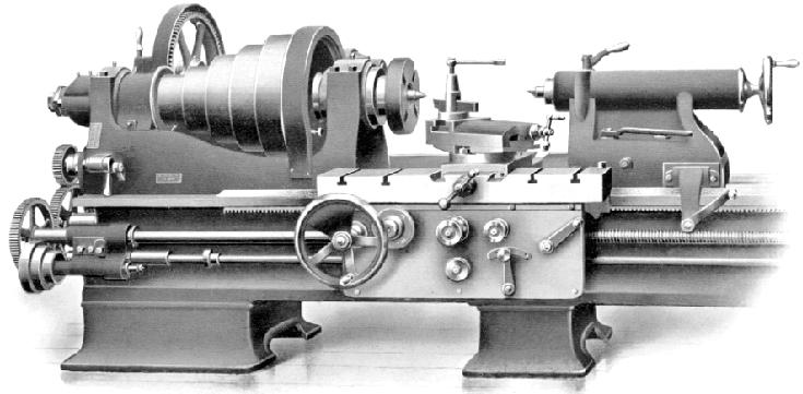
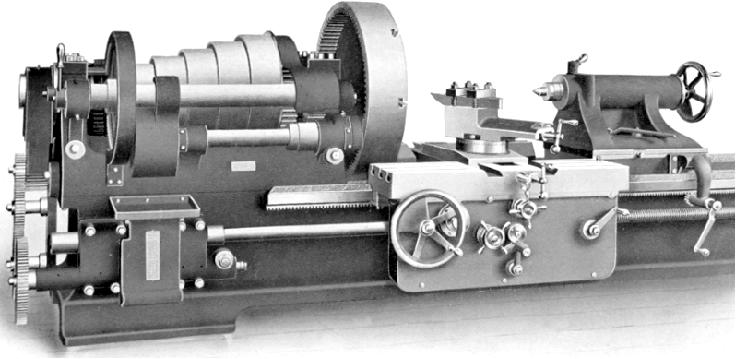
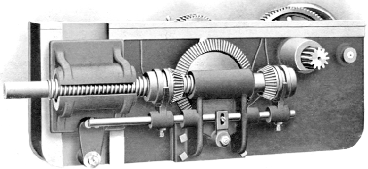
A genuine "triple-geared" headstock spindle with a conventional "backgear" mounted in front of the spindle and a second reduction taken from a point a little way along from its larger gear; a third reduction in ratio was created by the final drive to a gear cut on the inside rim of the faceplate. Some makers, using advertising "puff", claimed "triple-backgear" status for their lathes which had only two gear-driven reductions - their argument being that lathes with no backgear at all were often referred to as "single-geared", hence a conventional "single" installation of a backgear should be called double-geared, and one with two backgears awarded the status of "triple"….. |
||
|
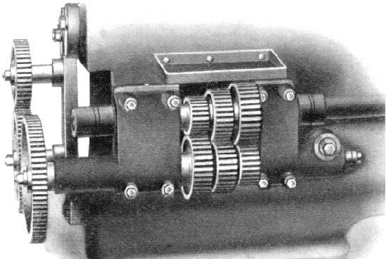
A simple "translation" gearbox to give three screwcutting ratios - and three sliding and surfacing speeds from one setting of the changewheels. |
||
|
An instant reverse was fitted to the power feed by using two independent pinions, one at each side of the crown wheel. A slot in the leadscrew (there was, despite their size, no separate power shaft on the two largest lathes) drove each and as either could be swung into engagement with the crown wheel it could be made to rotate in either direction. Separate clutches engaged either power sliding (along the bed) or power surfacing (across it). |
||
|
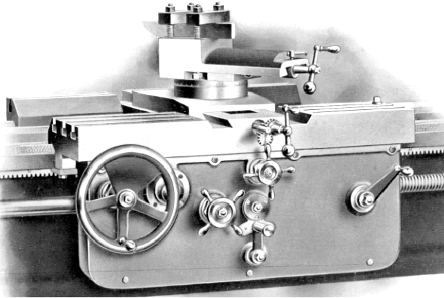
Apron front showing the balance-weighted carriage-traverse hand wheel, a capstan-handled clutch engagement knob for power sliding and, above it to the right, a slightly smaller capstan-handled knob to engage power surfacing. The three-position quadrant lever was used to select neutral and power sliding and surfacing feeds and, on the far right, the leadscrew clasp-nut engagement handle. |
||
|
Machine Tool Manuals Catalogues Belts Books Accessories 21, 25 & 28-inch Lathes 30, 32, 36 & 42-inch Lathes Carriage & Slides Accessories Factory Headstock, Bearings & Friction Backgear 1950s Metalmaster 1941 Metalmaster Coarse Screwcutting Attachment A Maker's Instruction Book, Parts List, Sectional-diagram Books and catalogs are available for Bradford lathes |
||