 |
|
|
|
|
|
|
|
|
|
|
|
|
|
|
|
|
|
|
|
|
|
|
|
|
|
|
|
|
|
|
|
|
|
|
|
|
|
|
|
|
|
|
|
|
|
|
|
|
|
|
|
|
|
|
|
|
|
|
|
|
|
|
|
|
|
|
|
|
|
|
|
|
Although now best known for their 1930s to 1950s "Metalmaster" lathes the Bradford Mill Company was founded as long ago as 1840 on Eighth and Evans Streets in Cincinnati, Ohio by James Bradford (as a partnership) to manufacture flour milling machinery. However, by 1890 their extensive factory, then at 657-671 Evans Street, was producing nothing but good quality centre (engine) lathes of all kinds and the Company's became a corporation, changing its name to "The Bradford Machine Tool Company".
The second World War saw the erection, in 1943, of a new plant to manufacture four-ton, six-wheel drive truck axles for the Government; this building was used from 1946 to make a new range of electric grinders, buffers, polishers and portable electric hand tools - a range which gradually absorbed most of Bradford's production capacity, the lathe line in the 1950s being reduced to a single model, the "Metalmaster", built with swings of 14, 16 and 18 inches.
If any reader had advertising material or information relating to any year of Bradford production, the author would be very pleased to hear from them. Also sought: a clear picture of the screwcutting plate from a "Metalmaster" of any year..
|
|
|
|
|
|
|
|
 |
|
|
|
|
|
|
|
|
|
All Bradford lathes, from the largest 42-inch to the smallest 14-inch were fitted with good quality components, carefully assembled and guaranteed to "bore to within 0.002 of an inch in 24 inches". Details included oil channels machined (instead of being "chipped in" by hand) on their own specially-modified lathes fitted with a type of coarse-screwcutting attachments; all small gears were cut from steel bar - not cast - and all studs were claimed to be in hardened and ground tool steel.
The headstocks were unusual in carrying five pulleys, giving (with backgear) ten spindle speeds - a useful improvement of the 6 or 8 usually offered on this class of lathe; the largest lathes, with "triple-backgear" had 15 speeds. The leadscrews were made in-house (not all lathe makers were sufficiently well equipped or skilled to manufacture leadscrews) and made to a "correct master" with matched half-nuts for the best possible accuracy; the carriage-drive rack was cut from one length of steel - up to 12 feet in length - instead of being assembled from cheaply-bought odd lengths as often found on the lathes from less-particular companies.
Screwcutting could be to either English or metric standards - in the latter case with a metric leadscrew, not just a set of conversion gears - with a full set of changewheels proved with each lathe to, "admit of the chasing of all threads commonly in use." The "tumble-reverse" gears - the means by which the leadscrew could be made to rotate in either direction, or not at all - was housed within the headstock walls underneath the spindle and controlled by a small handle on the headstock face. A separate power shaft for sliding and surfacing feeds was fitted, driven from a gear on the leadscrew contained within a small covered housing built integrally with the headstock-end leadscrew-support bracket. Strangely, the 36 and 42-inch lathes lacked the power shaft, but their feed gearbox was modified to house a nest of six gears, three of which could be slid into position to provide three rates of feed for each setting of the changewheels. An additional refinement, on all but the two largest lathes, was the provision of a 3-speed fine-feed belt drive to the power shaft. On lathes up to 18 inch swing the lower of the two pulleys was mounted on a swinging bracket, fitted with an extension formed into a hand hold; it would appear that this provided a simple means for the operator to engage and disengage the feed by holding the belt in tension manually; the final drive from the pulley was taken through a pair of gears to an input shaft which continued underneath the power shaft for a short distance before culminating in a gear. To select the feed from leadscrew or belt drive, a sliding sleeve on the power shaft was fitted with a single groove which engaged with thin rims formed as an extensions to the leadscrew and belt-drive gears; as the sleeve was pushed in or pulled out the appropriate gear was caused to mesh with a single gear on the end of the powershaft. Amazingly, the useful belt-drive facility was not mentioned in any of the maker's literature.
|
|
|
|
|
|
|
|
|
|
 |
|
|
|
|
|
|
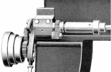
Detail from the (non-screwcutting) stud lathe showing the arrangement of the belt-drive feed to the powershaft.
|
|
|
|
|
|
|
|
 |
|
|
|
|
|
|
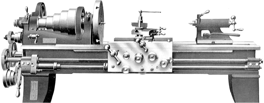
14-inch Standard Lathe with 6-foot long bed.
With a true swing over the bed of 147/8 inches and a between-centres capacity of 37 inches, the Standard lathe rested on a pair of simple cast-iron legs and was supplied without an oil pan or guards for the changewheels. Able to be ordered with a bed of 6, 8, 10 or 12 feet long, the latter had a capacity of 74 inches between centres.
The 5-step headstock pulley - with steps 23/8" wide for 21/4" wide belt - had diameters of 3.5", 4.625", 6.5", 8.375" and 9.5" and was driven by a slightly larger pulley with steps of 4.125", 5.25", 7.125", 9" and 10.125"; the 5-step drive pulley was attached to a 10-inch diameter countershaft pulley intended to be run at 145 revolutions per minute; the backgear reduction ratio was 9.6 to 1 With this configuration the 10 speeds spanned approximately 6.5 rpm to 420 rpm.
The No. 2 Morse taper spindle carried a 2-inch diameter nose threaded 7 t.p.i and was bored through to clear 13/64". It ran in a front bearing 3.75 inches long and 2.4375 inches in diameter while the rear bearing, 2.75" inches long and 1.875 inches in diameter was considerably smaller.
The leadscrew was threaded 6 t.p.i and, with the changewheels supplied as standard, could cut threads from 40 to 60 - including a 111/2 t.p.i pipe thread.
Equipped with a 6-foot bed the lathe weighed 1600 lbs with 75 lbs being added for every extra foot of length.
|
|
|
|
|
|
|
|
|
|
|
|
|
|
|
|
|
 |
|
|
|
|
|
|
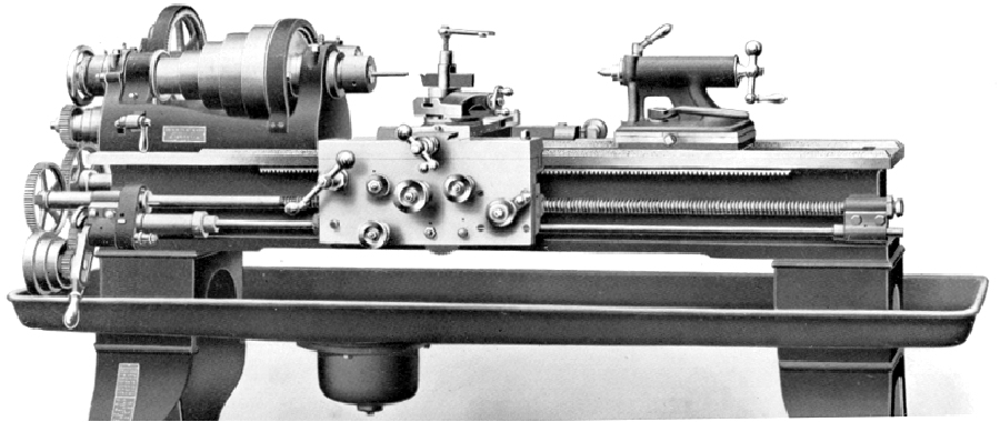
14-inch Toolroom lathe.
The toolroom version of the 14-inch was of the same general dimensions as the standard machine but was supplied as standard with an oil pan equipped stand, taper-turning attachment and a draw-in collet assembly with seven collets from 1/8" to 1/2" together with a spindle nose piece. The larger versions of the toolroom lathe were similarly equipped but, at extra cost, could be supplied with collets having a larger through-capacity.
|
|
|
|
|
|
|
|
|
|
|
 |
|
|
|
|
|
|
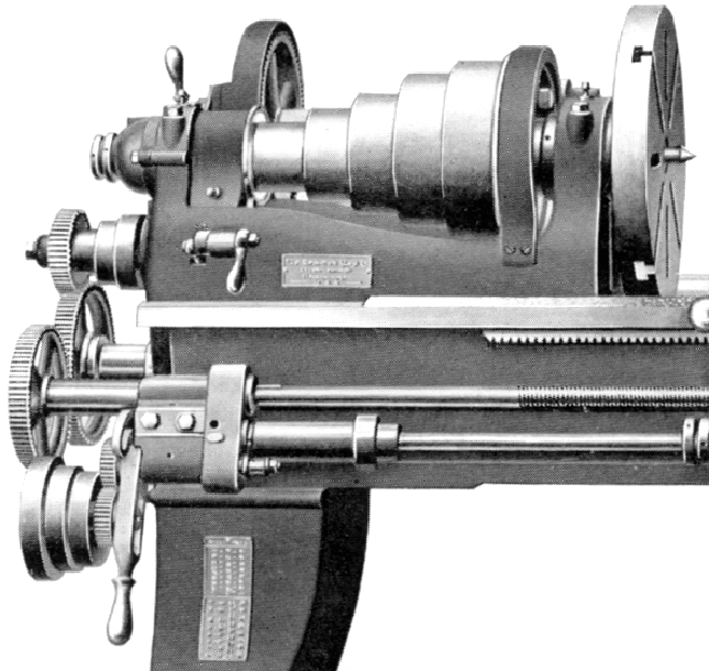
Headstock-end detail showing the standard-fit T-slotted faceplate and fine-feed belt drive to the powershaft driven through two gears on a swinging quadrant.
|
|
|
|
|
|
|
|
|
|
|
 |
|
|
|
|
|
|
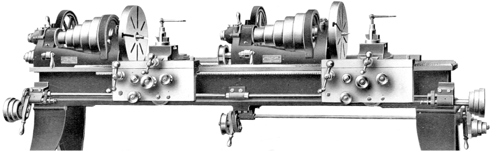
14-inch Duplex Facing Lathe.
Designed for production use on facing and short turning jobs - and intended to be used by a single operator.
To assist the operator - and cut down on the time spent racing from one end of the machine to the other - a third power-feed control lever was mounted in the middle of the bed and driven from a duplicate set of pulleys at the tailstock end of the main powershaft.
|
|
|
|
|
|
|
|
|
|
|
|
|
|
|
|
|
|