 |
|
|
|
|
|
|
|
|
|
|
|
|
|
|
|
|
|
|
|
|
|
|
|
|
|
|
|
|
|
|
|
|
|
|
|
|
|
|
|
|
|
|
|
|
|
|
|
|
|
|
|
|
|
|
|
|
|
|
|
|
|
|
|
|
|
|
|
|
|
|
|
|
|
|
|
|
|
|
|
|
|
|
|
|
|
|
|
|
|
|
|
|
|
|
|
|
|
|
|
|
|
|
|
|
|
|
|
|
|
|
|
|
|
|
|
|
|
|
|
|
|
|
|
|
|
|
|
|
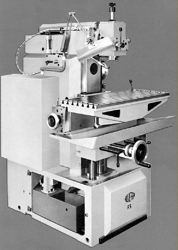
Aciera F Series precision milling machines were eventually to be built in several versions: the first, in the 1930s was the F11 followed, in 1943, by the quite different and super-precision F12; after this, in the late 1940s, came the long-lived and very popular F1 and (rare) F2 - with both designed for clock, watch and instrument work. Larger machines were the more general-purpose F3, F4 and F5 models. In addition, by the early 1970s, a limited number of production variants were also being manufactured designated F1N, F1h, F1NC, F3EC and F5NC.
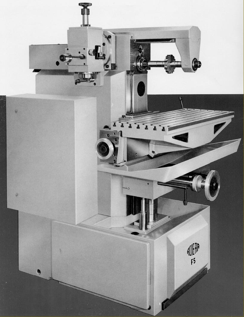
Built as a more robust, greater-capacity version of the F4, the F5 was made only in a late, angular style, there being no earlier version with the "rounded" appearance of the types from the 1950s. It followed the usual design parameters for this specialised machine, as produced by a number of other makers, notably in Europe, but also elsewhere*. The aim was to provide a versatile, adaptable model that could be pressed into service to solve as wide a variety of machining problems as possible. In order to achieve this, the top of the main column was fitted with a dovetail slide able to accept a number of different heads, all of which could be driven backwards and forwards by a handwheel, working through helical gears, to provide an in/out feed of some 7 inches (175 mm). Heads included one to drive a horizontal arbor; a novel swing-aside vertical driven from the horizontal spindle (and available with or without a quill feed); a simple high-speed vertical; a standard high-speed vertical; one dedicated to corner milling and a slotting attachment. By combining the heads with a choice of five T-slotted tables - vertical, plain horizontal, lowered horizontal, compound tilting and swivelling and a version of the latter with a removable top - a skilled technician was seldom defeated in his attempts to produce the most complex of milled and drilled components, and all to a very high standard of accuracy. Unlike similar machines from other manufacturers that had a large T-slotted vertical table permanently mounted in place of a conventional knee, on the Aciera a wide, flat vertical surface was provided (the makers referred to it as the "apron") with the tables and other fittings located by being hooked over hand-scraped V-ways at the top and bottom. At the lower edge, to lock the assembly in place, a pair of bolts passed through the casting to tighten a loose gib block. Although this system might appear to have been less versatile than a bolt-on, T-slotted assembly, it did ensure that everything lined up perfectly and required no remedial action (tapping the table and snugging up nuts) to get level. In addition, to obtain extra capacity, the table could be positioned at any point on the apron - and to within an accuracy of 0.001" when moved from extreme left to extreme right.
The F5 was built on an almost square, heavy cast-iron base 730 mm wide and 1030 mm deep that held a 4 h.p. 1400 r.p.m. motor powering a variable-speed drive system by expanding and contracting pulleys. After the belt stage the drive passed to a speed-change gearbox containing hardened and ground gears, running on ball-bearing shafts and lubricated by splash, and from there to an upper shaft from where it could be picked up by the horizontal milling spindle unit, direct-drive vertical head (non-high-speed type) or the slotting head. Because the machine was relatively large, some essential control functions - hand elevation of the table, rapid-feed selector and spindle stop/start buttons - were duplicated on the front of the machine and on the right-hand face of the column.
Continued below:
|
|
|
|
|
|
|
|
 |
|
|
|
|
|
|
Continued:
Heads and Head Fittings
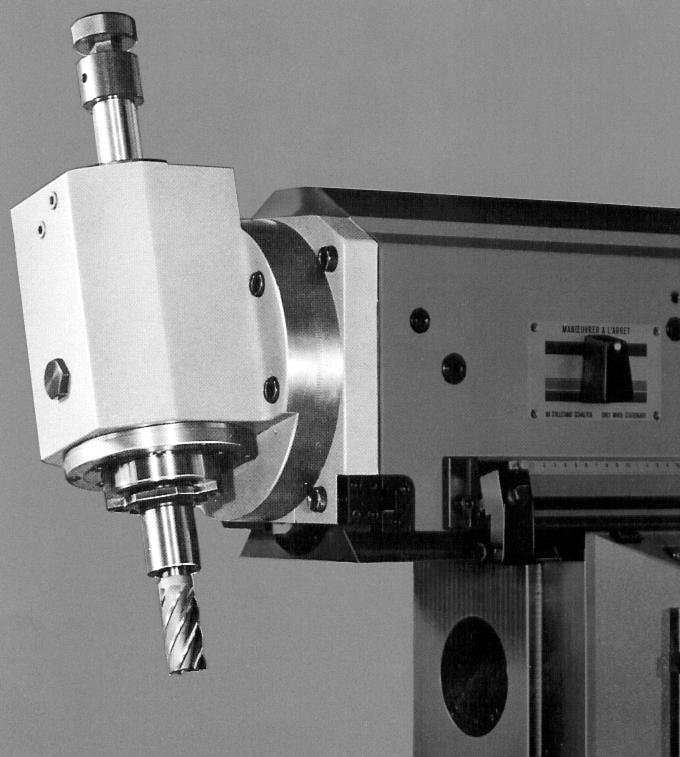
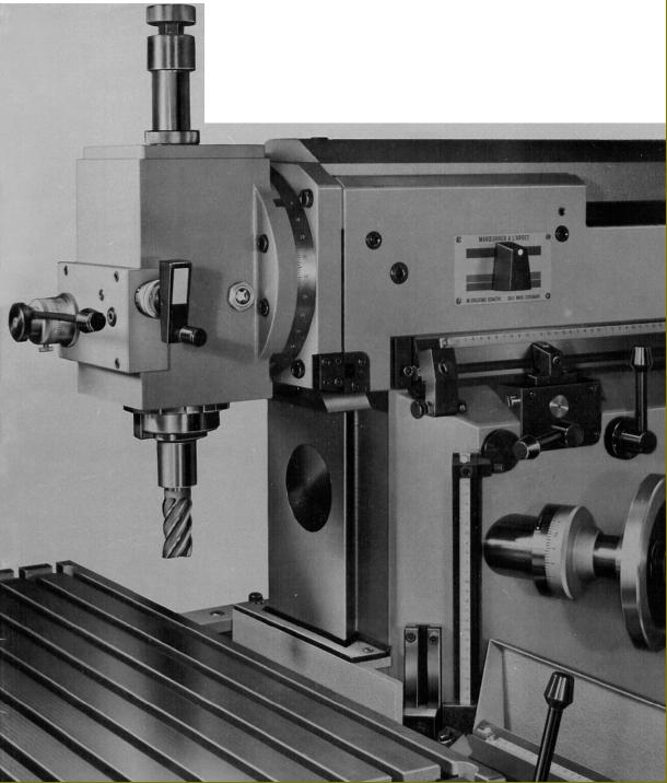
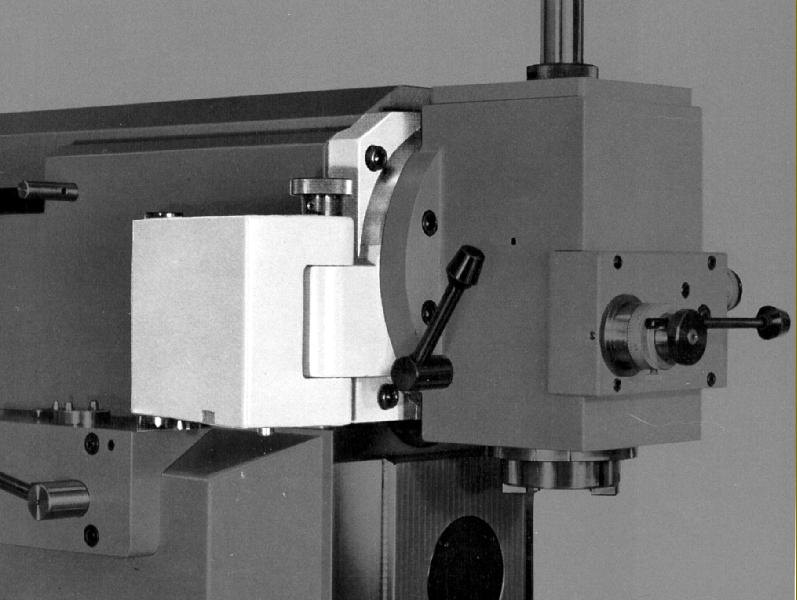
Hardened and ground, the horizontal spindle had a speed range from 50 to 2000 r.p.m. while the standard vertical head, which contained its own two-speed gearbox, was able to span a more useful 50 to 3400 r.p.m. Both horizontal and vertical heads employed selected, adjustable high-precision taper-roller bearings - an adjustable double-row taper roller at the front and a conical roller and thrust bearing at the rear - and were fitted as standard with a No. 40 ISO taper spindle nose, though with the no-cost option of a No. 30 ISO if desired. The direct-drive vertical head was unusual in having its end section mounted on a swing-away bracket, a design that allowed a much faster change to be made from horizontal to vertical machining. The head was available with either a fixed or a sliding quill - the latter fitted with both worm-and-wheel fine-down-feed and a quick-action lever feed for drilling. Quill travel was 2.375 inches (60 mm), the head could be inclined through 90° in either direction from vertical and the spindle axis brought to within 3.125 inches (10 mm) inches of the column's inner face or moved as far away as 15.875 inches (4300 mm). The maximum distance between the surface of the fixed angular table and spindle nose was 16.875 inches (360 mm) and the minimum 0.375 inches (10 mm). However, when the universal table was fitted, the maximum clearance was reduced to 14.125 inches (359 mm). One interesting option, fitted to the F5 vertical head only and designed to assist with the use of tungsten carbide cutters, was a 19 lb (8.5 kg) Inertia Wheel (flywheel) that clamped to the upper section of the spindle.
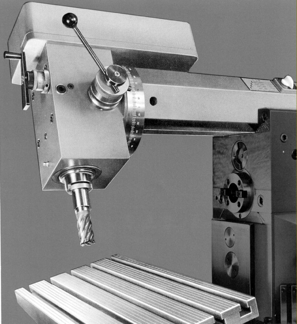
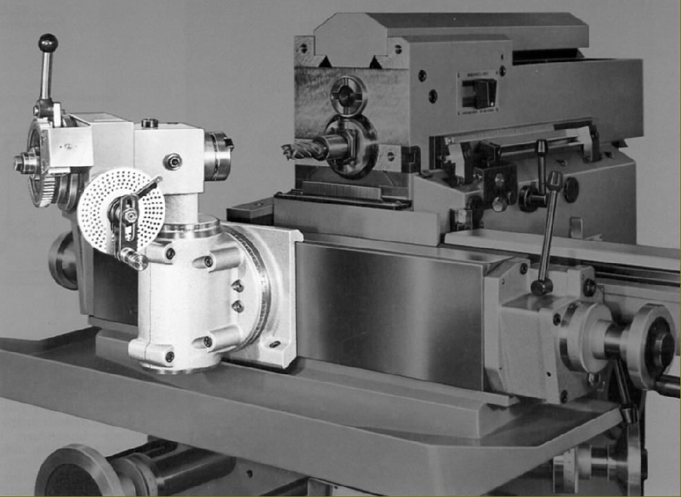
Three other independently-powered vertical heads were available, two identical to those used on the Aciera F4 and the third a special Corner-milling Attachment. The Simple High-speed Vertical Head had a 0.5 h.p. 2,800 r.p.m. motor that gave four V-belt driven speeds of 1000, 2000, 4000 and 6000 r.p.m. and a quill moved by a quick-action lever through a rather short 2.375 inches (60 mm) of travel. The spindle nose accepted double-taper ES-32 collets (or ISO30) that held cutters by friction only, there being no positive location by thread or collet chuck. A more robust unit was the High-speed Vertical Head; this used a two-speed, 1400/2800 r.p.m. 0.75 h.p. motor that provided eight speeds of 500, 700, 1000, 1400, 2000, 3000, 4000 and 6000 r.p.m. The spindle, fitted with an ISO-30-M12 or ISO-30-1/2" nose, was able to take a collet chuck, had 3.125 inches of travel and was fitted with both a quick-action lever and fine-feed handwheel. Both heads could be swivelled but, whilst the Simple Type with its smaller motor and greater clearance from the overarm could be turned through 60° in each direction, the standard version was restricted to 45° - though when advanced forwards could be swung through a full 90°. The Corner-milling Attachment was carried on the end of the horizontal milling overarm - though located on its (underside) dovetail ways - and had a 0.16 h.p. motor that provided speeds of 2000, 4000 and 6000 r.p.m. The unit could be swivelled through 360° and had a nose that could be inclined through 90° and accepted either a 4 or 6 mm collet.
Continued below:
|
|
|
|
|
|
|
|
 |
|
|
|
|
|
|
Standard vertical head and the Universal Table
|
|
|
|
|
|
|
|
|
|
|
|
|
|
|
Continued:
Tables and Table Drive
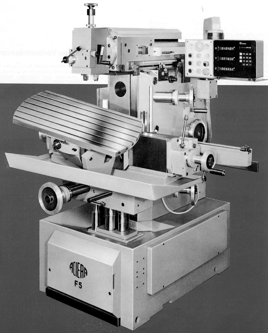
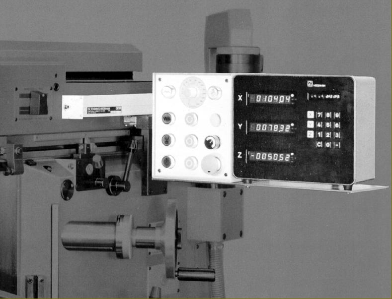
Table drive was under the control of a separate 1 h.p. motor mounted in the right-hand section of the stand and pointing downwards. The system was complex, with the motor driving a train of gears that could be used to provide "rapids" in any direction (at the rate of 59"/1500 mm per minute) or take the drive to a variable-speed system using expanding and contracting pulleys. With the addition of fixed gear ratios, a range of feeds horizontally and vertically was provided from 0.5" to 14" (10 to 360 mm) per minute. Unlike the ingenious joystick control on the competing Deckel FP1 and FP2, the Aciera used simple and conveniently positioned levers to engage the feeds, that for vertical being next to the manual-elevation handwheel and for horizontal by the longitudinal handwheel at the right-hand end of the table. Feed rates were varied by a large handwheel on the face of the stand, with the fixed-ratio gear selector control below and to its right. The table feed screws were all of large diameter, precision ground in hardened steel for the best possible accuracy and ran though large bronze nuts. To give maximum help to the operator, exceptionally large, finely engraved satin-chrome finish micrometer dials were fitted, complimented, on each axis, by built-in precision steel rulers and adjustable stops. DRO systems (digital read-outs) had been available for general use since the early 1970s and the F5 was one of the first millers to be offered one as standard equipment. Indeed, so confident were the Aciera of its superiority - a choice was offered of Bausch & Lomb "Acu-Rite"or Heidenhain 5041 types - that only a brief mention was made in the publicity literature of previous-generation technology - ground gauge blocks, dial indicators, Trav-a-Dial readers or optical measuring equipment. Horizontally table travel was 19.7" (500 mm), vertical 16.5" (420 mm) and the head could be moved in and out through 12.8" (325 mm). However, because the accessory various tables could be slid left and right along the vertical face of the "knee" for a distance of 500 mm, the total horizontal travel that could be achieved was 1000 mm.
Vital in exploiting the full versatility of the F5 was the 146 lbs (66 kg) Universal Table: with five DIN 650 12 mm wide T-slots running down its 23.5-inch (600 mm) length the 10-inch (250 mm) wide table could be pivoted left or right through 15° from central and tilted backwards or forwards through 30° from horizontal. Although a finely-engineered piece of equipment it could not, because of the numerous clamping surfaces, take heavy cuts, and patience was required in its use For ordinary work an alternative fitting, the 35.375" x 13.125" (900 mm x 350 mm) Fixed Angular Table was available. With the same number and spacing of T-slots as the Universal this 170-lb (77 kg) unit was far more rigid and able to resist the cutting forces of larger diameter cutters and faster feeds. For mounting other accessories, a 46 lb (21 kg) 15.75" x 8" Vertical Plate with eight T-slots was provided - this being especially useful when fitted with various combinations of rotary table, dividing heads and special adaptors.
Continued below:
|
|
|
|
|
|
|
|
 |
|
|
|
|
|
|
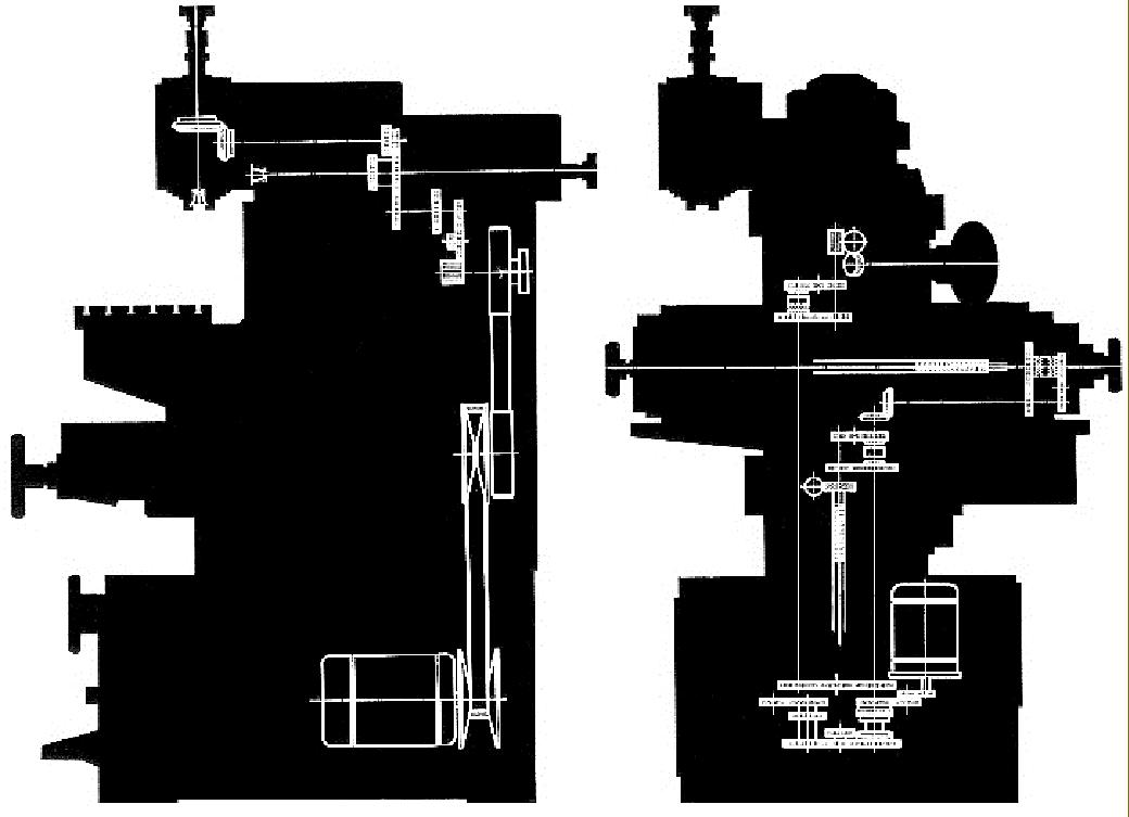
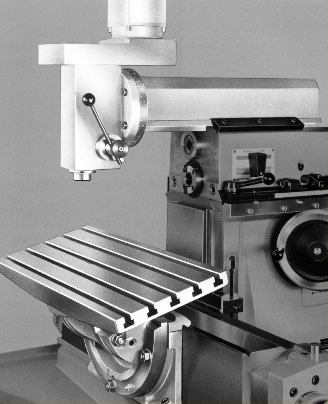
Left : table drive system Right: drive to the horizontal spindle and vertical head
|
|
|
|
|
|
|
|
|
Continued:
Accessories
A wide range of other extras was produced, for the F5, many identical to those offered for the F4 and capable of being used in combination with each other. Three versions of the 4.3125" (110 mm) centre height Universal Dividing Head were listed: the standard unit, with a graduated drum for direct dividing and indirect by a worm gear and dividing plates; a model fitted with a Direct Dividing Device where a division could be obtained by a single movement of a lever that simultaneously unlatched, selected and indexed the setting - and a further development of the latter model that included a lever-operated collet closer. All types, with the exception of the lever version with its ISO-40 spindle and Schaublin Type 20 collets, had the option of four nose fittings: ISO-30-M12, ISO-30-1/2", ISO-40-M16 or ISO-40-5/8". Two tailstocks could be used with the dividing head: a plain type with a No. 2 Morse taper, a fine-feed travel of 0.75" and one that, using the same basic components, was fitted with a 22 mm travel quill and a quick-clamping mechanism.
A more complex dividing head was also available - the Universal Inclinable. With the same range of nose fittings as the standard head, this 4-inch (100 mm) centre height version had a body that could be rotated from horizontal to vertical. A 24-hole indexing plate was fitted as part of the standard specification, as was a set of three indexing plates. Another option was a power-feed unit that provided a spiral indexing facility (used in conjunction with the Universal Milling Head). This employed a train of gears contained in a cast box with machined-in T-slots with a drive taken from the table's horizontal feed shaft - the gear set comprising wheels of: 24, 24, 28, 32, 40, 44, 48, 56, 64, 72, 86 and 100t.
For simple dividing the Indexing Fixture was available; this was, in effect, an angle plate, able to be mounted horizontally or vertically, fitted with a 3-jaw chuck on a rotary base drilled with a set of twelve indexing holes.
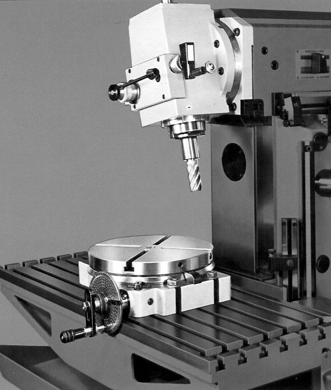
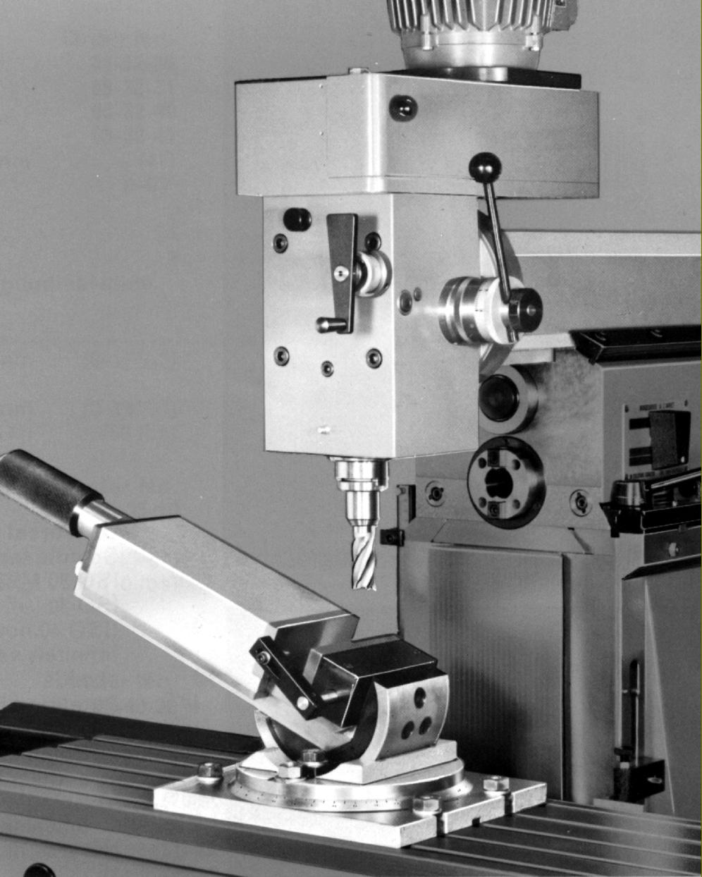
Several rotary tables were available; the most common was the Universa1, an 11-inch (280 mm) diameter, 4-inch (100 mm) thick unit fitted with a dividing plate (three were provided) and four radial T-slots to DIN 650 and 12 mm wide. The worm drive provided a rotation of 4° for each revolution of the handle.
A very much more complex and versatile model was the Co-ordinate Rotary Table: this beautifully-made and heavy unit (176 lbs/80 kg) consisted of a rotary table, with worm drive plus and indexing-plate facility, mounted on an angle plate for direct fixing to the F4's vertical table. Integral with the rotary element was a compound slide rest that carried a 11.75" x 8.625" (300 x 220 mm) table with three T-slots. X and Y feeds were both 4.75" (120 mm) a travel that, although limited, was sufficient to allow the precise rectangular and polar positioning of small workpieces in relation to the spindle axis.
For small jobs that needed the facility to be rotated and offset in just one direction, the Co-ordinate attachment was available. Built on a 2.375-inch (60 mm) travel slideway, the 4.375-inch (110 mm) rotary table had indexing through worm-and-wheel control only.
When buying a complex, finely-made machine such as the F5 mechanical condition is paramount; no spares are available and any replacement parts have to be made as one-offs. Although today a basic but serviceable late-model example can be purchased in the UK for an amount roughly equal to a month's average salary - a tiny fraction of its original price - but a near-perfect, lightly-used example complete with a good number of the more desirable accessories might command four-times as much.
*Proof of the type's success - the genus Precision Universal Milling Machine - is evident from the number of similar machines made in various countries including:
Austria:
Emco Model F3
Belgium: S.A.B.C.A. Model JRC-2
Czechoslovakia: TOS FN Models
England: Alexander "Master Toolmaker" and the Ajax "00", an import of uncertain origin.
Germany: Hahn & Kolb with their pre-WW2 Variomat model
Wilhelm Grupp Universal- Fräsmaschine Type UF 20 N/120
Hermle Models UWF-700 and UWF-700-PH
Leinen Super Precision Micro Mill
Macmon Models M-100 & M-200 (though these were actually manufactured by Prvomajska); Maho (many models over several decades)
Ruhla
Rumag Models RW-416 and RW-416-VG
SHW (Schwabische Huttenwerke) Models UF1, UF2 and UF3
Thiel Models 58, 158 and 159
Wemas Type WMS
Italy: C.B.Ferrari Models M1R & M2R
Bandini Model FA-1/CB and badged as Fragola (agents, who also sold a version of the Spanish Meteba).
Japan: Riken Models RTM2 and RTM3
Poland: "Avia" and "Polamco" Models FNC25, FND-25 and FND-32 by Fabryka Obrabiarek Precyzyinych
Russia: "Stankoimport 676"
Spain: Metba Models MB-0, MB-1, MB-2, MB-3 and MB-4
Switzerland: Aciera Models F1, F2, F3, F4 and F5
Christen and Perrin Types U-O and U-1 (Perrin Frères SA, Moutier)
Hispano-Suiza S.A. Model HSS-143
Mikron Models WF2/3S, WF3S, WF-3-DCM & WF-2/3-DCM
Perrin Type U-1
Schaublin Model 13
United States: Brown & Smart Omniversal
(The former) Yugoslavia: Prvomajska (in Zagreb with Models ALG-100 and ALG200)
Sinn Models MS2D & MS4D
"Comet" Model X8130, imported to the UK in the 1970s by TI Comet.
Sloane & Chace in the USA produced a miniature bench version and at least five Chinese-built models have also been made, including one from the Beijing Instrument Machine Tool Works. A number of the "clones" merely followed the general Thiel/Maho/Deckel concept whilst others, like Bandini and Christen, borrowed heavily from Deckel and even had parts that were interchangeable. Should you come across any of these makes and models all will provide "The Deckel Experience" - though you must bear in mind that spares are unlikely to be available and, being complex, finely-made mechanisms, they can be difficult and expensive to repair..
|
|
|
|
|
|
|
|
|
|
|
|
|
|
 |
|
|
|
|
|
|
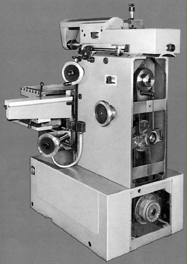
View of the variable-speed drive to the spindle
|
|
|
|
|
|
|
|
 |
|
|
|
|
|
|
The robust Fixed Angular Table
|
|
|
|
|
|
|
|
|
|
|
|
|
|
 |
|
|
|
|
|
|
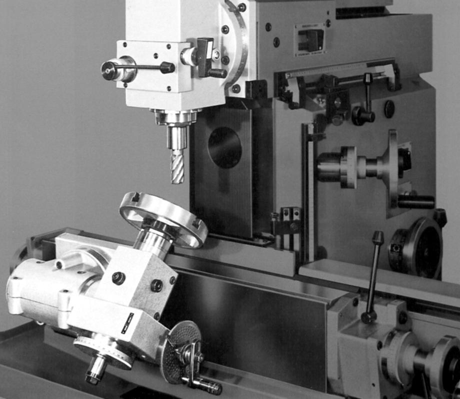
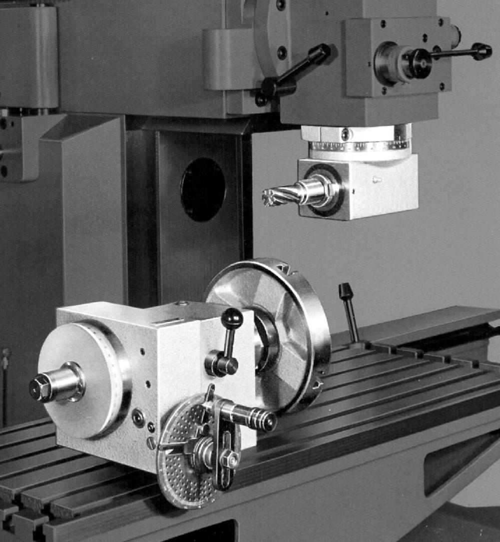
The basic rotary table and standard vertical head
|
|
|
|
|
|
|
|
 |
|
|
|
|
|
|
Standard non-quill-feed vertical head
|
|
|
|
|
|
|
|
 |
|
|
|
|
|
|
He very much more useful quill-feed head with fine and quick action feed
|
|
|
|
|
|
|
|
|
|
|
|
|
|
 |
|
|
|
|
|
|
High-speed Vertical Head; as used on the F4 and F5. This employed a two-speed, 1400/2800 r.p.m. 0.75 h.p. motor to give eight speeds of 500, 700, 1000, 1400, 2000, 3000, 4000 and 6000 r.p.m. The spindle, fitted with an ISO-30-M12 or ISO-30-1/2" nose, was able to take a collet chuck, had 3.125 inches of travel and was fitted with both a quick-action lever and fine-feed
|
|
|
|
|
|
|
|
 |
|
|
|
|
|
|
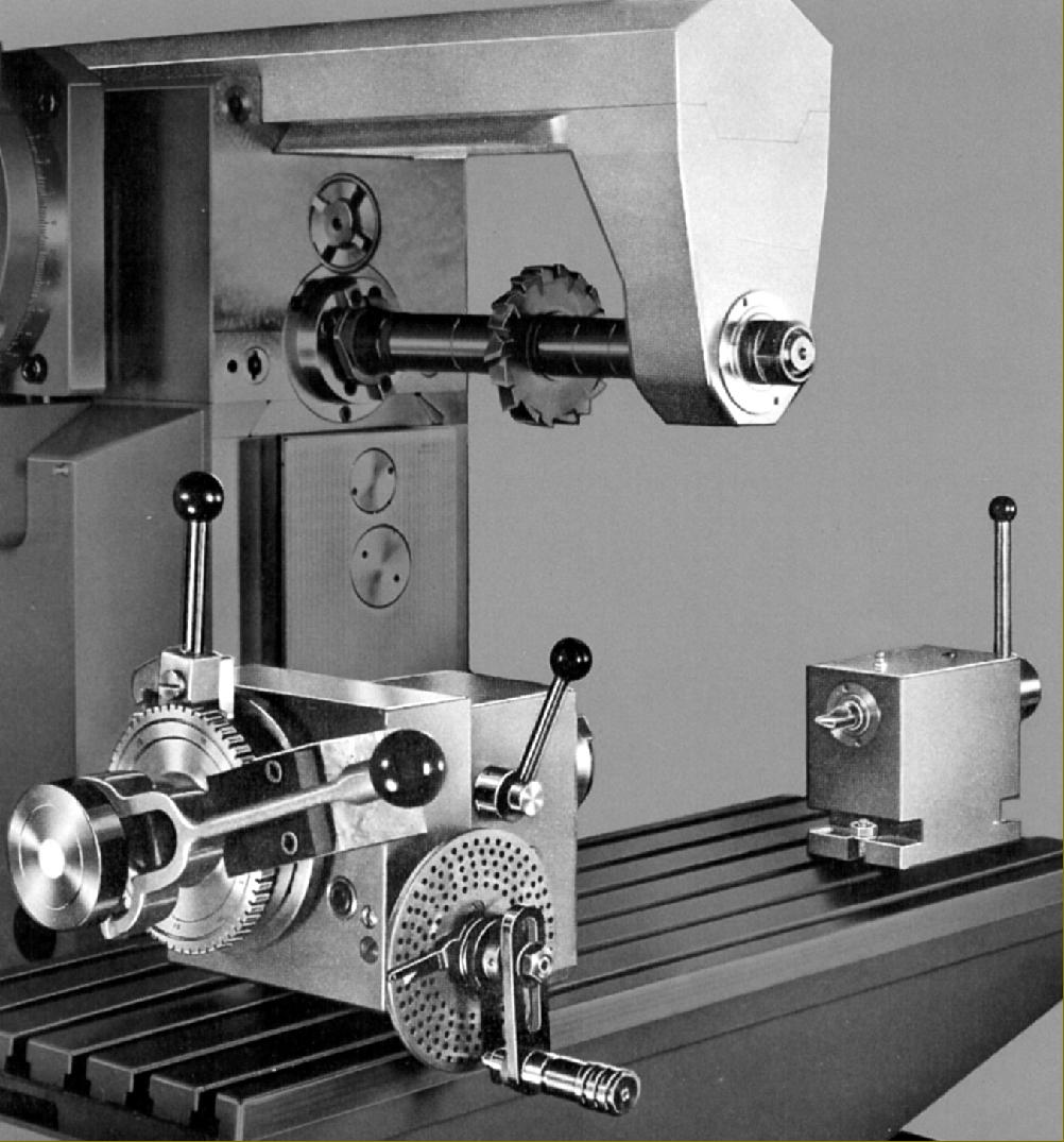
Slotting head and the 46 lb (21 kg) 15.75" x 8" Vertical Plate with eight T-slots - an especially useful item designed to carry various combinations of rotary table, dividing heads and special adaptors.
|
|
|
|
|
|
|
|
 |
|
|
|
|
|
|
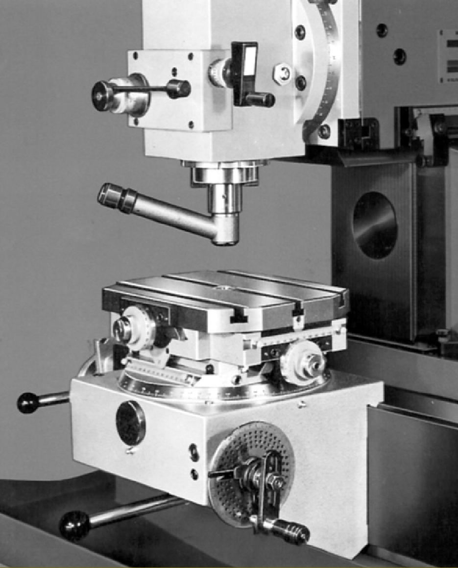
A very much more complex and versatile dividing apparatus was the Co-ordinate Rotary Table: this beautifully-made and heavy unit (176 lbs/80 kg) consisted of a rotary table, with worm drive plus and indexing-plate facility, mounted on an angle plate for direct fixing to the F5's vertical table. Integral with the rotary element was a compound slide rest that carried a 11.75" x 8.625" (300 x 220 mm) table with three T-slots. X and Y feeds were both 4.75" (120 mm) a travel that, although limited, was sufficient to allow the precise rectangular and polar positioning of small workpieces in relation to the spindle axis. Also shown is the Centering microscope.
|
|
|
|
|
|
|
|
|
|
|
|
|
|
 |
|
|
|
|
|
The Simple High-speed Vertical Head for the F4 and F5. This had a 0.5 h.p. 2,800 r.p.m. motor that gave four V-belt driven speeds of 1000, 2000, 4000 and 6000 r.p.m. and a quill moved by a quick-action lever through a rather short 2.375 inches
|
|
|
|
|
|
|
|
 |
|
|
|
|
|
 |
|
|
|
|
|
|
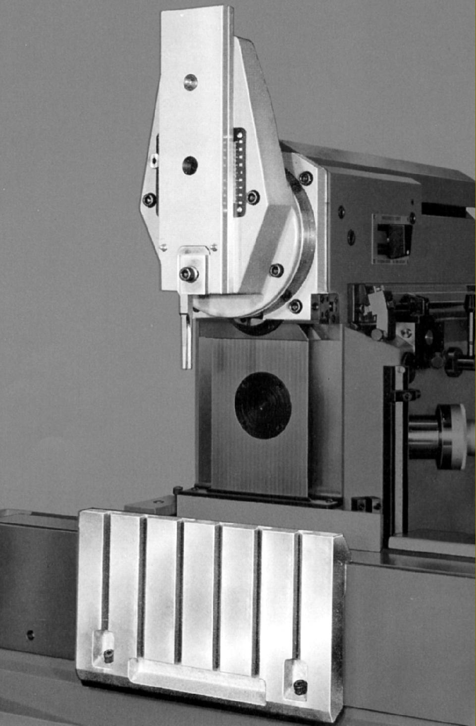
Swing-bracket support to allow a quick change from vertical to horizontal milling
|
|
|
|
|
|
|
|
|
|
|
|
|
|
 |
|
|
|
|
|
|
Early Heidenhain digital read-out display
|
|
|
|
|
|
|
|
 |
|
|
|
|
|
|
Universal Adaptor fitted with the Universal Dividing Head equipped for direct dividing (by an indexing plunger into a gear) and quick workpiece clamping by a lever
|
|
|
|
|
|
|
|
 |
|
|
|
|
Clamped to the vertical saddle is the Universal Inclinable Support carrying the Universal Dividing Head Adaptor fitted with the Circular Clamping Plate
|
|
|
|
|
|
|
|
|
|
|
|
|
|
 |
|
|
|
|
|
|
Universal Dividing Head with standard plate dividing set-up being used in conjunction with the Universal Milling Head attachment.
|
|
|
|
|
|
|
|
 |
|
|
|
|
|
|
Universal Dividing Head equipped for direct dividing (by an indexing plunger into a gear) and quick workpiece clamping by a lever. The plain tailstock shown is also equipped for quick clamping
F5 Page 2
|
|
|
|
|
|
|
|
|
|
|
|
|
|
|
|