|
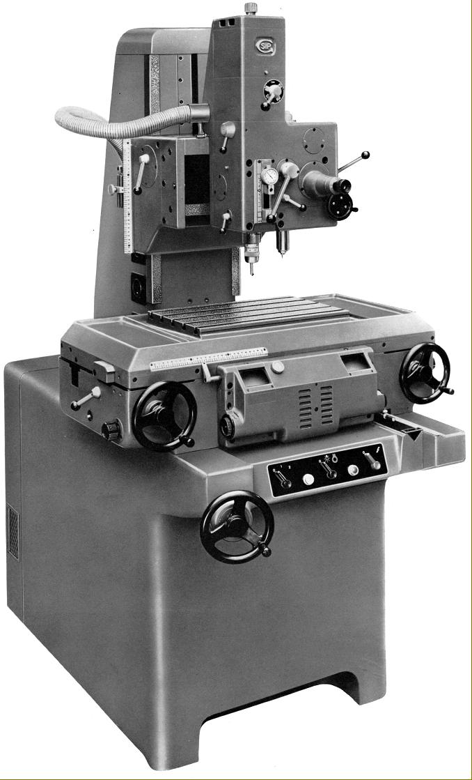
Designed for very small work only - watch and fine instrument work and light milling - the 1-H was one of a pair of smaller ultra-precise SIP jig borers, the other being the slightly larger 2P. With the makers guaranteeing an "accuracy displacement" of 0.00008" (0.002 mm), this was a single-column machine, with a 16" x 10" (400 x 250 mm) table having a working range of 8" (200 mm) longitudinally and 8" (200 mm) across. The table was carried on ways relieved by spring-loaded rollers, thus ensuring both a particularly smooth motion and an accurate, stick-free repetition of settings.
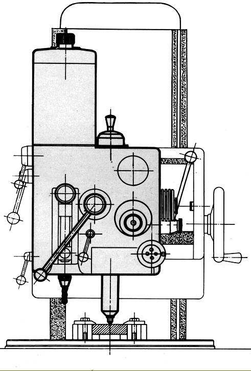
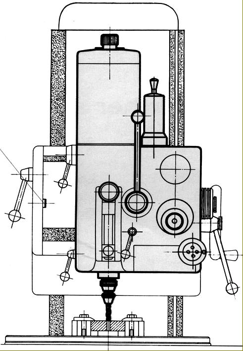
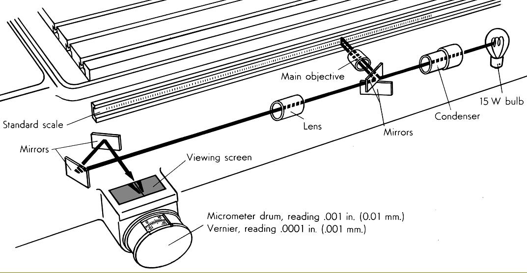
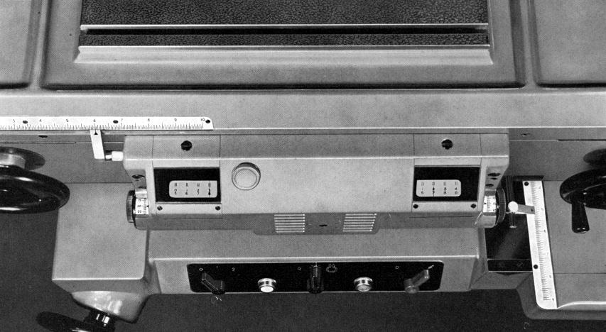
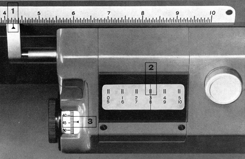
Carried on a machined upright, the head could be locked at the required height on its vertical ways with all spindle feeds designed to be by quill only. The maximum distance between the table surface and the spindle-nose was 12.25" (313 mm) and the throat - the clearance between the inner face of the column and the spindle axis) - was 11.375" (290 mm). Instead of relying on precision feedscrews and giant-sized micrometer drums to indicate table positions, each table slide mounted an enclosed, highly accurate standard scale with the engraved lines illuminated, magnified and projected onto a glare and parallax-free reading screen. The method of taking a reading on this model differed from that on the larger types (where the order was: external scale, micrometer drum, vernier and finally the reticle). First an approximate position for the table (to within 0.05"/1 mm) was established by reference to ordinary external ruler; a position to within hundredths of an inch (0,01 mm) was then read from the reticle (cross hairs) of the projection screens - with the final reading, down to thousandths and ten-thousandths of an inch (0.01 and 0.001 mm) achieved by reference to a micrometer drum and vernier. The viewing screens, carried in a housing on the front of the knee, were visible in normal light and easily read using both eyes, Being an entirely optical system, there was no mechanical strain on the components and no reason why errors should develop, even after years of use.
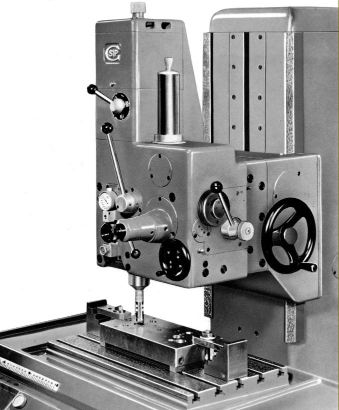
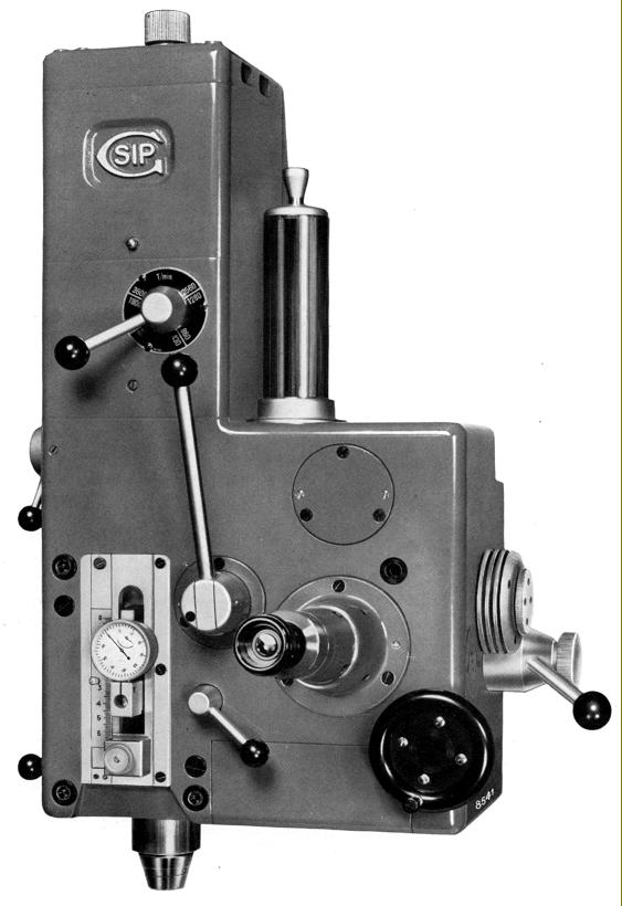
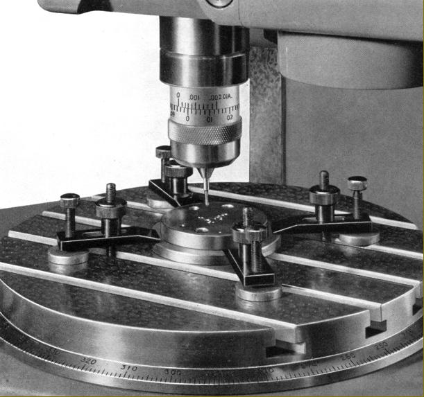
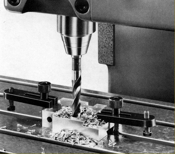
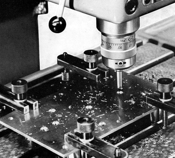
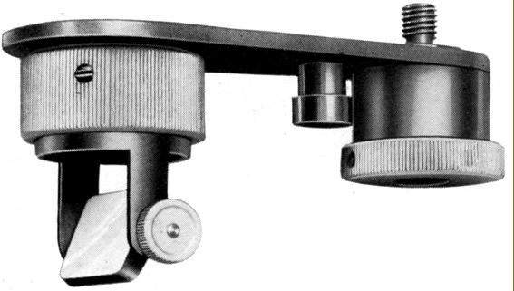
Of patented design, the head incorporated a permanently-mounted, integral microscope and spotting tool (punch) and was able to be moved horizontally on its supporting slide to occupy two pre-set working positions - each aligned with perfect accuracy against solid abutments. In the left-hand position the job was set up (using the microscope to align on previously scribed cross hairs and the spotting tool to mark the centre), and then moved to the right by turning a handwheel though one revolution, where the job was drilled and bored. When the spotting tool was lowered or raised, this was accompanied by an automatic shifting of the microscope, its lower part being automatically retracted and then brought back into the correct position as required. The effect was to allow the spotting tool, viewing microscope and spindle to be each brought (successively) into the same (exact) position by the operation of a single handwheel.
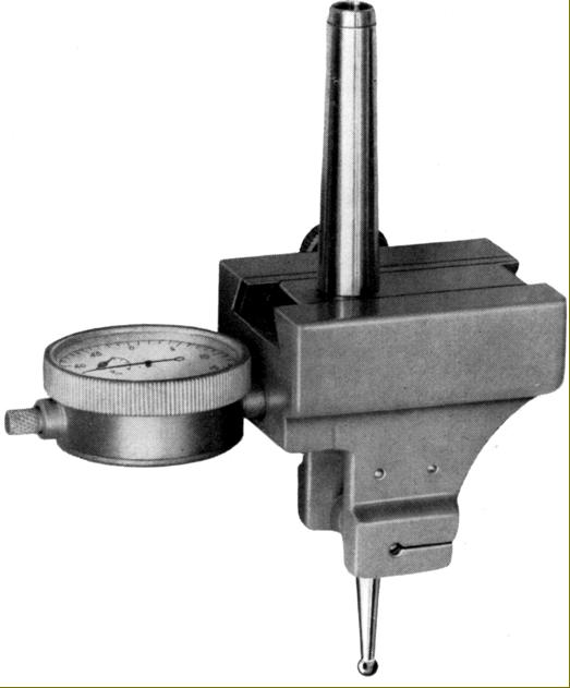
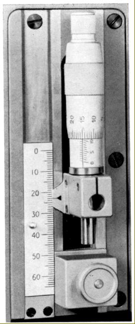
The spindle end was formed with a No. 1 Morse taper on the inside and a special SIP external tool-holding taper in a size 0e (zero-e) - this range extending through 1e, 2e, and 4e to suit increasing sizes of machine and able to hold, with great accuracy, a variety of cutters and boring heads. The 2.125-inch (55 mm) travel spindle ran in special super-precision ball and roller races of SIP manufacture, the rollers and races being "specular ground" to better than 1 micro-inch (0.25µ) by a special process that eliminated the need for further finishing. The bearing rollers had their diameter and concentricity consistent to within 4-millionths of an inch (0.1µ). At the signing-off test, the maximum permitted eccentricity at the spindle nose was 0.00008" (0.002 mm) and the spindle assembly was not allowed to increase in temperature by more than 10°C during a 24-hour run at high speeds. Seven speeds were provided of: 360, 535, 720, 1070, 1500, 2140 and 3000 r.p.m. when fitted with a ¼ h.p. 3-phase, 50 Hz motor - though some 20% faster with a 60 Hz.. The nominal boring capacity was 1" and it was recommended that drilling be limited to 9/16" (15 mm) in cast iron and ½" (12 mm) in soft steel. A built-in ruler scale, dial-indicator and gauge block mounting allowed down-feed positions to be determined to within 0.0005" (0.01 mm) over the whole travel range.
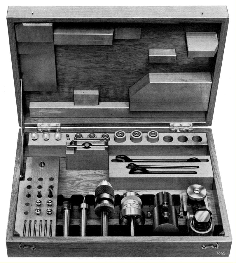
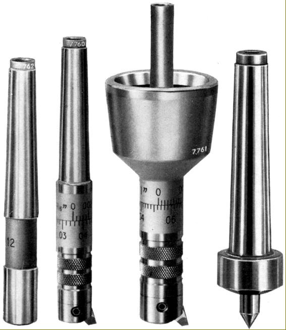
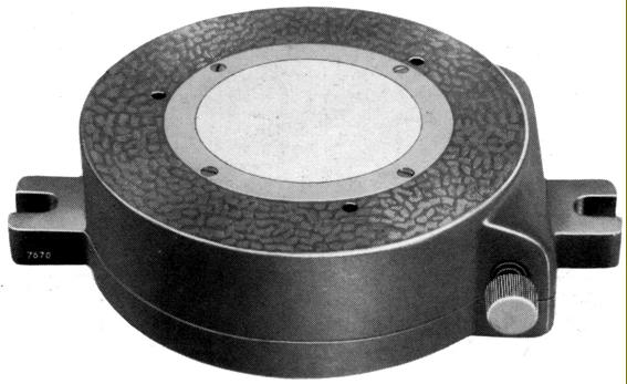
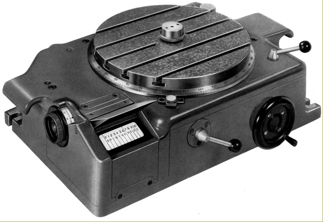
Bearing in mind its small size and special application, accessories were limited to specially-made units: a range of high-precision drills, cutters, cutter holders and micro-adjustable boring heads and the 8.625" (220 mm) SIP Rotoptic-1 Optical Circular Dividing Table. This, the smallest of this Rotoptic range, had readings shown on a viewing screen projected from a built-in circular ruler made to standard scale accuracy with angular settings down to 1 second of arc possible.
With an overall front-to-back measurement of 50" (1264 mm), a width of around 30.4" (900 mm) the No. 1H weighed approximately 1900 lbs (850 kg) net - or more than twice as much as, for example, other small jig borers such as the Linley and Downham...
|
|