|
Machine Tool Manuals Machine Tool Catalogues Accessories Belts Wade Home Page Wade 8A Toolmakers' Lathe Wade "Front-way" Lathe The Last Wade Other Wade Products |
||
|
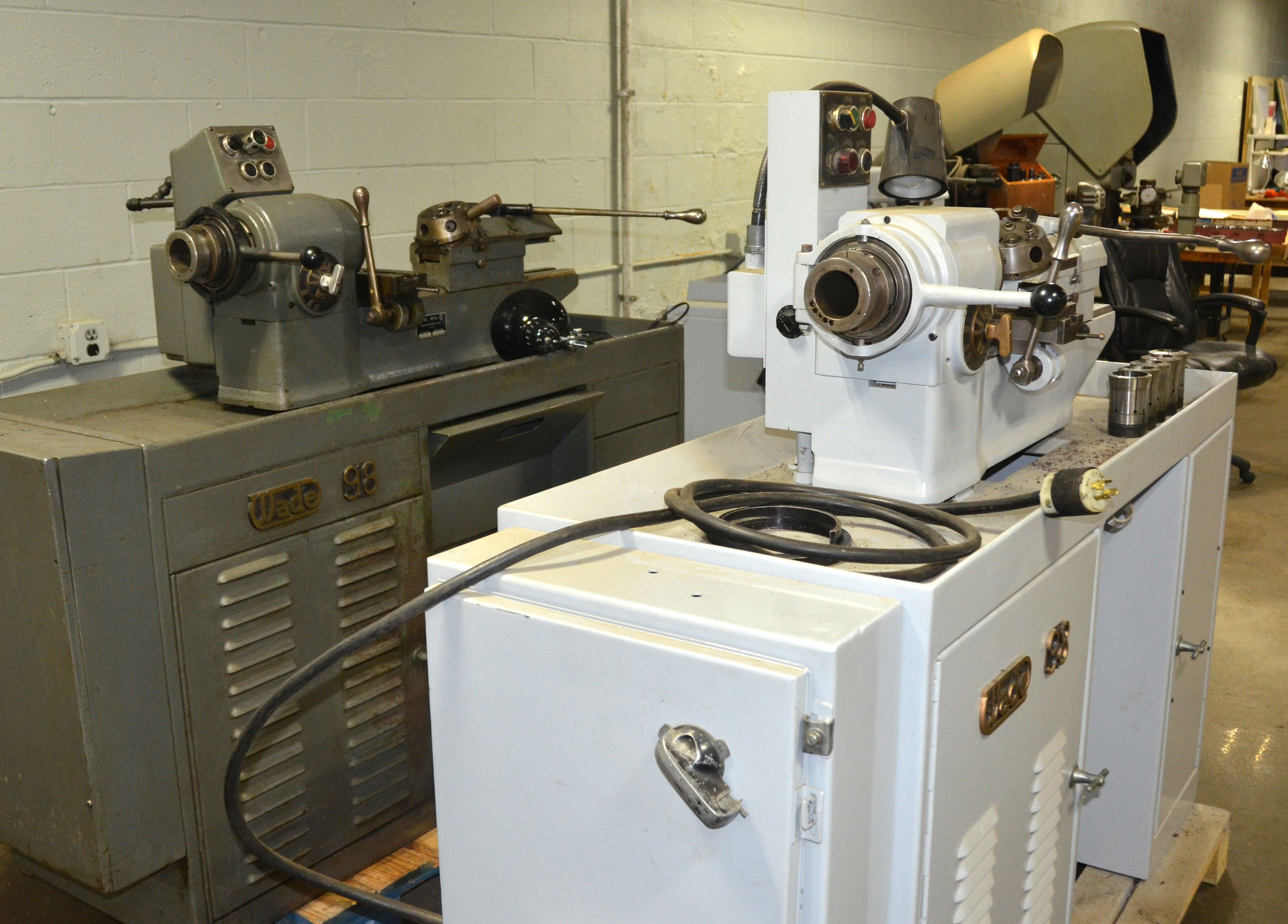
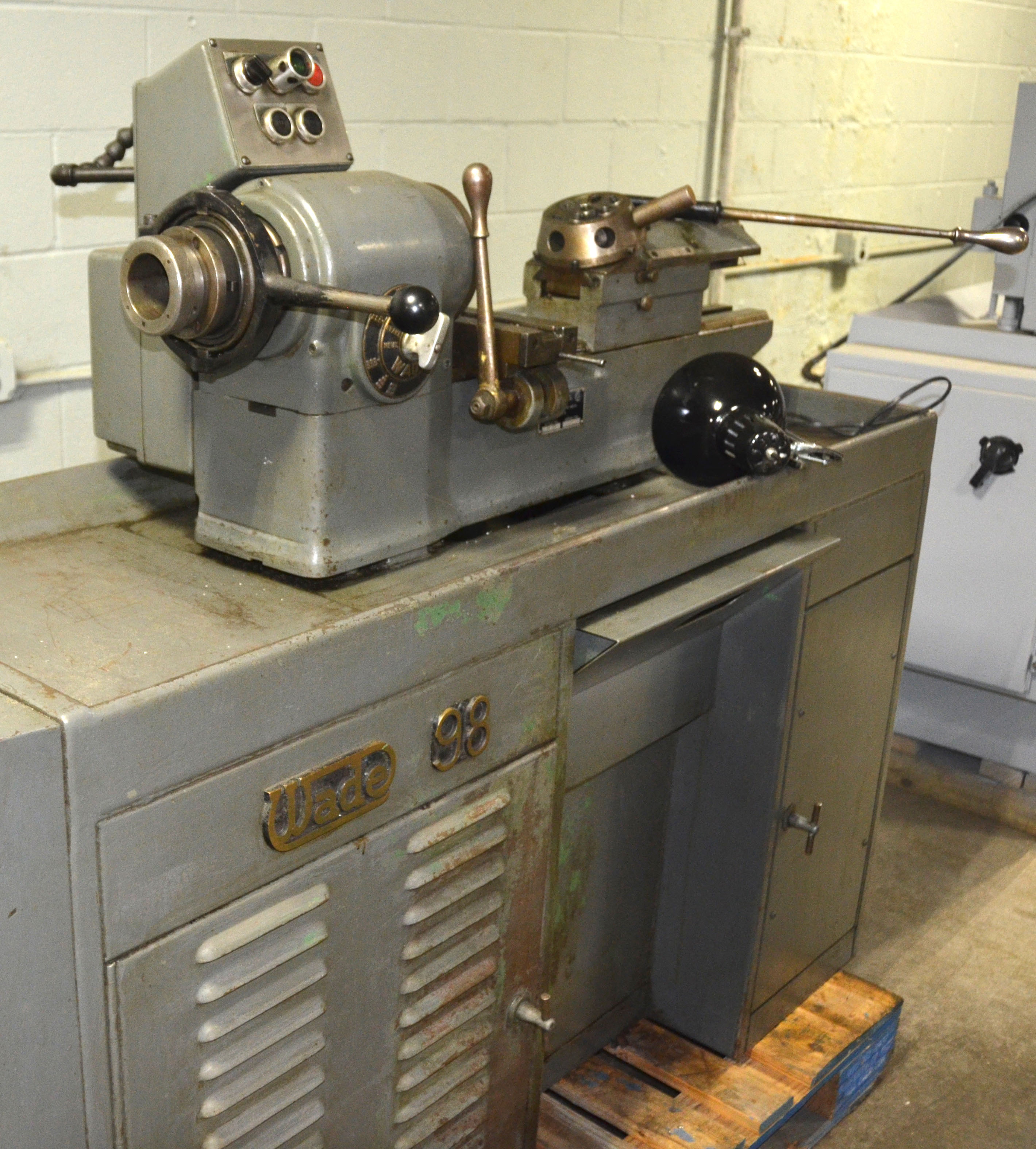
Continuing the Company's tradition of manufacturing fine-quality small lathes, the Ward Production plain-turning lathe was given the Model designation. 94/98 EC. It was built in two versions: the more common early type distinguished by a rounded top to the headstock and a much rarer late version with a flat-topped headstock. |
|
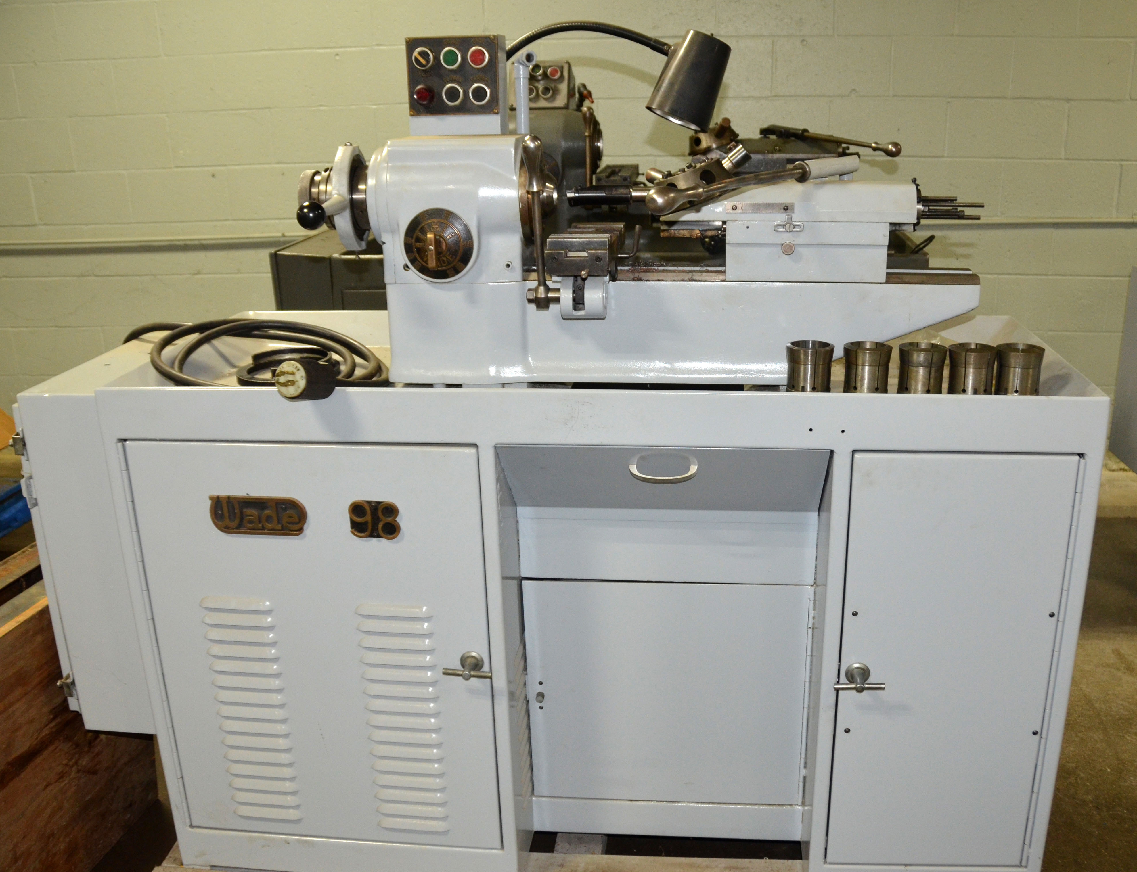
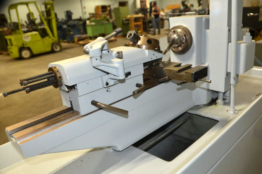
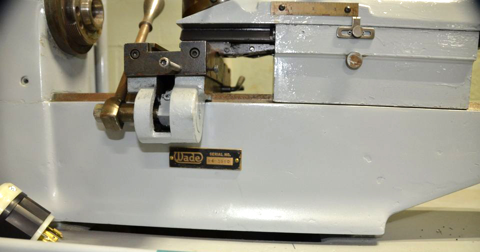
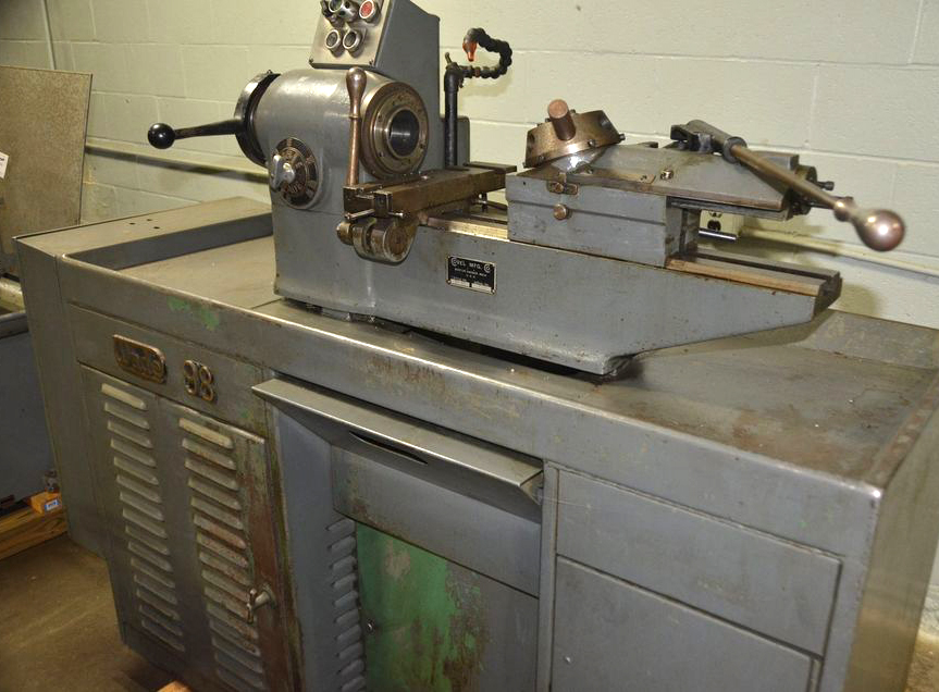
Wade lathe No. 94 E.C fitted as a precision plain-turning lathe with a very robust compound slide rest and a conventional tailstock. |
||
|
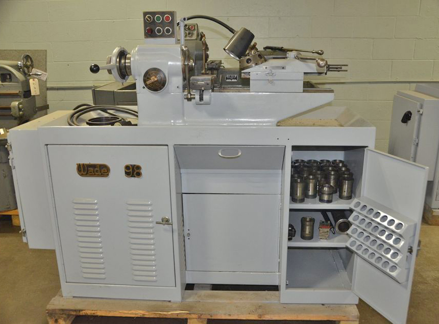
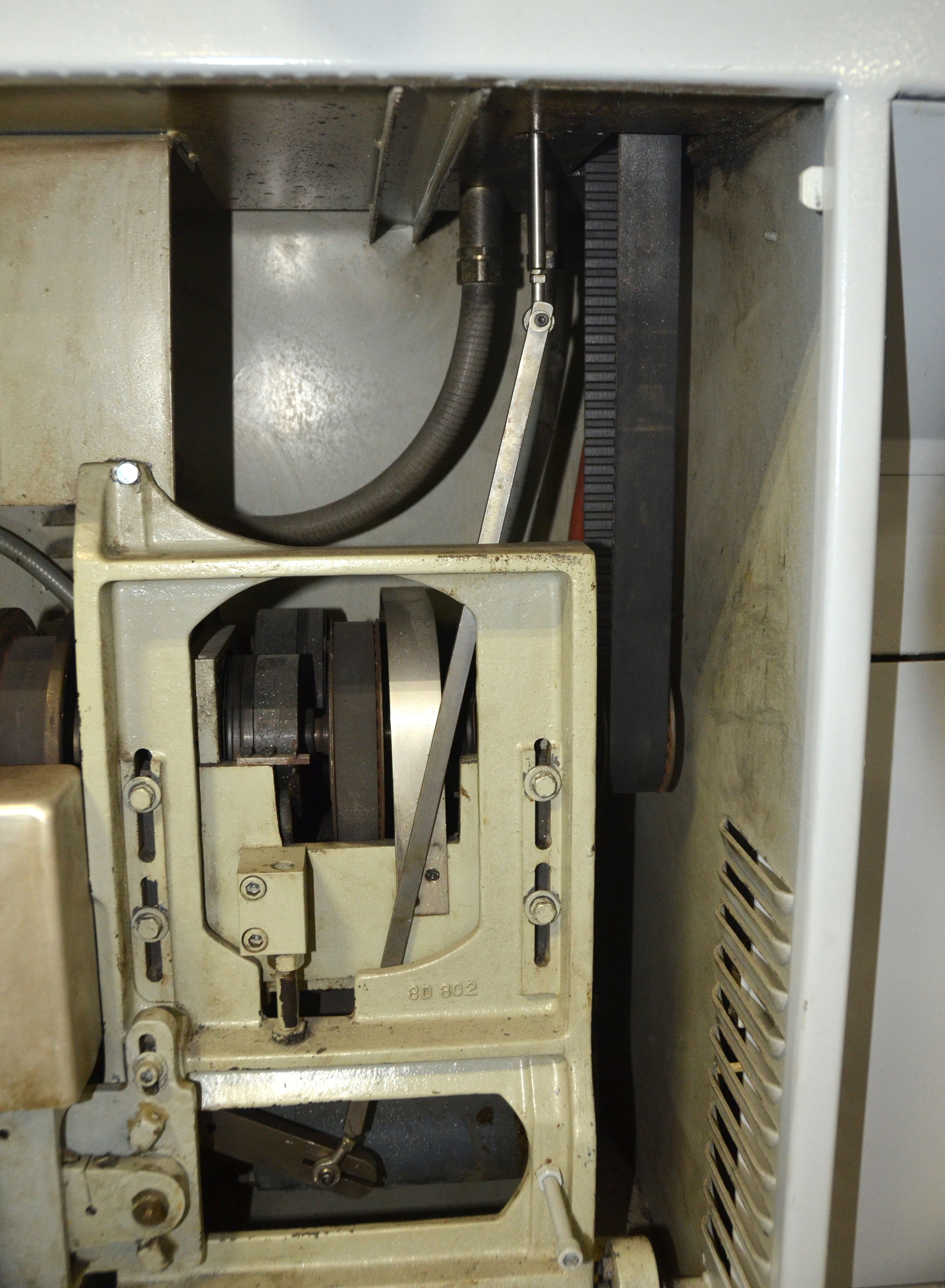
Wade No. 94 stand showing the substantial variable-speed drive unit in the left-hand compartment, coolant pump in the centre on a hinge-out door and a collet storage rack (made of aluminium) mounted on the inside face of the right-hand door. |
||
|
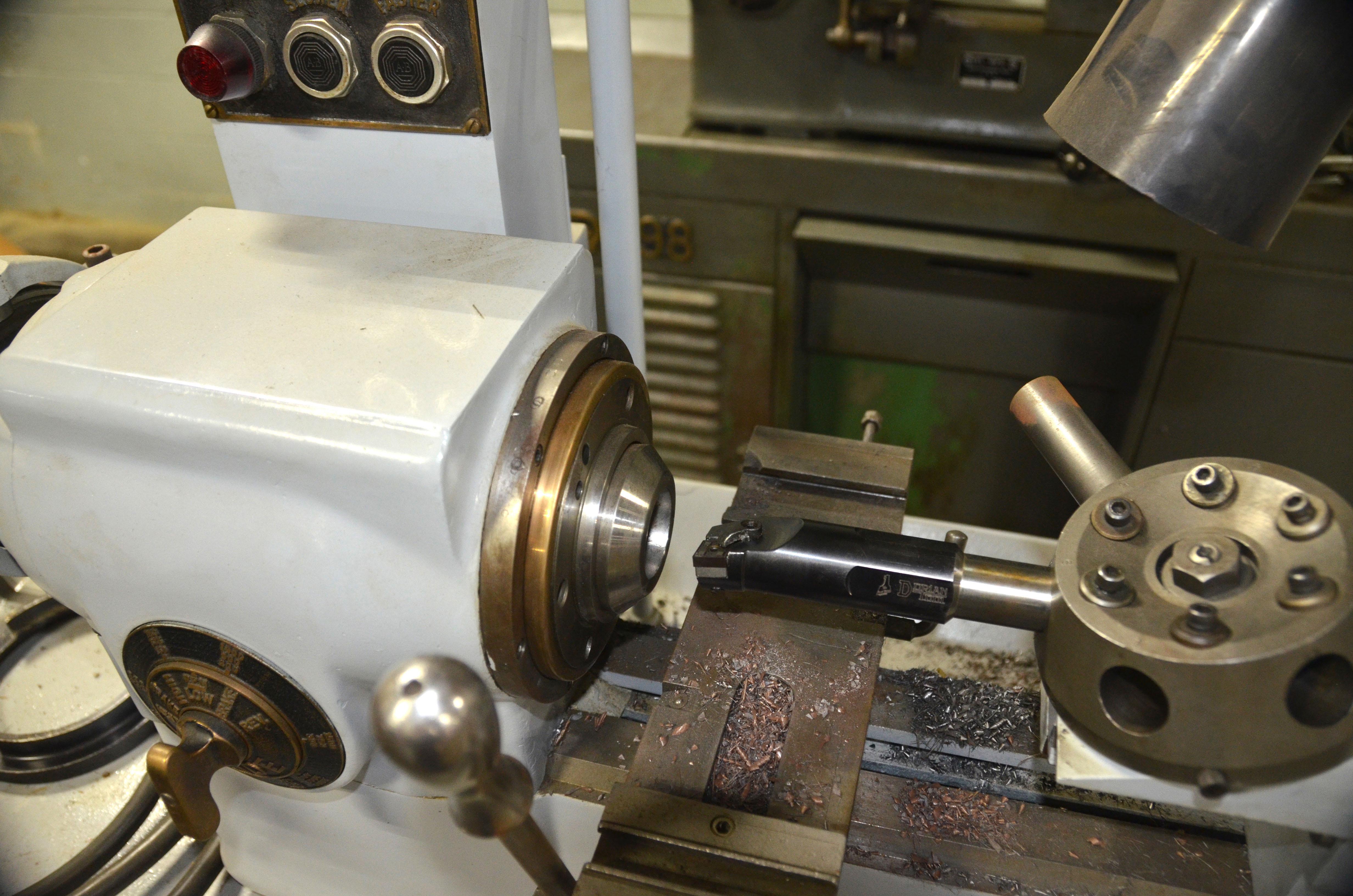
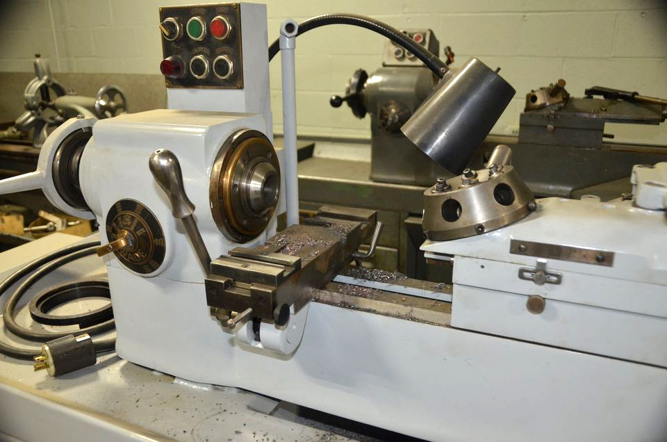
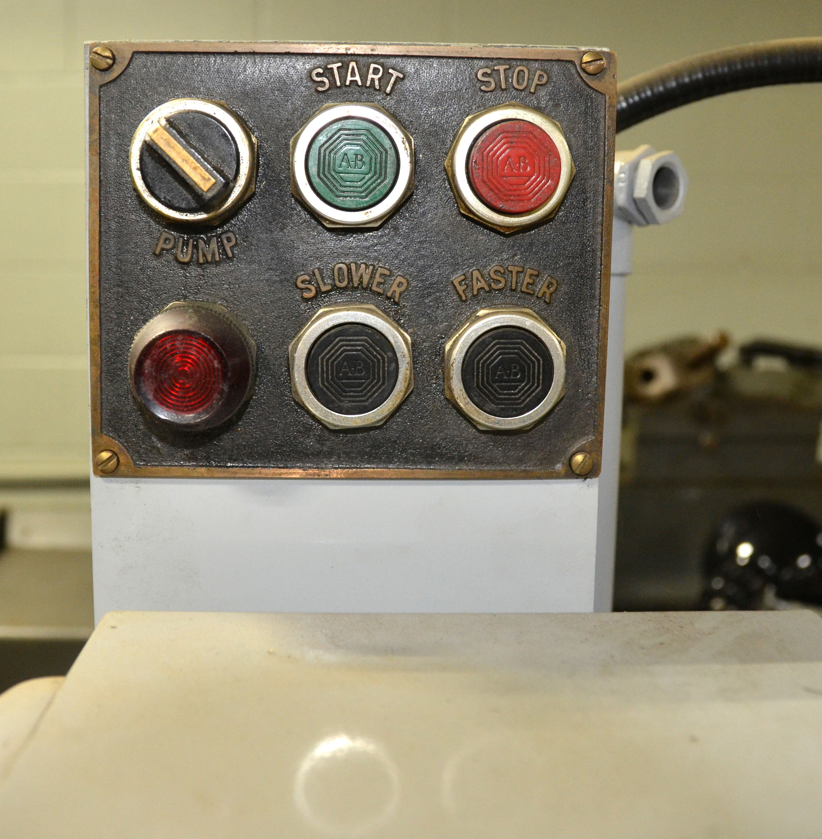
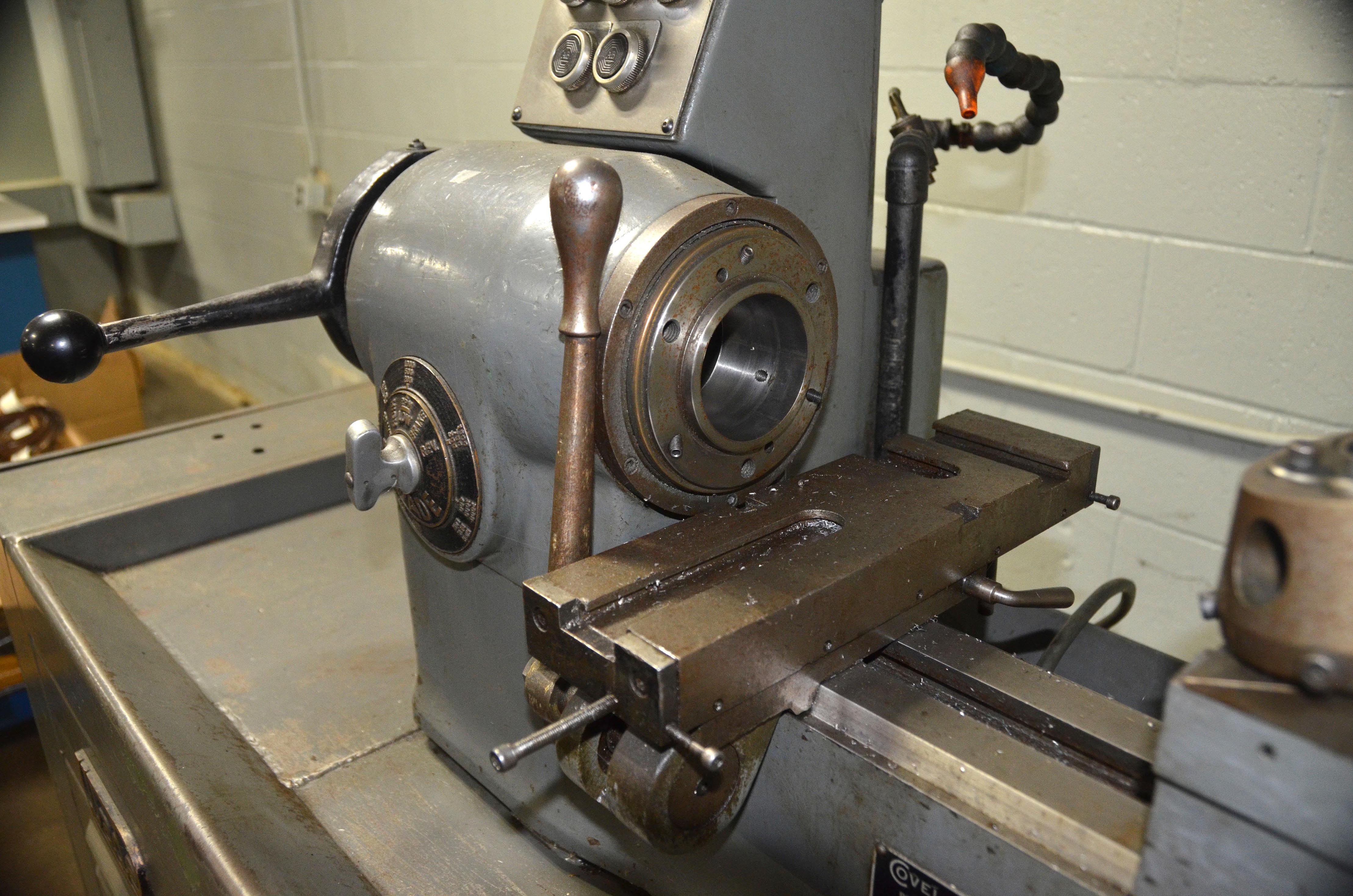
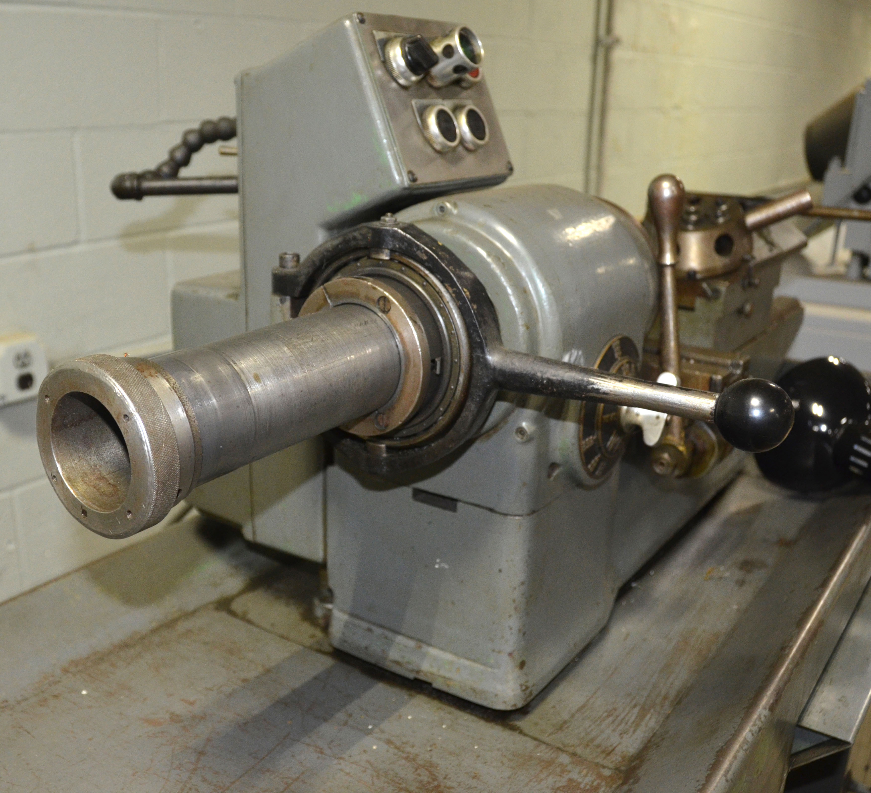
Headstock detail showing the two push buttons by which the spindle speed could be increased or decreased and the face-mounted control handle for operating the electrical clutches which could selected both the high and low speed ranges, and reverse, without stopping the motor. Later lathes had a headstock consul with six push buttons. |
||
|
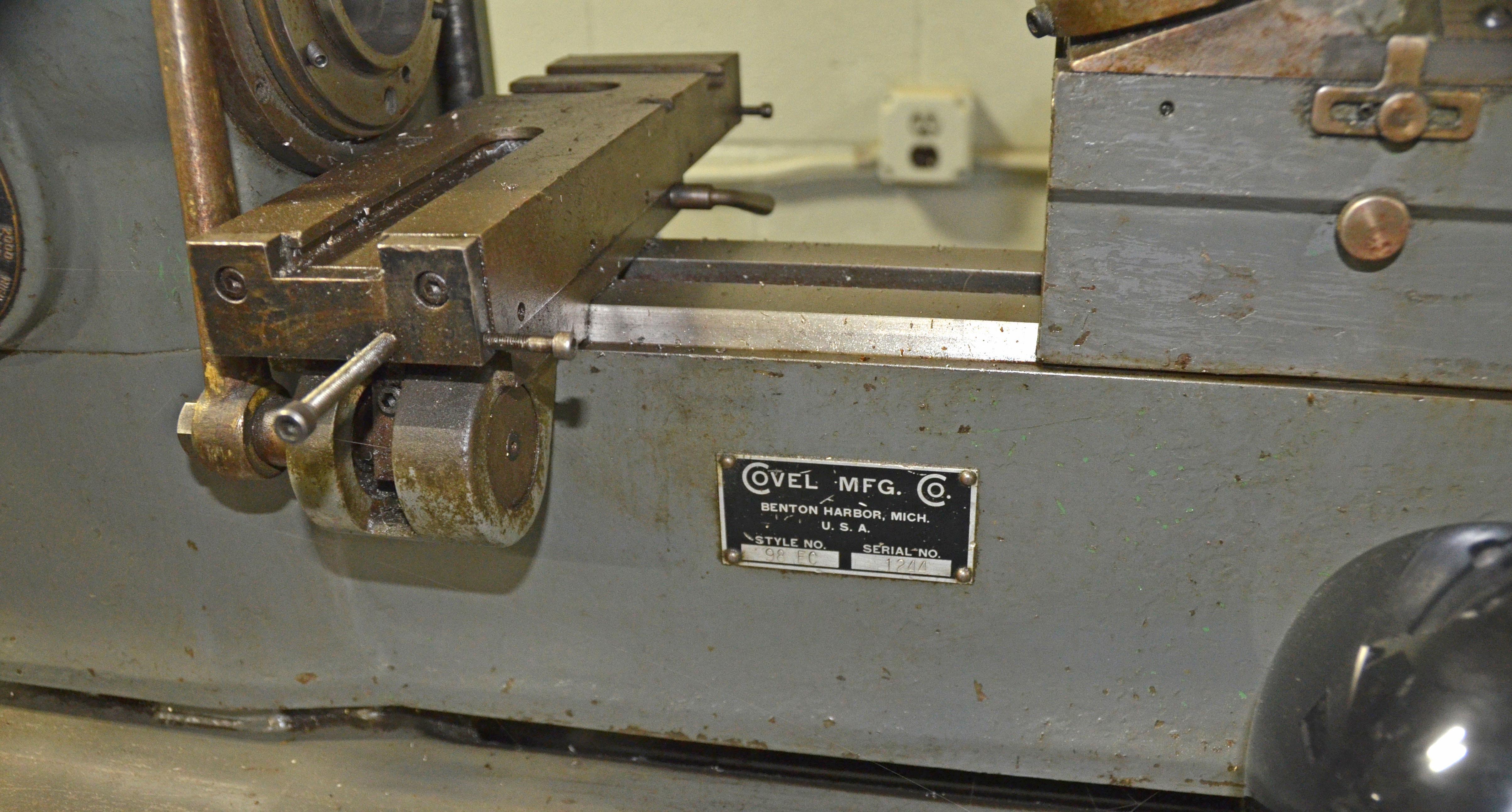
Wade described the No. 94 Compound Slide as their "Super Slide Rest". Unlike the same type unit fitted to their Precision Bench Lathe and No. 8A Screwcutting lathes, the cross slide base was fully covered and the micrometer dials - at last on a precision bench lathe of any make - pleasingly large. |
||
|
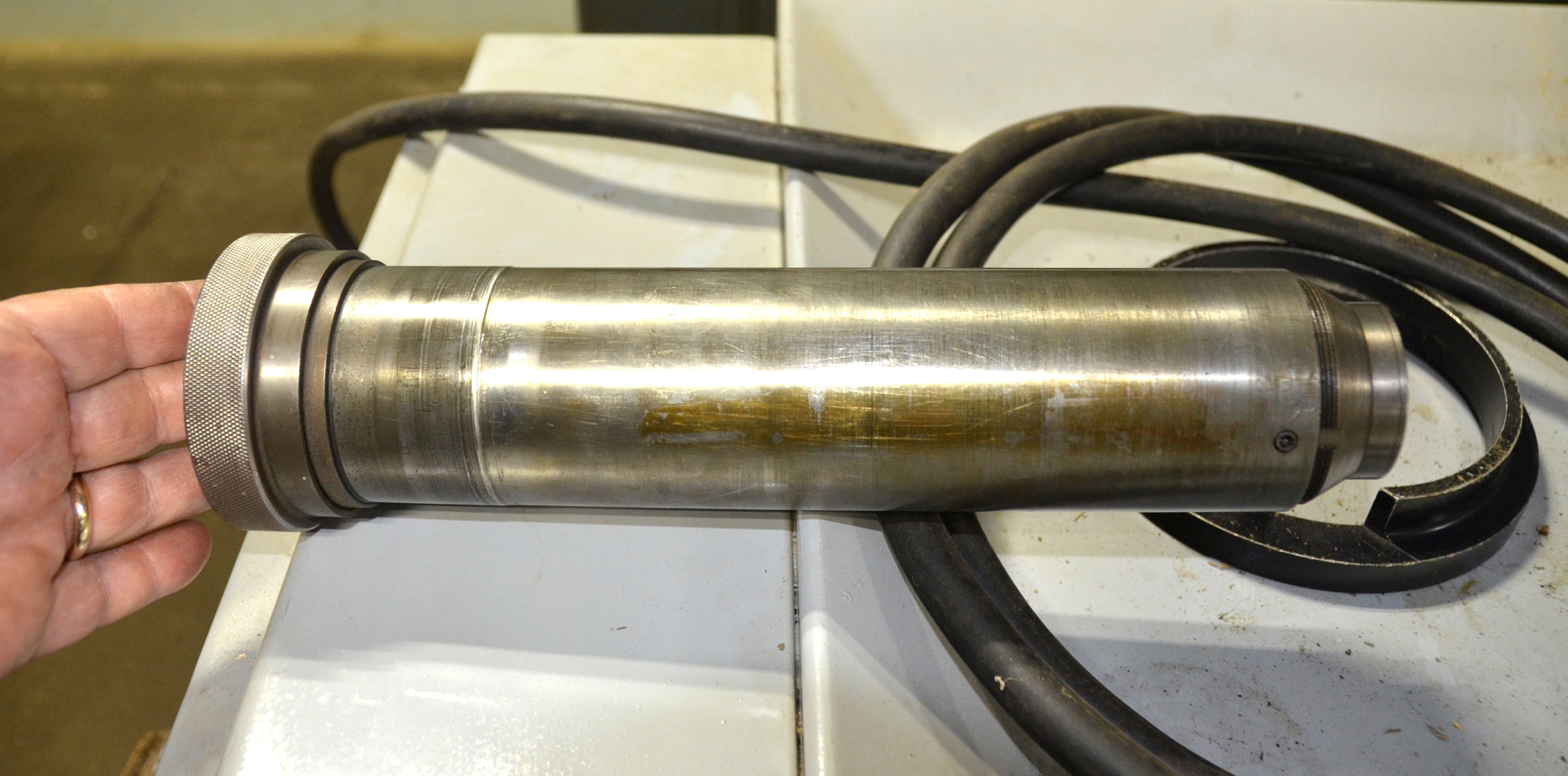
The Wade 94 Headstock Spindle ran in precision, anti-friction, heavy-duty, double-row, cylindrical roller SKF bearings set under a light preload. |
|
|
|
|
|
|
|
|
|
|
|
|
|
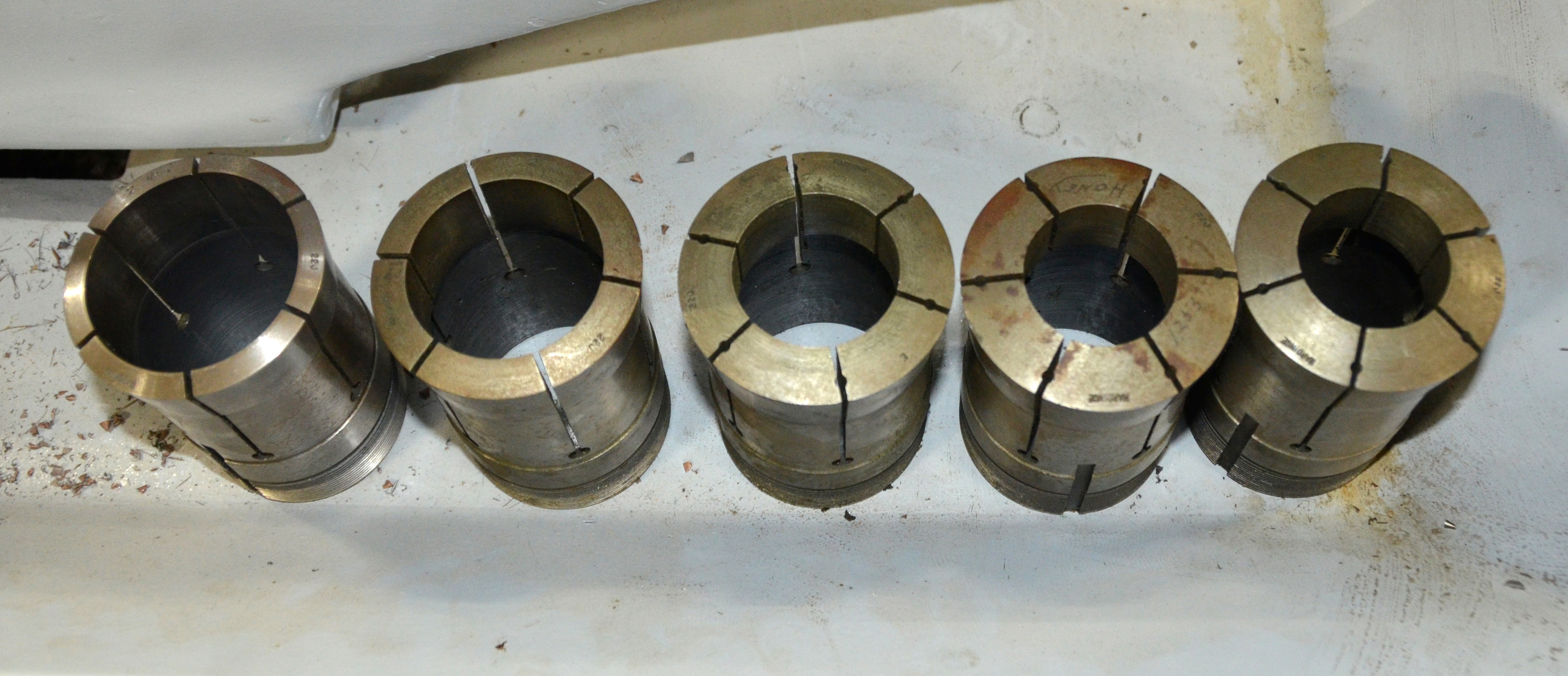
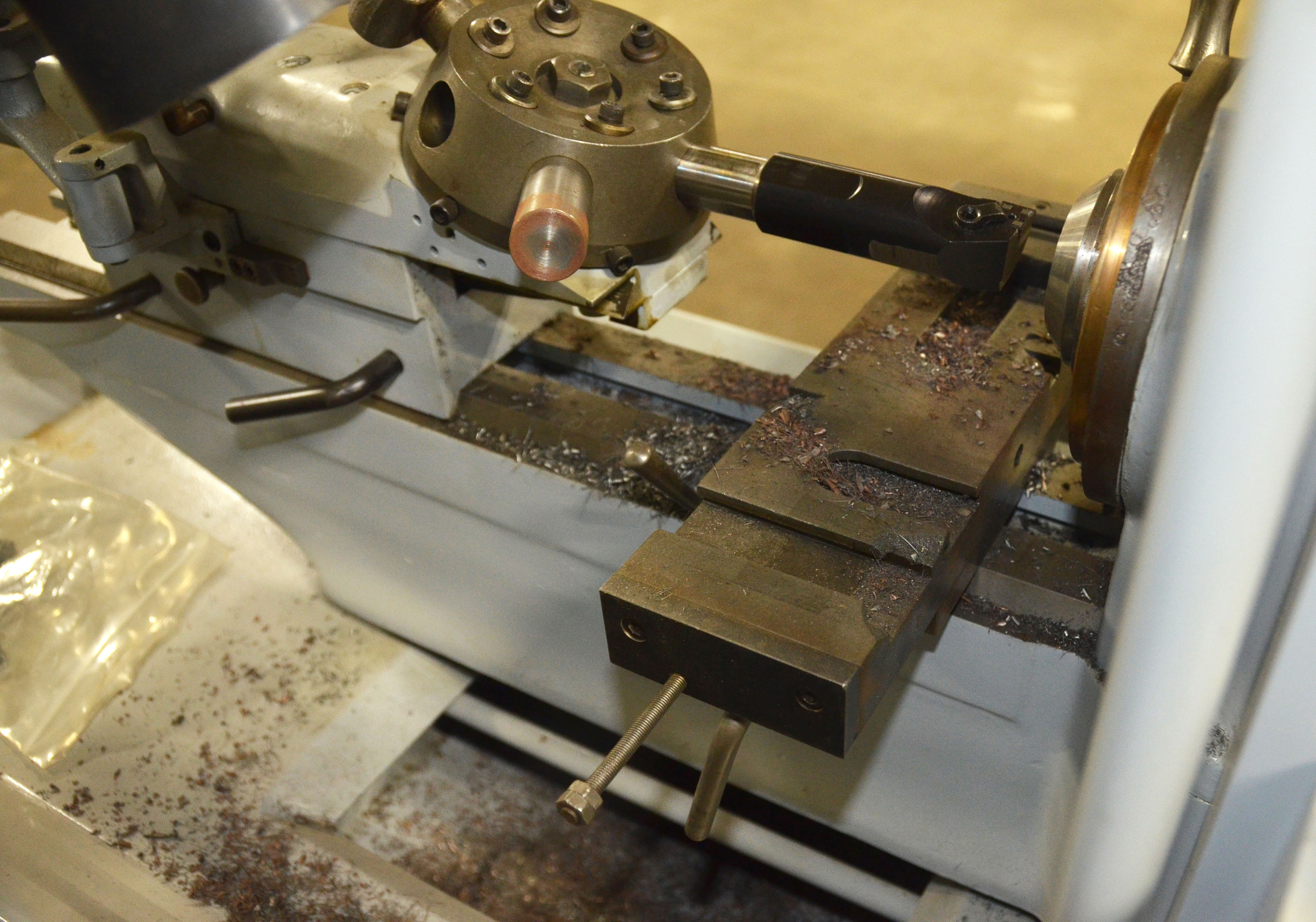
Another method on controlling precise shoulder length when using collets was provided by the simple Wade "Collet Stop" assembly. A long rod, held immovable in the spindle by an fastening incorporated within the draw bar tube, protruded into the collet and carried on its end a replaceable "pad". The pads were supplied in two diameters of solid material, and another incorporating a spring for quick work ejection. Different pads could easily be made and fitted by the user. |
||
|
Material is held in an ordinary collet is moved backwards slightly when the collet tightens on it - the Wade Stator Collet" was designed to overcome this limitation to precise shoulder-length setting by holding the work stationary. |

|
Wade "Front-way" Lathe The Last Wade Machine Tool Manuals Machine Tool Catalogues Accessories Belts |
||