email: tony@lathes.co.uk
Home   Machine Tool Archive   Machine-tools Sale & Wanted
Machine Tool Manuals   Catalogues   Belts   Books  Accessories

Wade "Bench Profiling Machine"

Wade Home Page   Wade Profiler Photographs

Manufactured during WW2 by the Wade Tool Company of 53 River Street, Waltham, Mass., their bench profiling machine was intended for the machining of irregular shapes and contours, slotting, recessing, routing and light vertical milling. Two versions were offered, one with a countershaft drive the other the spindle driven by a flat belt from a motor (possibly a variable-speed type|) bolted vertically to the back of the machine. On the latter version, in order to allow vertical movement of the spindle, the pulley on the motor was made long enough so that the belt could slide up and down.
As the maker was a long-established producer of high-class machine tools, including precision bench and screwcutting lathes and specialised equipment for the watch and clock industries, the profiler was of the highest quality, built by experienced craftsmen from top quality materials and intended for heavy use under production conditions.
Falling into the same sub-miniature class as, for example, the Derbyshire Micromill, Pricise and Childs machines, the Wade was of essentially simple construction and tiny proportions. It was mounted on an oil-pan base of cast iron and had overall dimensions of 19" wide, 24" deep and 22" high. Two uprights, bolted to the left and right-hand faces of the base, were joined at the top by a casting formed with V-edged ways along its top and bottom faces on which ran, from side to side, a second casting machined with vertical ways to hold a spindle and side-mounted tracer-pin assembly. Control of the head's movements - side to side of 2" and vertically of 1.5" - was by a most unusual system and one obviously intended for production work: a single lever working through a ball-and-socket joint. With vertical and side-to-side travel on the head, the table needed only to be moved front to back, travel being under the control of a long lever, pivoting from the left-hand side of the base, and able to be adjusted as to both stroke length (the maximum was 4.5") and rate of feed from rapid to sensitive, as required. Each axis of travel was provided with screw-adjustable stops equipped with round, knurled-edge locking nuts.
Continued below:

Continued:
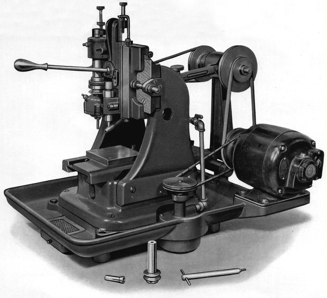
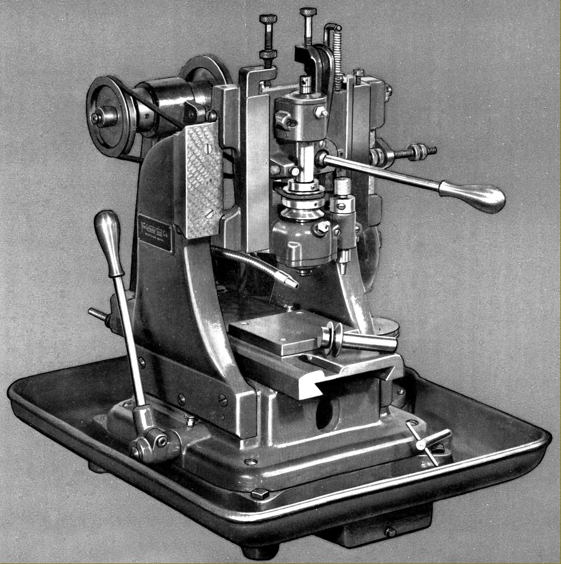
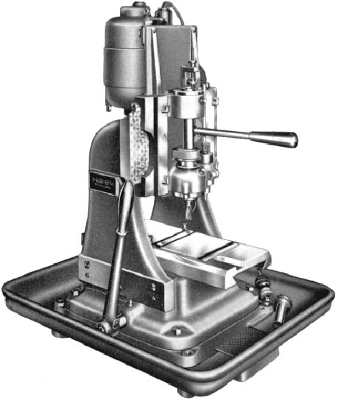
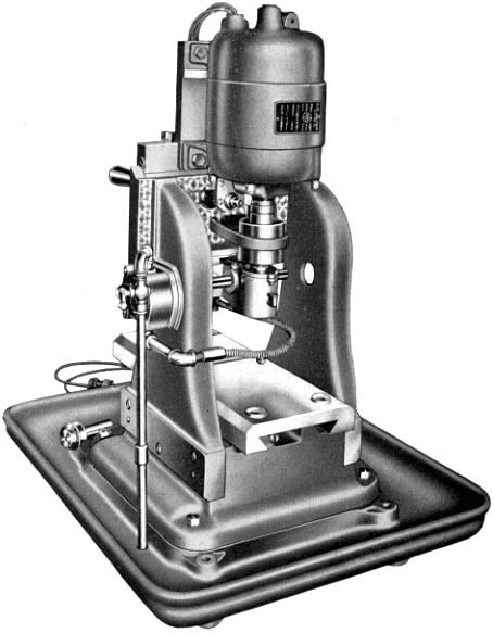
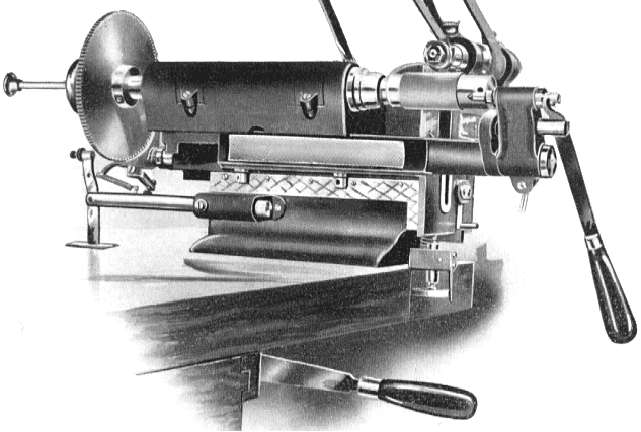
Work-holding facilities could hardly be described as convenient, with just a plain-topped, 4" x 4" x 1/2" steel block screwed to the horizontal slide - the intention being that the toolroom would  make up a number blocks, as required, with jigs or fixtures arranged on them for production - the actual machining being carried out by
women or unskilled help. In addition to the workpiece, when profiling or copying was to be undertaken, a hardened template (or some other form of guide) was positioned next to the job so that a tracer pin could engage with it. It was also possible for a skilled machinist to use the machine to cut its own masters or templates, the standard equipment including a cutter spindle and tapered end mill to fit in place of the ordinary follower - with a follower pin made to the same diameter as the cutter that would be later be used on the work, held in the regular spindle. Thus, when the master was cut, it was already clamped in position, ready to be used as a template and the job could then be handed over to the unskilled operator. It would also have been possible to replace the block with a custom-made example, perhaps having T-slots or lines of drilled and tapped holes for gripping one-off or short-run jobs. When set up for work, the cutter spindle could cover a maximum area of 2" by 4" with cutters held by draw-in collets with a maximum capacity of 5/16".
Power came from a 1/4" h.p. 1700 r.p.m. 3-phase motor, mounted on plate formed at the back right-hand corner of the base, with initial drive by a 2-step V-pulley to a hinged-base countershaft that gave four speeds spanning 2000 to 4000 r.p.m. A central bearing assembly, using sealed ball races carried in an eccentric housing to allow adjustment of the motor belt tension, was fitted with a through shaft that had the pulleys overhung, one to the left the other to the right. To tension the final drive belt the countershaft was pushed backwards and a thumb screw tightened against a bar connected to the machine and passing into a tube fastened to the countershaft. To allow the spindle to move freely up and down, the final drive belt was normally a round, woven endless type of impregnated cotton, twisted through a quarter of a turn so that it could run round one of two pulleys positioned between the spindle's pre-loaded, ball-race bearings. However, if work involved using lower speeds on steel, a V-belt could be substituted, the change from one to the other eased by the removal of two cap-head screws that allowed the upper bearing assembly to be rotated half a turn to expose a gap though which the belt could be threaded.  A second drive from the motor, using a twisted rawhide belt, was used to power a built-in coolant pump, the liquid being directed through steel pipes to a flexible nozzle head.
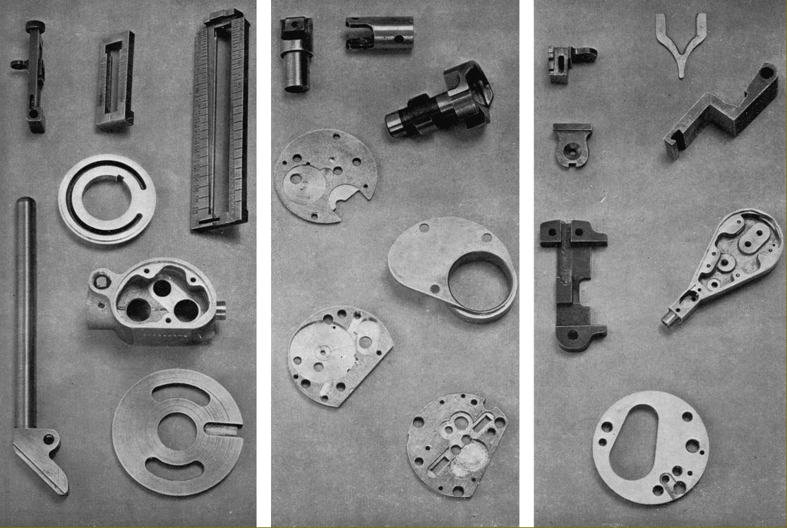
In use, the operator gripped the head lever in the right hand and the table lever in the left; the cutter was brought down to the work and, by means of the two levers guided the tracer pin around the template or master guide. The procedure obviously required some practice to master but, once well practiced, the makers claimed that the action was quick and certain and tiny jobs -
mechanical time fuses, time bomb fuses, bomb parts, breech mechanisms, range-finder parts, gun sights, typewriter and adding machine plates and levers, etc. - could be turned out to very high standards of accuracy.
As was the case with many specialised machines, the maker's offered a service to customers inviting them to send work samples or drawings so that advice could be offered on the best way to proceed.
Although it is believed that several hundred examples were made, few if any can have survived. If any reader has a Wade bench profiling machine the writer would be interested to hear from you.  Photographs of a Wade bench profiler
can be seen here

Another version of the Wade bench profiling machine with the spindle driven by a flat belt from a motor (possibly a variable-speed type|) bolted vertically to the back of the machine. In order to allow vertical movement of the spindle, the pulley on the motor was made long enough so that the belt could slide up and down.

The Wade Bench Profiling Machine with vertical motor - rear view.

Examples of work produced - or finished - on the Wade bench profile machine

Wade Automatic Pinion Cutter.
This type of machine was made by many precision lathe makers as an adjunct to their work with watch and clock factories. It was used to produce accurately cut "wheels" (gears) for use in scientific instruments and meters, electrical control apparatus and other mechanically controlled items which often relied, in the days before electronics, upon a myriad of interlocking, pivoted, articulated and geared mechanical assemblies. A good example of this type of construction would be the mechanical "torpedo-run" computer carried on submarines. If you ever have the chance to acquire one (most were sold off many years ago, and cannibalised) buy it - and marvel at the no-limit-on-cost precision miniature engineering it contains.
The Wade machine had its Cutter Spindle was mounted on dovetail slides, which allowed both a horizontal and vertical movement, whilst delicately-adjustable stop screws controlled the depth and location of the cut.
The Work Arbour Spindle was mounted in a slide, which moved horizontally at right angles to both cutter movements. Attached to the Work Slide was an Arbour Support - which is shown moved to one side in the illustration above.
The cycle of operation was as follows: the work fed past the cutter, the cutter lifted out of position, the index mechanism operated and the work slide returned for the next cut. The index mechanism was a friction type, with a positive lock and automatically stopped the machine after one revolution of the work.
Once set and running the device required little attention, and it was possible for an operator to attend to several machines; the machine was started by raising the lever. Shown protruding from the front face of the bench.
The gear blanks (which could be a maximum of 3-inches in diameter) were slipped from a previously-loaded charger onto the work arbour, which located them by the inner diameter of their rims. The stack of blanks, which could be up to 2
1/4-inches long, was held tightly against the arbour shoulder by a nut whilst a centre could also swung into position to provide extra support.
A cutter of 1
1/4" diameter was recommended (although a non-standard one could be used) and the work spindle accepted the Wade No. 3 standard chuck.
The machine was supplied with one index plate and one cutter arbour; it occupied a bench space of 20" x 24" and was 10" high. Its weight, with a countershaft assembly, was 110 lbs..

Wade Home Page   Wade Profiler Photographs

E-Mail Tony@lathes.co.uk 
Home    Machine Tool Archive    Machine Tools For Sale & Wanted
Machine Tool Manuals   Machine Tool Catalogues  Accessories  Belts


Wade "Bench Profiling Machine"